1
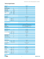
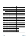
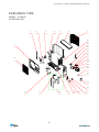
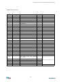
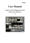
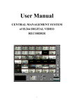
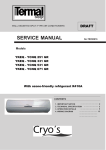
SERVICE MANUAL
Inverter T-series Split System Air Conditioner
• T70-R410i 7.5kW Split System Inverter
www.ayre.com.au
Service Manual • Inverter T-series Split System Air Conditioner
Contents
1. Important notice................................................................ 2
2. Technical specifications................................................... 3
3. Operation details................................................................ 4
4. Wiring diagram.................................................................11
5. Explosion view – indoor unit.......................................12
6. Explosion view – outdoor unit....................................14
Service Manual • Inverter T-series Split System Air Conditioner
Important notice
This service manual is intended for use by individuals possessing adequate
backgrounds of electrical, electronic and mechanical experience. Any attempt
to repair the appliance may result in personal injury and property damage.
The manufacturer or seller cannot be responsible for the interpretation of this
information, nor can it assume any liability in connection with its use.
The information, specifications and parameter are subject to change due to
technical modification or improvement without any prior notice. The accurate
specifications are presented on the nameplate label.
How to order spare parts
To have your order filled promptly and correctly, please furnish the following
information:
1. Model number with indoor or outdoor
2. Number in the explosion view
3. Part name
4. The quantity you require
2
Service Manual • Inverter T-series Split System Air Conditioner
Technical specifications
Model No.
T70-R410i
Compressor
Inverter
Control type
Remote
Rated cooling capacity
W
7,000
Rated heating capacity
W
7,500
EER for cooling
W/W
3.00
COP for heating
W/W
3.10
Moisture removal
Litres/h
2.5
High
dB(A)
47
Med.
dB(A)
45
Low
dB(A)
42
dB(A)
74
Indoor noise level at
cooling
Outdoor sound power level
Electrical Data
Power supply
220-240V~50Hz
Voltage range
Rated current
Rated input
V
155~265
Cooling
A
10.0
Heating
A
10.2
Cooling
W
2,300
Heating
W
2,340
Refrigerating system
Refrigerant
R410A
Evaporator
Louver fin and grooved tube type (φ7)
Condenser
Corrugated fin and grooved tube type (φ9.52)
Expansion device
Capillary tube
Defrosting system
Microcomputer controlled reverse system
Fan System
m3/h
Indoor air circulation (H)
1100/1100
Indoor fan type
Indoor fan speed H/M/L
Cross Flow
Cooling
rpm
1400/1240/990
Heating
rpm
1400/1240/990
Dry
rpm
990
Sleep
rpm
990
Indoor fan motor output
W
35
Outdoor fan type
Propeller fan
Outdoor fan speed
rpm
860
Outdoor fan motor output
W
160
Connections
Flare type
Refrigerant coupling
Connecting pipe
Connecting wiring
Gas
Inches
Liquid
Inches
5/8''
3/8''
Size x Core number
4x0.75, 2x0.75, 2x0.2
O.D 16mm
Drainage pipe
Others
Suitable area
m2
30-50
Net dimensions
Indoor
mm
1033×313×202
(W x H x D)
Outdoor
mm
900×805×360
Indoor
kg
Outdoor
kg
Indoor
mm
1103×400×300
1031×835×447
Net weight
Packing dimensions
(W x H x D)
Gross weight
14
56
Outdoor
mm
Indoor
kg
17
Outdoor
kg
62
2
Service Manual • Inverter T-series Split System Air Conditioner
Operation Details
Remote controller
Remote controller
The remote controller transmits signals to the system.
1 ON/OFF button
Used to start and stop operation
when pressed.
2
SLEEP TIMER ON TMIER OFF
FEEL
COOL
DRY
FAN
HEAT
AUTO
HIGH
MID
LOW
SWING
3
3
5
SLEEP
FAN
7
2
TIMER
SWING
6
ON/OFF
1
8
MODE
TIMER button
Used to select TIMER operation.
UP button (TOO COOL button)
Used to increase the set room temperature
and time.
4
DOWN button (TOO WARM button)
Used to decrease the set room temperature
and time.
5
SLEEP button
Used to set or cancel sleep mode operation.
4
6
VANE control button
Used to adjust airflow direction.
7
FAN SPEED control button
Used to select the indoor fan motor speed:
Auto, High, Mid and Low.
8
MODE button
Used to select the type of operation mode: Feel,
Cooling, Dry, Fan and Heating(Only for Heat Pump).
Note: Each mode and relevant function will be further specified in following pages.
Remote Control
The remote controller is not presetted as Cooling Only Air Conditioner or Heat Pump by manufacturer.
Each time after the remote controller replace batteries or is energized, the arrowhead will flashes on the front of
Heat or Cool on LCD of the remote controller.
User can preset the remote controller type depending on the air conditioner type you have purchased as
follows:
Press any button when the arrowhead flashes on the front of Cool , Cooling Only is set.
Press any button when the arrowhead flashes on the front of
Heat , Heat Pump is set.
If you don t press any button within 10 seconds, the remote controller is preset as Heat Pump automatically.
Note :
If the air conditioner you purchased is a Cooling Only one, but you preset the remote controller as Heat Pump, it
doesn t bring any matter. But if the air conditioner you purchased is a Heat Pump one, and you preset the
remote controller as Cooling Only, then you CAN NOT preset the Heating operation with the remote controller.
4
Service Manual • Inverter T-series Split System Air Conditioner
Electronic Controller
1.
Safety Protection
(1) Time Delay for Safety protection
z 3 minutes delay for compressor ---The compressor is ceased for 3minutes before
restarting to balance the pressure in the refrigeration cycle in order to protect the
compressor.
z 2 minutes delay for 4-way valve---The 4-way valve will be ceased for 2 minutes late
after compressor to prevent the refrigerant-gas abnormal noise when the HEATING
operation is OFF or switch to the other operation mode.
(2) Discharge temperature protection
There is a temperature sensor on top of compressor, when temperature on top of
compressor exceeded the limit, system control will shut down the compressor and the
display board will show the error code.
(3) lower voltage protection
When AC voltage ≤158V and keep it for 10 seconds, unit will be shut down for protection.
(4) Over voltage protection
When AC voltage ≥260V, unit will be shut down and recover while AC≤255V.
(5) Over current protection
When the current of outdoor unit is overload, controller shut down the unit immediately and
show error code.
(6) Compressor abnormity protection
When compressor start on or in the process of running, if there is no feedback to controller
or load of compressor is abnormity, the air conditioner will shut down, and show error
code.
(7) IPM module protection
IPM module has high temperature & over current protection itself, if there is signal
feedback to IPM, the outdoor unit will shut down, LED on outdoor PCB will show the error
code.
2.
“I Feel” Mode Operation
(1) When the “I Feel” mode is selected, the operation mode and initial temperature set are
determined by the initial room temperature at start-up of the operation except to turn off the
air conditioner and operates it again.
(2) If the mode is change to “I Feel” from other mode, the “I Feel” mode doesn’t operate until
compressor stop for more than 3 minutes.
Mode
Initial Room Temperature
Initial Set Temperature
COOLING
RT≥26℃
23℃
DRY
26℃>RT≥20℃
RT-2℃
HEATING for Heat Pump
FAN for Cooling Only
RT<20℃
-
z
3.
In the “I Feel” mode, when the controller receives the up or down signal of temperature,
the set temperature can adjust by 1℃ upper or lower. The biggest you can adjust by
2℃ upper or lower.
“COOLING” Mode Operation
5
Service Manual • Inverter T-series Split System Air Conditioner
(1) Compressor frequency control
According to difference room temperature and set temperature(δt = RT -ST), running
frequency of compressor is controlled by electronic controller. When room temperature is much
higher than set temperature, compressor will start at a high frequency, and as room temperature
goes down, compressor running frequency will go down. When room temperature is lower than set
temperature, compressor will run at very low frequency. In general, unit will change its running
frequency according toδt to make room temperature closing to set temperature.
(2) Outdoor temperature affects running frequency of compressor
Outdoor temperature affect compressor’s running frequency. Difference inlet temperature of
outdoor unit is adapted by difference compressor running frequency. While outdoor temperature is
about 30℃, the compressor will run in high frequency.
If unit run in “cooling” mode and outdoor temperature is less than -1℃,controller will shut down
compressor and show error code, while the ambient temperature is over 0℃, the compressor will
run automatically.
(3) Auto fan control in cooling mode
In cooling mode (include cooling in “I feel” mode), fan speed is determined by δt, as the
following diagram:
RT-ST
℃
3.5
δt come down
δt come up
high fan
3.0
1.5
1.0
4.
midium fan
low fan
“DRY” Mode Operation
(1) The system for DRY operation used the same refrigerant circle as the cooling one.
(2) When the system operates in DRY mode, at first it operates in cooling mode at 16℃ or
18℃ for 3 minutes. After that, the system will operate in cooling mode with lowest fan
speed, meanwhile the set temperature (ST) is “RT-2℃” which means that the ST is room
temperature at then minus 2. During the course of this mode, the fan speed set operation
and room temperature set are restricted, except the vane motor adjusting.
5.
“HEATING” Mode Operation (available for Heat Pump only)
(1) Frequency control
The same as the frequency control in cooing mode, running frequency of compressor is
controlled by controller. Unit change its running frequency according to δt to make room
temperature closing to the set temperature.
(2) Indoor fan motor control
1. Cold Air Prevention Control
z The function is intended to prevent cold air from being discharged when the heating
operation starts or when defrosting.
z The indoor fan speed will be controlled as following.
6
Service Manual • Inverter T-series Split System Air Conditioner
p
u
e
r
u
t
a
r
e
p
m
e
T
g
n
i
t
t
e
s
n
a
f
w
o
l
37℃
e
z
e
e
r
b
33℃
p
o
t
s
25℃
34℃
30℃
n
w
o
d
e
r
u
t
a
r
e
p
m
e
T
22℃
z
In the heating operation, if the air conditioner is turned off, the indoor fan motor will
run most for 30 seconds since the stop of compressor.
2. Auto fan control (heating)
In heating mode(include in “I feel” mode) , fan speed is determined by δt, as the following:
R T -S T
℃
3.5
δt com e dow n
δt com e up
h ig h fa n
3.0
1.5
1.0
m id iu m fa n
lo w fa n
(3) 4-way valve control
In heating mode, 4-way valve will power on ahead of compressor for 5 seconds, and cut off
for 2 minutes later than compressor’s stop. 4-way valve will not power off unless the machine is
switched off, mode changed or on the process of defrosting.
(4) Defrosting
Defrosting is controlled by the microprocessor.
When one of the following conditions is satisfied, unit will come into defrosting:
a. Outdoor heat exchanger Temperature (OPT) is continuously less than 3℃ while the unit
runs for more than 40 minutes, and OPT is keeping under -6℃ for more than 3 minutes.
b. Outdoor heat exchanger Temperature (OPT) is continuously less than 3℃ meanwhile
the unit runs for more than 80 minutes, and OPT is keeping under -4℃ for more than 3
minutes.
c. Outdoor heat exchanger Temperature (OPT) is continuously less than 3℃ while the unit
runs for more than 120 minutes, and OPT is keeping below -2℃ for more than 3
minutes.
Before the air con come into defrosting, compressor running frequency drop down to a
lower frequency firstly, then the compressor shuts down.
In defrosting, the max. frequency of compressor is F9 (a little less than the highest
frequency ). In this period all protection function are avaliable.
7
Service Manual • Inverter T-series Split System Air Conditioner
ON
OFF
ON
4 - w a y v a lv e
OFF
ON
o u td o o r fa n m o to r
OFF
c o m p re s s o r
20s
≤10m
10s
20s
10s
In defrosting, LED showing by winking.
Come into or out of defrosting, indoor fan motor speed is the same as Cold Air Prevention
Control.
One of the following conditions is satisfied, unit come out of defrosting and shift to heating
mode:
a. Outdoor coil Temperature (OPT) ≥15℃
b. Defrost time keep time for more than 10 minutes.
(5) Indoor exchanger overheat protection
When Indoor exchanger Temperature(IPT) is higher than 55 ℃ , unit come into indoor
exchanger overheat protection. Compressor drop its frequency toward to F1 level until IPT≤52
℃; If IPT≤52℃ and keep for 5 minutes , control system don’t limit running frequency.
If IPT>62℃, control system shut down compressor, and recover when IPT drop less than 50℃.
6. “SL EEP” mode
When the SLEEP button is pressed, the SLEEP mode is selected as following:
z The indoor fan speed is set at low speed, the power lamp and the sleep lamp is on, the
display of temperature will be close after 5 minutes.
z When selecting COOLING/DRY operation with SLEEP mode, the set temperature will be
raised by 1℃ 1 hour later and by 2℃ 2 hour later.
z When selecting HEATING operation with SLEEP mode, the set temperature will be dropped
by 1℃ 1 hour later and 2℃ 2hour later.
z After the System operates in SLEEP mode for 8 hours, it will stop automatically.
7.
EMER GENCY Operation
When the EMERGENCY Operation switch is pressed once, COOLING mode is selected and if
in 3 seconds the EMERGENCY Operation switch is pressed again, mode is selected. Then
pressed once again, the unit is switch off.
When the remote controller is missing, has failed or the batteries run down, press the
EMERGENCY Operation switch on the front of the indoor unit. The unit will start.
The first 30 minutes of operation will be the test run operation. The operation is for servicing.
The indoor fan runs at high speed and the system is in continuous operation. The thermostat is
ON and the timer is reset to normal.
After 30 minutes of test run operation the system shifts to AUTO COOLING/HEATING mode,
and the indoor fan runs in automatic speed. The operation continues unit the EMERGENCY
operation switch is pressed or a button on the remote controller is pressed, the normal
operation will start.
NOTE: Do not press the EMERGEMCY Operation switch during normal operation.
8. AUTO-RESTART Function (Option)
1. When air conditioner is operating in one mode, all of its operation data, such as working
mode and temperature of setup would be memorized into IC by main PCB. If power cuts due to
8
Service Manual • Inverter T-series Split System Air Conditioner
some reason, when power supply come back again, the AUTO-RESTART function will set
synchronously and automatically to work. So the air conditioner would work at the same mode
before.
Auto-restart Pre-setting (optional):
If Auto-restart function is needed, follow the steps below to activate this function:
1) Pulling the air-con's plug out of socket.
2) Pressing and holding the Emergency button (ON/OFF) on the indoor, then insert the plug
into the socket again.
3) Keep pressing the Emergency button for more than 10 seconds until three short beeps are
9.
heard. The Auto-restart function has been started.
Protection and Failure Display
z When protection display is available, controller will show error code, digital LED shows
error code and setting temperature by turns.
z If there is more than one failure, it will show at first that in front of the error list.
z Protection display function can be selected in hardware, and the default don’t display;
z To insure of in and out communist is credibility, the failures relate to outdoor unit will
remain failure state for 2 minutes max after recovered.
z In all failures, only sensor failures don’t have to repower to cancel.
z
Error list
LED CODE
DIGITAL LED CODE
In and out communication failure
RUN、TIMER –both winking
E0
Outdoor communication failure
RUN、TIMER –both winking
EC
RUN-1 time/8s
E1
Indoor coil temperature sensor
RUN-2 times /8s
E2
Outdoor coil temperature sensor
RUN-3 times /8s
E3
System abnormity
RUN-4 times /8s
E4
Type mismatch
RUN-5 times /8s
E5
Indoor fan motor
RUN-6 times /8s
E6
Outdoor temperature sensor
RUN-7 times /8s
E7
Discharge temperature sensor
RUN-8 times /8s
E8
Invert module abnormity
RUN-9 times /8s
E9
Outdoor fan motor(DC)
RUN-10 times /8s
EF
Current sensor
RUN-11 times /8s
EA
EEPROM failure
RUN-12 times /8s
EE
Top of
RUN-13 times /8s
EP
RUN-14 times /8s
EU
Failure type
Outdoor sensor
compressor temperature switch
Voltage sensor
9
Service Manual • Inverter T-series Split System Air Conditioner
Protection display code list:
Protection type
LED CODE
DIGITAL LED CODE
RUN-winking,TIMER-1 time/8s
P1
Over current
RUN- winking,TIMER-2 times /8s
P2
Discharge temperature
RUN- winking,TIMER-4 times /8s
P4
Over cooling in cooling mode
RUN-light,TIMER-5 times /8s
P5
Over heating in cooling mode
RUN- light,TIMER-6 times /8s
P6
Over heating in heating mode
RUN- light,TIMER-7 times /8s
P7
Outdoor temperature too high or low
RUN- light,TIMER-8 times /8s
P8
Drive protection(Overload)
RUN- winking,TIMER-9 times/8s
P9
Module self protection
RUN- winking,TIMER-10 times/8s
P0
higher or lower voltage
z
Outdoor failure display
There is a LED on outdoor power board, when compressor is running; it is normally light;
when no feedback of signal to power board from compressor, it will wink by lighting 1s and
going out 1s. If failures happened, it will light 0.5s, go out 0.5s, winking several times and go
out 3s for a cycle to indicate failures. The failure list is the follow:
Wink time
Failure
1
IPM protection
2
higher or lower voltage
3
Over current
4
Discharge temperature too high
5
Outdoor coil temperature too high
6
Drive abnormity
7
Communication abnormity with indoor unit
8
Compressor over heat(switch on top of compressor)
9
Outdoor air temperature sensor failure
10
Outdoor coil temperature sensor failure
11
Outdoor discharge pipe temperature sensor failure
12
Voltage sensor failure
13
Current sensor failure
14
IPM abnormity
15
Outdoor communication abnormity
16
DC fan motor no feedback
17
defrosting
10
Service Manual • Inverter T-series Split System Air Conditioner
WIRING DIAGRAM
MODEL: T5L
INDOOR UNIT:
OUTDOOR UNIT:
11
Service Manual • Inverter T-series Split System Air Conditioner
EXPLOSION VIEW
MODEL: 75L
INDOOR UNIT:
1
2
29
3
28
4
5
27
6
26
25
7
24
8
23
9
22
21
10
20
19
11
18
17
12
16
13
14
15
12
Service Manual • Inverter T-series Split System Air Conditioner
Indoor Unit75L
No.
1
2
3
4
5
6
Part Name
Installation Plate
Base
Cross Fan
Bearing Mount
Evaporator
Water Drainage Assembly
Q’ty
1
1
1
1
1
1
Vertical Vane Assembly A
1
1
1
3
1
1
1
1
1
1
1
1
1
1
23
Vertical Vane Assembly B
Face Frame
Screw Cover
Left Air Filter
Right Air Filter
Front Panel
Display PCB Cover
Display PCB (digital)
Electrical Box Cover
Vane A
Vane B
Drainage Hose
Cable Clamp(φ10)
Cable Clamp(φ8)
Vane Motor
Terminal1
Terminal2
Terminal Fixing Board
24
25
26
27
28
29
30
Sensor Holder
Main PCB(digital)
Indoor Motor Cover
Indoor Motor
Electrical Box
Transformer
Indoor Sensor Assembly
1
1
1
1
1
1
1
31
32
33
34
35
36
37
Remote Controller
Remote Controller Supporter
Indoor Carton
Left Foaming
Right Foaming
Middle Pasteboard Supporter
Middle Foaming Supporter
1
1
1
1
1
1
1
7
8
9
12
13
14
15
16
17
18
19
20
21
22
Part No.
13
Remark
2
1
1
1
Not shown in Explosion view
Service Manual • Inverter T-series Split System Air Conditioner
EXPLOSION VIEW
MODEL: 75L
OUTDOOR UNIT:
7
6
4
5
3
1
2
28
27
8
26
25
24
9
23
22
21
20
19
18
17
10
11
12
14
13
14
15
16
Service Manual • Inverter T-series Split System Air Conditioner
Outdoor Unit- 75L
No.
1
2
3
4
5
6
7
8
9
10
11
12
13
14
15
16
17
18
19
20
21
22
23
24
25
26
27
28
29
30
31
32
33
Part Name
Grille
Top Cover
Condenser
Outdoor Motor Supporter
Outdoor Motor
Propeller Fan
Left Grille Supporter
Front Plate
Fan Guard
Compressor And It Accessories
4-way Valve
4-way Valve Assembly
Base
Right Plate
Two-way Valve
Valve Supporter
Three-way Valve
Electrical Box Cover
Cable Clamp(φ10)
Terminal
Electrical Parts Box
PFC Board
Inverter module
Power source board
Radiator
Inductor
Capillary assembly
Partition plate
Pipe Temp. sensor and outdoor
Temp. sensor
Discharge Temp. sensor
Base Carton
Cabinet Carton
Cover Forming
15
Q’ty
1
1
1
1
1
1
1
1
1
1
1
1
1
1
1
1
1
1
1
1
1
1
1
1
1
1
1
1
1
1
1
1
1
Remark
Not shown in Explosion view