1
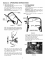
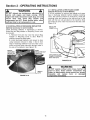
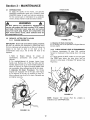
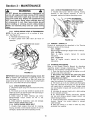
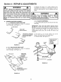
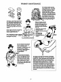
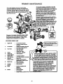
Safety Instructions & Operator's Manual for
21" STEEL DECK
WALK MOWERS
SERIES 17
MODELS
R2167517BV
RP2167517BV
RP215517HC
RP2167517B VE
WRP216517BE
MODEL NUMBER EXPLANATION
I
P I 21 167sl 17 I Bv I
l
MODEL DESIGNATION
SELF-PROPELLED
CUTTING WIDTH
R - Recycling Model
P - Self Propelled Model
W - Model Designation
21 - 21" Cutting Width
55 - 5.50 HP (Engine Horse Power)
675 - 6.75 HP (Engine Horse Power)
17 - Series Designation
B - Briggs & Stratton
V- Over Head Valve
E - Electric Start
ENGINE DESIGNATION
SERIES DESIGNATION
ENGINE HORSE POWER
H - Honda
C - Over Head Cam
Thank you for buying a SNAPPER Product! Before operating your Walk Behind, read this manual carefully and
pay particular attention to the "IMPORTANT SAFETY INSTRUCTIONS" on Pages 2 & 3. Remember that all
power equipment can be dangerous if used improperly. Also keep in mind that SAFETY requires careful use in
accordance with the operating instructions and common sense.
8NAPPERo
McDonough, GA., 30253
U.S.A.
COPYRIGHT © 2002
SNAPPER INC.
ALL RIGHTS RESERVED
MANUAL No. 7-4933 (Rev 1, 6/22/04)
IMPORTANT
SAFETY INSTRUCTIONS
WARNING: This powerful cutting machine is capable of amputating hands and feet and can throw objects that
can cause injury and damage! Failure to comply with the following SAFETY instructions could result in serious
injury or death to the operator or other persons. The owner of the machine must understand these instructions
and must allow only persons who understand these instructions to operate machine. Each person operating
the machine must be of sound mind and body and must not be under the influence of any substance, which
might impair vision, dexterity or judgment. If you have any questions pertaining to your machine which your
dealer cannot answer to your satisfaction, call or write the Customer Service Department at SNAPPER,
McDonough, Georgia 30253. Phone: (1-800-935-2967).
PROTECTION
FOR CHILDREN
Tragic accidents can occur if the operator is not
alert to the presence of children. Children are often
attracted to the machine and the mowing activity.
Never assume that children will remain where you
last saw them.
1.
2.
3.
4.
5.
6.
KEEP children out of the mowing area and
under the watchful care of a responsible adult.
DO NOT allow children in yard when machine is
operated and turn machine OFF if anyone
enters the area.
DO NOT allow pre-teenage children to operate
machine.
ALLOW only responsible adults & teenagers
with
mature judgment
under close adult
supervision to operate machine.
DO NOT
pull mower
backwards
unless
absolutely necessary. LOOK and SEE behind
and down for children, pets and hazards before
and while backing.
USE EXTRA CARE when approaching blind
corners, shrubs, trees, or other objects that
may obscure vision.
SLOPE
1.
2.
3.
OPERATION
Slopes are a major factor related to slip and fall
accidents, which can result in severe injury. All
slopes require extra caution. If you feel uneasy
on a slope, DO NOT mow it.
Mow
across
slopes,
never
up-and-down.
Exercise extreme CAUTION when changing
directions on slopes. DO NOT mow steep
slopes or other areas where stability or traction
is in doubt.
Use extra care with grass catchers or other
attachments; these affect the handling and the
stability of the machine.
PREPARATION
1.
2.
Read, understand, and follow instructions and
warnings in this manual and on the mower,
engine and attachments. Know the controls and
the proper use of the mower before starting.
Only mature, responsible persons shall operate
the machine and only after proper instruction.
PREPARATION
(Continued From Previous Column)
3.
Data indicates that operators age 60 and above,
are involved in a large percentage of mowerrelated
injuries.
These
operators
should
evaluate their ability to operate the mower
safely enough to protect themselves and others
from serious injury.
4. Handle fuel with extra care. Fuels are flammable
and vapors are explosive. Use only an approved
fuel container. DO NOT remove fuel cap or add
fuel with engine running. Add fuel outdoors
only with engine stopped and cool. Clean
spilled fuel and oil from machine. DO NOT
smoke.
5. Check the area to be mowed and remove all
objects such as toys, wire, rocks, limbs and
other objects that could cause injury if thrown
by blade or interfere with mowing. Also note the
location of holes, stumps, and other possible
hazards.
6. Keep people and pets out of the mowing area.
Immediately, STOP Blade, Stop engine and Stop
mower if anyone enters the area.
7. Check shields, deflectors,
switches,
blade
controls and other safety devices frequently for
proper operation and location.
8. Make sure all safety decals are clearly legible.
Replace if damaged.
9. Protect yourself when mowing and wear safety
glasses, long pants and substantial footwear.
DO NOT mow barefooted or with sandals.
10. Know how to STOP blade and engine quickly in
preparation for emergencies.
11. Use extra care when loading or unloading the
machine into a trailer or truck.
12. Check grass catcher components frequently for
signs of wear or deterioration and replace as
needed to prevent injury from thrown objects
going through weak or torn spots.
IMPORTANT
SAFETY INSTRUCTIONS
OPERATION
1.
2.
3.
4.
5.
6.
7.
8.
9.
10.
11.
12.
13.
14.
15.
DO NOT put hands or feet near or under
rotating parts. Keep clear of discharge area
while engine is running.
STOP engine when crossing gravel drives,
walks, or roads, and under any conditions
where thrown objects might be a hazard.
Mow only in daylight or good artificial light.
DO NOT operate mower while under the
influence of alcohol or drugs.
After striking a foreign object or if mower
vibrates
abnormally,
STOP
the
engine,
disconnect and secure spark plug wire. Inspect
the mower for any damage and repair the
damage.
DO NOT mow near drop offs, ditches or
embankments. Operator could lose footing or
balance.
STAY ALERT for holes and other hidden
hazards. Tall grass can hide obstacles. Keep
away from ditches, washouts, culverts, fences
and protruding objects.
DO NOT mow on wet grass. Always be sure of
your footing. Keep a firm hold on the handle
and walk, never run. Slipping could cause
injury.
DO NOT leave the machine with the engine
running. STOP BLADE and STOP ENGINE
before leaving the operators position for any
reason.
Before cleaning, repairing or inspecting make
certain engine, blade and all moving parts have
STOPPED. Disconnect and secure spark plug
wire away from plug to prevent accidental
starting.
STOP engine and wait until the blade comes to
complete STOP before removing grass bag
and/or clearing grass.
DO NOT operate mower without the entire grass
catcher or guards in place. DO NOT point
discharge at people, passing cars, windows or
doors.
Slow down before turning.
Watch out for traffic when near or crossing
roadways.
DO NOT operate engine in enclosed areas.
Engine
exhaust
gases
contain
carbon
monoxide, a deadly poison.
MAINTENANCE
1.
AND STORAGE
DO NOT store mower or fuel container inside
where fumes may reach an open flame, spark or
pilot light such as in a water heater, furnace,
clothes dryer or other gas appliance. Allow
engine to cool before storing machine in an
enclosure. Store fuel container out of reach of
children
in a well ventilated,
unoccupied
building.
2. Keep mower and engine free of grass, leaves or
excess grease to reduce fire hazard and engine
overheating.
3. When draining fuel tank, drain fuel into an
approved container outdoors and away from
open flame.
4. Keep all bolts, especially blade bolts, nuts and
screws properly tight. Check that all cotter pins
are in proper position.
5. Always
provide adequate
ventilation
when
running engine. Engine exhaust gases contain
carbon monoxide, a deadly poison.
6. Service engine and make adjustments only
when engine is stopped. Removed spark plug
wire from spark plug and secure wire away
from spark plug to prevent accidental starting.
7. DO NOT change engine
governor
speed
settings or overspeed engine.
8. Check grass bag assembly frequently for wear
or deterioration to avoid thrown objects and
exposure to moving parts. Replace with new
bag if loose seams or tears are evident. Replace
slider or bag adapter if broken or cracked.
9. Mower blades are sharp and can cut. Wrap the
blades or wear heavy leather gloves and use
CAUTION when handling them.
10. DO NOT test for spark by grounding spark plug
next to spark plug hole; spark plug could ignite
gas exiting engine.
11. Have machine serviced
by an authorized
SNAPPER dealer at least once a year and have
the dealer install any new safety devices.
12. Use only genuine SNAPPER replacement parts
to
assure
that
original
standards
are
maintained.
TABLE OF CONTENTS
IMPORTANT SAFETY INSTRUCTIONS ......................................................................
2 -3
TABLE OF CONTENTS ......................................................................................................
4
SECTION 1 - FAMILIARIZATION .......................................................................................
5
SECTION 2 - OPERATING INSTRUCTIONS ...............................................................
6-10
Pre-start Checklist ................................................................................................
6
Starting & Stopping Engine & Blades ............................................................
6-7
Starting & Stopping Wheel Drive ........................................................................
7
Handle Height Adjustment ..................................................................................
8
Cutting Height Adjustment ..................................................................................
8
Recycling Operation .............................................................................................
9
Installation of Grass Catcher (Door Type) ...................................................
9-10
Installation of Grass Catcher (Slider Type) .....................................................
10
Installation of Discharge Deflector & Recycling Cover .................................. 11
SECTION 3 - MAINTENANCE INSTRUCTIONS .......................................................
12-13
Change Engine Oil ..............................................................................................
12
Check Transmission Grease .............................................................................
12
Check Mower Blade ...........................................................................................
13
Check Engine Drive Belt ....................................................................................
13
Check Transmission Poly-V Belt ......................................................................
13
Service - Annually ..............................................................................................
13
Engine ..............................................................................................................
13
Air Filter ............................................................................................................
13
Engine Oil .........................................................................................................
13
Storage Procedure .............................................................................................
13
SECTION 4 - ADJUSTMENTS AND REPAIR ............................................................
14-20
Mower Blade Replacement ................................................................................
14
Blade Sharpening .........................................................................................
14-15
Wheel Drive Control Adjustment ......................................................................
15
Driven and Drive Disc Service ..........................................................................
16
Cleaning Drive Disc and Driven Disc ............................................................
16
Drive Spring Repair/Replacement .................................................................
16
Driven Disc Adjustment ............................................................................
16-17
Driven Disc Replacement .........................................................................
17-18
Driven Disc Bearing Replacement ................................................................
18
Hex Shaft Bearing Replacement ....................................................................
19
Belt Service .........................................................................................................
19
Engine Drive Belt Replacement ...............................................................
19-20
Transmission Poly-V Belt Replacement .......................................................
20
Battery Service ...................................................................................................
21
TROUBLESHOOTING
......................................................................................................
22
SERVICE SCHEDULE ......................................................................................................
23
Maintenance/Replacement
Parts ......................................................................
WARRANTY ......................................................................................................................
PRIMARY MAINTENANCE
PRODUCT REGISTRATION
........................................................................................
FORM .................................................................................
23
24
25-28
29
IMPORTANT
The figures and illustrations in this manual are provided for reference only and may
differ from your specific model. Contact your Snapper dealer if you have questions.
Section 1 - FAMILIARIZATION
WHEEL DRIVE
CONTROL
BRIGGS
ENGINE
SPEED
CONTROL
BLADE
CONTROL
_
HONDA
ENGINE
SPEED
CONTROL
GROUNDSPEED
CONTROL
CHOKE
FAST
IGNITION KEY
FAST
ROPE START
HANDLE
SLOW
SLOW
FUEL FILLER
CAP
OIL FILL CAP
AND DIPSTICK
ENGINE
PRIMER
REAR HEIGHT
ADJUSTMENT
LATCH
GRASS BAG
ADAPTER
FIGURE 1.1
1.1 INTRODUCTION
This manual has been prepared for the operators of
the SNAPPER
WALK BEHIND
MOWERS.
Its
purpose, aside from recommending operating and
routine service requirements, is to promote safety
through the use of accepted operating practices.
Read, Understand
and Follow the "IMPORTANT
SAFETY INSTRUCTIONS" on Pages 2 & 3 of this
manual and all safety messages on the mower and
attachments before operating the mower.
1.2 NOMENCLATURE
The nomenclature drawing above, Figure 1.1, shows
the essential parts of the SNAPPER WALK BEHIND
MOWERS.
It is recommended that all operators of
the mower become thoroughly familiar with the
controls, parts and operation of the mower before
operating.
Specific details involving the engine are
found in the separate engine owner's manual. Study
these manuals before operating and keep both
handy for future reference.
Section 2 -OPERATING
2.1
INSTRUCTIONS
PRE-START CHECK LIST
Make the following checks and perform the service
required before each start-up.
2.1.1. Check guards, deflectors, grass bag, adapter
and covers to make sure all are in place and
securely tightened.
2.1.2. Check blade control and wheel drive control
to insure they work freely. See Figure 2.1.
BLADE
CONTROL
2.2
STARTING & OPERATION
2.2.1. ENGINE & BLADE
(Primer Models)
1. Move engine speed control to the "Fast" (Rabbit)
position. See Figure 2.3.
IMPORTANT:
Certain models do not have a
separate engine speed control. These models have
a fixed non-adjustable engine speed. Proceed to
step 2 and prime engine to start.
NOTE: Stop the engine (and blade) by releasing
blade control.
ROPE START
HANDLE
WHEEL
DRIVE
CONTROL
ENGINE SPEED
FIGURE 2.1
the
BLADE
CONTROL
IGNITION
KEY
CONTROL
2.1.3. Check cutting height. Adjust to desired height.
2.1.4. Check engine oil and add oil as needed to bring
level up to the full mark. Refer to Engine Owner's
Manual for oil specifications. See Figure 2.2.
ENGINE SPEED CONTROL
(SHOWNIN FAST POSITION)
FIGURE 2.3
2. Push primer button three times to start a cold
engine. NOTE: The primer should not be required to
restart a warm engine. See Figure 2.4
3. Pull blade control against handle.
4. Pull rope start handle to crank engine.
5. After engine starts allow a brief warm-up until
engine runs smooth.
PRIMER
FIGURE 2.2
2.1.5. Add fuel to tank after pushing the mower
outside where fumes can safely dissipate. Make sure
cap is tightened after refueling. Refer to Engine
Owners Manual for specifications.
2.1.6. Clean exterior surfaces of cutting deck and
engine of any accumulation of spilled fuel, dirt, grass,
oil, etc. Keep engine air intake screen and cooling
fins clear at all times.
FIGURE 2.4
Section 2 -OPERATING
2.2
INSTRUCTIONS
STARTING & OPERATION
2.2.1. ENGINE & BLADE
(Choke Models)
1. Move fuel shut off valve to the "ON" position.
See Figure 2.5.
NOTE:
Stop the engine (and blade) by releasing
blade control.
the
5. After engine starts, allow a brief warm-up until
engine runs smooth.
2.2
STARTING & OPERATION
2.2.1. ENGINE & BLADE
(Electric Start Models)
When the ignition key (Electric Start Switch) is turned
to "START", the engine will not crank and will not start
unless the blade control is engaged!
1. Move engine speed control to the "Fast" (Rabbit)
position. See Figure 2.3.
2. Push primer button three times to start a cold
engine. NOTE: Primer should not be required to
restart a hot engine.
3. Pull blade control against handle.
4. Turn key to the start position until engine starts.
See Figure 2.3.
NOTE: If after 5 seconds of cranking the engine does not
start, release the key and attempt starting again after
waiting for approximately 20 seconds.
5. After engine starts, allow a brief warm-up until
engine runs smooth.
2.2.2.
PROPELLING MOWER
(Self Propelled Models Only)
1. Start engine. Refer to Section "Starting &
Operation".
2. Move ground speed control to the desired speed
position. See Figure 2.7.
3. Move wheel drive control against handle to
engage wheel drive and propel mower forward.
Forward speed can be adjusted while the mower is
moving by changing position of the ground speed
control. See Figure 2.7.
FIGURE 2.5
2. Move engine speed
position. See Figure 2.6.
control
to the "Choke"
MOVE TO
CHOKE
POSITION
GROUND
SPEED
CONTROL
SHOWNIN
WHEEL
DRIVE
CONTROL
ENGINE
SPEED
CONTROL
FIGURE 2.7
2.3
FIGURE 2.6
.
4.
Pull blade control against handle.
Pull rope start handle to crank engine.
STOPPING
Stop engine and blade by releasing the blade
control. Stop forward motion of mower by releasing
the wheel drive control.
Section 2 -OPERATING
2.4
INSTRUCTIONS
HANDLE HEIGHT ADJUSTMENT
The height of the mower handle can be adjusted as
follows:
1. Loosen the lower nuts on each lower handle as
shown in Figure 2.8.
2.5
CUTTING HEIGHT ADJUSTMENT
2. Set all wheels at the same cutting height. The
highest cutting position is Notch 6. The lowest
cutting position is Notch 1. See Figure 2.10.
HIGHER
LATCH
POSITION
LOWER
HANDLE
LOWER
CUTTING HEIGHT SETTINGS
LOOSEN LOWER
NUTS ON EACH
LOWER HANDLE
/J
FIGURE 2.10
//
FIGURE 2.8
2. Move upper mower handle up or down until the
desired position is achieved.
3. Tighten the lower nuts on each lower handle to
maintain desired position.
WARNING
Stop engine and mower blade by releasing the blade
control before adjusting cutting height.
2.5
CUTTING HEIGHT ADJUSTMENT
1. Pull the height adjusting latch outward and move
to desired cutting height. See Figure 2.9.
D
LOWEST CUTTING
/
LATCH
/
HIGHEST
CUTTING
HEIGHT
FIGURE 2.9
Section 2 -OPERATING
INSTRUCTIONS
WARNING
DO NOT attempt any maintenance, adjustments or
servicewith engine and blade running.STOP engine
and blade.Disconnect spark plug wire and secure
away from spark plug. Engine and components are
HOT. Avoid serious burns, allow sufficient
time for
allcomponents to cool.
2.8 INSTALLATION of RECYCLING PLUG
(Optional Accessory on Some Models)
STEP 1 : Once adapter has been installed, recycling may
be desired. Insert recycling plug completely and securely
into adapter. Install grass bag. See Figure 2.12.
INSERT RECYCLING PLUG
COMPLETELY AND SECURELY
INTO ADAPTER. INSTALL
GRASS BAG.
2.6 RECYCLING OPERATION
NOTE: For best recycling results, cut up to a maximum of
1/3 of grass blade length and recycle ONLY when grass
is dry.
1. Set all wheels in the highest cutting position
(Notch 6).
2. Move engine speed control to "FAST" (Rabbit)
position.
3. Move ground speed control to slowest speed
setting.
4. Proceed mowing slowly. If grass is very dense,
lower each rear wheel latch one notch lower than
the front wheel latches to improve
recycling
performance.
2.7
INSTALLATION
PLUG
of GRASS BAG ADAPTER
(Optional accessory on some models)
STEP 1: Install the grass bag adapter and secure to the
side and top of the deck with the two nuts provided on the
machine. Slot in front edge of adapter must be under nut
located on top of deck. See Figure 2.11.
FIGURE 2.12
2.9
INSTALLATION
of GRASS CATCHER
(Optional accessory on some models)
Install grass catcher by sliding connector over flange
of adapter. See Figure 2.13. Attach grass bag hooks
over middle handle cross bar. See Figure 2.14.
SECURE ADAPTER
TO DECK WITH NUTS
POSITION BAG
BETWEEN
SLIDE
CONNECTOR
DOWN OVER BAG
ADAPTER FLANGE
SECURE
WITH NUTS
\
BAG
ADAPTER
ADAPTER
FIGURE 2.11
FIGURE 2.13
(Continued On Next Page)
Section 2 -OPERATING
INSTRUCTIONS
HOOK BAG HANDLE
OVER LOWER
HANDLES
WARNING
DO NOT attempt any maintenance, adjustments or
service with engine and blade running. STOP engine
and blade. Disconnect spark plug wire and secure
away from spark plug. Engine and components are
HOT. Avoid serious burns, allow sufficient time for
all components to cool.
2.9
INSTALLATION of GRASS CATCHER
(Optional accessory on some models)
SLIDE
OVER END OF
ADAPTER FLANGE
MIDDLE
HANDLE
CROSS
BAR
ATTACH BAG HOOKS
OVER MIDDLE HANDLE
CROSS BAR
FIGURE 2.16
2.11 REMOVING and DUMPING GRASS CATCHER
1. Grasp bag connector and bag handle as shown.
See Figure 2.15.
2. First, lift up on bag handle, removing it from the
mower handle. Then lift up on bag connector
removing it from the adapter flange.
3. Dump bag by pulling bag slider off of Z-Fold at
rear of bag, opening bag.
4. To close bag, fold rear of bag into Z-shape,
keeping edges aligned. Note: an illustration of
folding the Z-shape is attached to the bag.
5. Grasp the edge of the Z-fold, and while holding
the slider, pull the Z-fold fully into the slider. See
Figure 2.17.
FIGURE 2.14
2.10 INSTALLATION of GRASS CATCHER
(Slide Closure Type)
1. Position grass bag between handles. See
Figure 2.15. Install grass catcher by sliding
connector over flange of adapter. Attach grass
bag hooks over middle handle cross bar. See
Figure 2.16.
LOWER HANDLES
GRASP SLIDER. PULL
Z-FOLD INTO SLIDER
APTER
/
FIGURE 2.17
FLANGE
FIGURE 2.15
10
Section 2 -OPERATING
INSTRUCTIONS
2.11 INSTALLATION of RECYCLING COVER
(Optional Accessory on Some Models)
It will be necessary to remove bag adapter and grass
bag or discharge deflector before installing recycling
cover. See previous section for instructions. Install the
recycling cover and secure to the side and top of the
deck with the two nuts provided on the machine. Slide
top portion of cover under nut secured to the deck. See
Figure 2.19.
WARNING
DO NOT attempt any maintenance, adjustments or
service with engine and blade running. STOP
engine and blade.Disconnect spark plug wire and
secure away from spark plug. Engine and
components are HOT. Avoid serious burns, allow
sufficient
time forallcomponents to cool.
2.10 INSTALLATION
of DISCHARGE
DEFLECTOR
RECYCLING
COVER
(Optional accessory on some models)
Install discharge deflector if discharging is desired.
Grass Bag and Bag Adapter or Recycling Cover must
be removed.
1. Remove front and rear nuts that secure Bag
Adapter or Recycling Cover to deck. Refer to
sections concerning these parts.
2. Install discharge deflector and secure to deck
using hardware removed in Step 1. Slot in front
edge of discharge deflector must be under nut as
shown and both bolts protruding through holes in
the side of the deflector. See Figure 2.18.
INSTALL
DISCHARGE
DEFLECTOR
SLIDE
DEFLECTOR SLOT
UNDER NUT
ATTACH RECYCLING
COVER TO THE DECK
WITH TWO NUTS
FIGURE 2.19
WARNING
L
DO NOT operate without entireGrass Catcher or
guard in place. Grass Catcher components are
subject to deterioration
during normal use. Inspect
frequently and
replace worn
or damaged
components immediately.
INSTALL
FIGURE 2.18
11
Section 3- MAINTENANCE
3.1
HONDA ENGINE
INTRODUCTION
To retain the quality of the mower, use genuine
SNAPPER replacement parts only. Contact a local
SNAPPER dealer for parts and service assistance.
For the correct part or information for a particular
mower, always mention model and serial number.
WARNING
DO NOT attempt any maintenance,
adjustments
or
service with engine and blade running. STOP engine
and blade. Disconnect
spark plug wire and secure
away from spark plug. Engine and components
are
HOT. Avoid serious burns, allow sufficient time for
all components to cool.
3.2
OIL FILL
CAP
SERVICE - AFTER FIRST 5 HOURS
3.2.1. CHANGE ENGINE OIL
FIGURE 3.1B
4. Dispose of drain oil properly.
5. Fill engine with oil as specified in Engine Manual.
Do Not overfill.
IMPORTANT: Drain fuel tank before tipping machine.
DO NOT tip machine with carburetor or spark plug down.
Oil from crankcase will saturate the air filter and cause the
engine to be hard to start or not start at all. If
contamination does occur, the air filter will have to be
replaced.
3.2.2. CHECK GREASE LEVEL IN TRANSMISSION
1. Remove transmission fill plug. Roll machine
forward or backward while looking down into plug
hole.
2. If liquid grease IS NOT visible on the input gear
(the small gear below the plug hole), add an
amount, to cover gear, of Snapper "00" grease. See
Figure 3.2.
1. Refer
to Engine
Manual for
proper
oil
specifications,
procedures
and
proper
service
intervals.
2. For simplest/cleanest oil change, loosen lower
handle nuts. Remove two of the four bolts and fold
handles. Stand mower up on lower handle brackets as
shown in Figure 3.1A. Drain oil through dipstick tube
into a container. Allow sufficient time for all oil to drain.
3. Alternate
Oil Drain: Procedure:
The Honda
engines are equipped with oil fill caps. See Figure
3.1.B. Remove oil fill cap, tip machine to drain oil.
Allow sufficient time for all oil to drain. Reinstall cap
and tighten securely.
/
FILL PLUG
FIGURE 3.2
NOTE: Snapper "00" Grease (Part
available at your SNAPPER dealer.
FIGURE 3.1A
12
No. 2-9443)is
Section 3- MAINTENANCE
3.2.5. CHECK TRANSMISSION POLY-V BELT
1. Visually check poly-v belt for cracking, fraying,
severed or belt strands exposed. If worn or
damaged, replace belt before operating mower.
WARNING
DO NOT attempt any maintenance, adjustments or
service with engine and blade running. STOP engine
and blade. Disconnect spark plug wire and secure
away from spark plug. Engine and components are
HOT. Avoid serious burns, allow sufficient time for
all components to cool. Wear heavy leather gloves
when handling or working around cutting blades.
Blades are extremely sharp and can cause severe
injury.
RECOMMENDED
BLADE RETAINING
CAP SCREW TORQUE
SHOULD BE
40 FT. LBS.
\l
3.2.2. CHECK GREASE LEVEL IN TRANSMISSION
NOTE: Do not spill grease or oil on surface of drive
disc. See Figure 3.3.
3. Reinstall transmission plug.
4. Check grease level after each 25 hours of
operation.
/
/
FIGURE 3.4
3.3 SERVICE -ANNUALLY
Perform all maintenance as described in the "Service
Schedule" section of this manual.
3.3.1. Engine
Service engine according to engine owner's manual.
3.3.2. Air Filter
Refer to engine owner's manual for service
instructions.
3.3.3. Engine Oil
Refer to engine owner's manual for service
instructions.
KEEP DRIVE DISC CLEAN!
3.4 STORAGE PROCEDURE
Refer to the Engine Owner's Manual for directions
regarding engine storage preparations.
Prepare the
mower for "end of season" storage as follows:
1. Drain fuel from fuel tank and let engine run until
all fuel is out of the carburetor.
2. Disconnect and remove the spark plug wire
away
from
spark
plug
before
any other
preparations are made!
3. Tape all openings closed to prevent spraying
water into exhaust or air intakes during washing.
4. Tilt mower up on its rear wheels and thoroughly
clean the underside of the deck. Do not tilt mower
with spark plug or carburetor down. Scrape away
any accumulation of grass with a putty knife and or
wire brush.
5. Lubricate all exposed metal with a light coating
of oil to prevent corrosion.
6. On self-propelled
models disconnect transfer
rod clip and remove ground speed control rod
before folding handles.
7. Loosen handle knobs. Carefully fold the handles
forward, "flexing" the control cables to prevent
cable damage.
8. Store the mower in a shed or other dry area,
protected from weather.
FIGURE 3.3
IMPORTANT: Drain fuel tank before tipping mower. DO
NOT tip machine with carburetor or spark plug down. Oil
from crankcase will saturate the air filter and cause the
engine to be hard to start or not start at all. If contamination
does occur, the air filter will have to be replaced.
3.2.3. CHECK MOWER BLADE
1. Disconnect spark plug wire and secure end away
from plug.
2. Tilt mower up on its rear wheels for access to the
blade cap screw. Do not tilt mower with spark plug or
carburetor down. See Figure 3.4.
3. Check torque of blade retaining cap screw.
Recommended
torque should be 40 ft. Ibs.
See Figure 3.4.
4. Check blade for sharpness, wear and damage.
Refer to Section "Blade Wear Limits".
3.2.4. CHECK ENGINE DRIVE BELT
1. Visually check engine drive belt for cracking,
fraying, severed or belt strands exposed. If worn or
damaged, replace belt before operating mower.
13
Section 4 - REPAIR & ADJUSTMENTS
2. Replace the blade if it is badly chipped, bent,
noticeably out of balance or has cracks or notch in
either tip. See Figure 4.1 & 4.1A. Replace with new
blade.
WARNING
DO NOT attempt any maintenance, adjustments or
service with engine and blade running. STOP engine
and blade. Disconnect spark plug wire and secure
away from spark plug. Engine and components are
HOT. Avoid serious burns, allow sufficient time for
all components to cool. Wear heavy leather gloves
when handling or working around cutting blades.
Blades are extremely sharp and can cause severe
injury.
4.1
WARNING
DO NOT use a cutting blade that shows signs of
excessive wear or damage. Refer to Section
"MOWER BLADE REPLACEMENT" for proper blade
inspection and service procedures.
MOWER BLADE REPLACEMENT
4.1.1. STANDARD BLADE WEAR LIMIT
1. Inspect blade frequently for signs of excessive
wear or damage. See Figure 4.1.
F
4.1.2. BLADE SHARPENING
1. Disconnect spark plug wire and secure end away
from plug.
IMPORTANT: Drain fuel tank before tipping mower.
DO NOT tip machine with carburetor or spark plug down.
Oil from crankcase will saturate the air filter and cause the
engine to be hard to start or not start at all. If
contamination does occur, the air filter will have to be
NEW BLADE
--..._
177
WEAR LIMIT
--..2//
[.----(NOTCH
._
"_'_
•
_
"_'_-.--J__/_
"_'="
STARTS)
replaced.
DANGEROUS
CONDITION! 2. Tilt mower up on its rear wheels. Do not tilt
DO NOT USE ON MOWER v
• mower with spark plug or carburetor down.
,-'REPLACE
WITH NEW
,,_BLADE....
..........
3.
Nemove
Dlaae.
_ee
i-lgure
_..5.
! _
"I-___
MAKE SURE THAT
BLADE HUB IS
SEATED
"_
FIGURE 4.1
BLADE
BETWEEN
HUB
FLANGES
...
4.1.1.A. NINJA BLADE WEAR LIMIT
1. Inspect blade frequently for signs of excessive
wear or damage. See Figure 4.2.
WEAR LIMIT.
CRACKS OR
NOTCHES
BEGIN TO
APPEAR ON TIP
NEW BLADE
///"f_l
_,_BLADE
J_)"_"_
i_-_
ji
CONE W-ASHI_
(C°n cave:id
_)SC
FIGURE 4.3
DANGEROUS!
DO NOT USE A BLADEIN
THIS CONDITION!
FIGURE 4.2
14
!
R/EW
i
I_J
Section 4 - REPAIR & ADJUSTMENTS
WARNING
CLUTCH CABLE
VINYL SPRING
DO NOT attempt any maintenance, adjustments or
servicewith engine and blade running.STOP engine
and blade.Disconnect spark plug wire and secure
away from spark plug. Engine and components are
HOT. Avoid serious burns, allow sufficient
time for
allcomponents to cool.
1/16" TO 1/8"
CLEARANCE
CLUTCH CABLE
UPPER
SPRING
SPRING HOOK
LOWER
SPRING
4. Sharpen blade on a grinding wheel at an angle of
22 to 28 degrees. DO NOT sharpen blade beyond
original cutting edge. See Figure 4.4.
DO NOT SHARPEN
BEYOND ORIGINAL
CUTTING EDGE
CABLE
EYE
BLADE TIP
J
•
.J
_._._._
//"
/
/
END VIEW OF
BLADE ASSEMBLY
ORIGINAL CUTTING
EDGE
FIGURE 4.5
FIGURE 4.4
2. To adjust, unhook upper
and rotate spring in direction
shorten spring length.
3. Rehook upper spring to
clearance. Repeat procedure
5. Check blade for balance. If necessary, correct
balance by grinding heavy end of blade.
6. Reinstall blade. See Figure 4.3. Check torque of
blade retaining cap screw. Recommended torque
should be 40 ft. Ibs.
cable eye and check
if required.
NOTE: The vinyl spring cover should be kept over the
spring at all times except for adjustments.
NOTE: The following
sections 4.2 through
4.4 are for self-propelled
models only.
4.2
spring from cable eye
required to extend or
4. If the wheel drive control fails to return quickly to
the "OFF" position when released, check for binding
at the cable holdings located on the side of the right
handle. The upper clip should be located 2" below
the upper knob; the lower clip should be 4" above
the lower knob. The cable should slide freely with
the clips installed at these locations.
WHEEL DRIVE CONTROL ADJUSTMENT
1. The wheel drive control is properly adjusted
when there is 1/16" to 1/8" clearance between the
inside of the spring hook and the inside of the clutch
cable eye with the wheel drive control released. See
Figure 4.5.
15
Section 4 - REPAIR & ADJUSTMENTS
USE
NEEDLE
NOSE
WARNING
DO NOT attempt any maintenance, adjustments or
servicewith engine and blade running.STOP engine
and blade.Disconnect spark plug wire and secure
away from spark plug. Engine and components are
HOT. Avoid serious burns, allow sufficient
time for
allcomponents to cool.
4.3
DRIVEN AND DRIVE DISC SERVICE
If the mower does not propel itself properly, See
Figure 4.6. Check for the following problems:
DRIVEN DISC &
RUBBER RING
POLY-V
DRIVE
SPRING
ENGINE
DRIVE
BELT
FIGURE 4.7
DRIVE
DISC
4.3.3. DRIVEN DISC ADJUSTMENT
If the drive disc and driven disc are clean and the
mower drive is still slipping, adjust the driven disc as
follows:
1. Place ground speed control in the number six
speed position. See Figure 4.8.
FIGURE 4.6
MOVE GROUND
SPEED CONTROL TO
SIXSPEEDPOSITION
1. Grease on drive disc causing slippage.
2. Broken or disconnected drive spring.
3. Driven disc is out of adjustment.
4. Driven disc rubber is worn - does not contact
drive disc properly.
5. Worn Poly-V Belt or engine drive belt.
REYCLING M_[_L
SIXTH SPEED
POSITION
NOTE: If any of the above (1 thru 5) are causing
problems, service as follows:
4.3.1. Cleaning Drive Disc & Driven Disc.
If oil or grease on the drive disc or driven disc is
causing slippage, clean discs as follows:
1. Wipe away any oil or grease with a clean cloth.
2. Use either an approved grease solvent or hot,
soapy water to clean drive disc or driven disc.
3. Rinse components with clean water.
4. Dry components with a clean cloth.
FIGURE 4.8
4.3.2. Drive Spring Repair/Replacement
If drive spring is loose, reconnect as shown in Figure
4.7. If spring is broken, replace with new spring.
IMPORTANT:
If machine
drive system
slipping see Trouble Shooting section.
continues
16
_
SHOWN
(ROPE START MOUNTED ON
RIGHT SIDE OF HANDLE)
Section 4 - REPAIR & ADJUSTMENTS
WARNING
1/8"MEASUREMENT
TO
EDGE OFDRIVE
DISC
DO NOT attempt any maintenance, adjustments or
service with engine and blade running. STOP engine
and blade. Disconnect spark plug wire and secure
away from spark plug. Engine and components are
HOT. Avoid serious burns, allow sufficient time for
all components to cool.
DRIVE
DISC
SLIDE DRIVEN
DISC ASSEMBLY
TOWARD OUTSIDE
EDGE
4.3.3.
DRIVEN DISC ADJUSTMENT
(Continued From Previous Page)
2. Remove driven disc spring from driven disc
assembly. Loosen connector hex nut. See Figure
4.9.
TRANSFERFz:ZI_
OUTSIDE
EDGE
DRIVEN DISC
ASSEMBLY
DRIVE
DISC
HEX NUT
FIGURE 4.10
DRIVEN DISC
SPRING
CONNECTOR
CLIP
TRANSFER--_
ROD
CONNECTOR
ROD
SPEED
CONTROL
ROD
HEX NUT
FIGURE 4.9
3. Slide driven disc assembly over to 1/8" from
outside edge of drive disc. Maintaining the 1/8"
measurement,
remove any looseness from the
linkage. This can be done by holding the transfer
rod and applying pressure to the left (as viewed
from operators
position).
Then retighten
the
connector hex nut securely. See Figure 4.10. Move
ground speed control to the first speed position,
then back to the sixth speed position. Recheck the
1/8" measurement described previously. Reinstall
driven disc spring to driven disc assembly.
I
REINSTALLED CLIP
AND TRANSFER ROD
I
CONNECTOR
CLIP
I
FRANSFER
ROD
SPEED
CONTROL
ROD
4.3.4. Replacing Rubber Driven Disc
If the rubber is badly chunked or worn it must be
replaced. Install new Driven Disc as follows:
1. Using a small fiat blade screwdriver, free the clip
from the transfer rod. Then remove the transfer rod
from the clip and the speed control rod. See Figure
4.11.
FIGURE 4.11
17
Section 4 - REPAIR & ADJUSTMENTS
4.3.5. Replacing Bearing In Driven Disc Assembly
IMPORTANT:
The bearing, on these machines, is
staked into the thrust plate. The bearing will have to be
driven out with a mallet and a large punch. A new
bearing with four retaining screws will have to be
purchased to replace existing bearing.
If the driven disc bearing requires replacement,
remove the driven disc assembly and replace
bearing as follows:
1. Using a small flat blade screwdriver, free the clip
from the transfer rod. Then remove the transfer rod
from the clip and the speed control rod. See Figure
4.11.
2. Using needle nose pliers, unhook the drive
spring and slide the driven disc assembly off the
hex shaft. See Figure 4.12.
3. Remove both snap rings that secure rubber
driven disc hub to thrust plate. See Figure 4.13.
4. Slide the rubber driven disc hub out of the
bearing.
5. Drive out existing bearing.
6. Install new bearing and secure to thrust plate
with four retaining screws. Tighten screws securely.
7. Reassemble components in reverse order.
WARNING
DO NOT attempt any maintenance, adjustments or
servicewith engine and blade running.STOP engine
and blade. Disconnect spark plug wire and secure
away from spark plug. Engine and components are
HOT. Avoid serious burns, allow sufficient
time for
allcomponents to cool.
4.3.4.
Replacing Rubber Driven Disc
(Continued from previous page)
2. Using needle nose pliers, unhook the drive
spring and slide the driven disc assembly off the
hex shaft. See Figure 4.12.
3. Remove the two snap rings which secure the
rubber driven disc to the driven disc assembly. See
Figure 4.13.
4. Install new rubber driven disc onto driven disc
assembly with retaining rings.
5. Reverse above procedures for reassembly and
installation of driven disc assembly.
O
FIGURE 4.13
FIGURE 4.12
18
Section 4 - REPAIR & ADJUSTMENTS
j_
WARNING
4.4 BELT SERVICE
On self-propelled mowers, the engine belt transmits
power from engine to drive disc. The drive disc
powers the poly-v belt, which engages the
transmission that powers the rear wheels. Should
these belts become worn, they could cause slippage,
which would impair mower performance.
The
condition of the engine belt and poly-v belt should be
checked after every 25 hours of mower operation.
_,
DO NOT attempt any maintenance, adjustments or
servicewith engine and blade running.STOP engine
and blade. Disconnect spark plug wire and secure
away from spark plug. Engine and components are
HOT. Avoid serious burns, allow sufficient
time for
allcomponents to cool.
4.3.6. Replacement Of Bearing On Pulley End Of
Hex Shaft
To replace the bearing on the pulley end of the hex
shaft, proceed as follows:
1. Hold the hex shaft with an adjustable wrench
held next to the pulley.
2. Remove the 3/8" hex lock nut, which is located
on the outside of the right wheel bracket.
See
Figure 4.14.
3. Remove holder, O-ring and bearing.
4. Install new bearing.
5. Carefully install new O-ring over the outside of the
new bearing.
6. Install bearing holder and secure with screws.
7. Install 3/8" hex lock nut.
4.4.1.
Engine Drive Belt Replacement
(Stretch Type Belts)
1. Empty the fuel tank.
2. Note the belt routing in Figure 4.15. There is no
idler pulley on these models to disconnect. See
Figure 4.15.
/
o
DRIVE BELT
,,";4'-I I
\\ %
rx',
Lo ,wo, c
/111
TOP VIEW OF STRETCH TYPE BELT ROUTING
FIGURE 4.15
7/--'7,BALL BEARING
3/8"
LOCK NUT
BALL BEARING
HOLDER
FIGURE 4.14
19
Section 4 - REPAIR & ADJUSTMENTS
PULLEY POSITION
WARNING
DO NOT attempt any maintenance, adjustments or
servicewith engine and blade running.STOP engine
and blade.Disconnect spark plug wire and secure
away from spark plug. Engine and components are
HOT. Avoid serious burns, allow sufficient
time for
allcomponents to cool.
4.4.1.
DRIVE DISC
SLOT IN END
OF DRIVE DISC
BOLT
BUSHING
Engine Drive Belt Replacement
(Stretch Type Belts)
(Continued From Previous Page)
DECK BRACKET
IMPORTANT: Drain fuel tank before tipping mower.
DO NOT tip machine with carburetor or spark plug down.
Oil from crankcase will saturate the air filter and cause the
engine to be hard to start or not start at all. If
contamination does occur, the air filter will have to be
replaced.
(PARTIALLY
SHOWN)-"_
_
BOLT RETAINER
_-_ _?>_NuTLOCK
WASHER
I
3. Remove the driven disc.
Refer to Section
"Replacing Rubber Driven Disc" for driven disc
assembly removal procedure.
4. Tilt mower up on its rear wheels and remove
blade and blade hub. Assistance from another
person may be necessary to hold mower in the tilted
position.
5. Hold the slotted end of the drive disc bolt with a
screwdriver and remove the nut and internal tooth
lock washer. See Figure 4.16.
6. Remove the belt cover located under deck.
FIGURE 4.16
4.4.2. Transmission Poly-V Belt Replacement
1. Remove the driven disc. Refer to Section on
"Replacing Driven Disc Rubber Ring" for procedure.
2. Note the routing of the old belt around the three
pulleys before removing it. See Figure 4.17.
3. Place new Poly-V Belt over end of hex shaft and
onto driven pulley.
4. Work belt onto top of idler pulley.
5. Twist belt sideways and pull it upward between
the differential bracket and drive pulley and then
down into the pulley groove. Make sure the Poly-V
Belt is above belt guide. See Figure 4.17.
7. Lift the drive disc up and remove worn belt.
8. Loop one end of new belt over engine pulley and
insert the other end through slot in deck.
See Figure 4.15.
9. Loop the belt around the pulley on the bottom of
the drive disc.
10. Reinstall drive disc and retaining hardware.
IMPORTANT: 1) The square shoulder of the drive
disc bolt must fit into the square hole of the bushing.
2) The square end of bushing must fit into the
bracket slot.
IDLER
DRIVE
PULLEY
11. Reinstall belt cover and tighten bolts securely.
12. Reinstall
blade
hub
and
cutter
blade.
Recommended torque for blade cap screw is 40 ft. Ibs.
BRACKET
HEX SHAFT
BELT GUIDE
DRIVEN
PULLEY
ROUTING OF POLY-V BELT
FIGURE 4.17
20
Section 4 - REPAIR & ADJUSTMENTS
4.5. BATTERY SERVICE
4.5.1. NEW BATTERY PREPARATION
1. Remove battery from carton.
2. Place battery in a well ventilated area on a level
non-concrete surface.
3. Remove battery cell caps. Fill cells as required with
electrolyte (purchased separately) to proper level. Fill
to 3/16" above cell plates. Filling battery with
electrolyte will bring the battery to 80% charged state.
4. With cell caps removed, connect battery charger to
battery terminals; RED to positive (+) and BLACK to
negative (-) terminal.
4.5.2. BATTERY SERVICE
1. Remove battery.
2. Place battery in a well ventilated area on a level
surface.
3. Using distilled water, refill cells as required to cover
cell plates of which can also be visualized through the
plastic battery case.
4. With cell caps removed, connect battery charger to
battery terminals. Red to positive (+) terminal and
black to negative (-) terminal.
5. Slow charge battery at 1 amp for 10 hours.
6. If battery will not accept charge or is partially
charged after 10 hours of charging at 1 amp, replace
with new battery.
IMPORTANT: 3/16" above cell plates is the recommended
level. However do not try to measure this dimension. Never
place anything in battery other than specified electrolyte.
4.5.3. BATTERY STORAGE
If Walk Behind is to be stored out of season on its rear
bumper, it is recommended the battery be removed,
charged and stored.
1. Remove battery.
2. Perform battery service.
3. Bring battery to full charge, if required.
4. Store battery in an area away from the Walk
Behind on a wood surface. DO NOT STORE
BATTERY ON A CONCRETE SURFACE.
5. Slow charge the battery at 1 amp for 2 hours to
bring the battery to full charge.
6. After charging, check level of electrolyte and add
as needed to bring level to 3/16" above cell plates.
7. Reinstall cell caps.
8. Install battery into power unit.
9. Connect positive (+) cable (red) first, from wiring
harness to the positive terminal (+) on battery using
bolt and nut provided in hardware bag. Connect
negative (-) cable (black) last, to negative terminal (-)
on battery using bolt and nut. Apply a small amount of
grease over terminals to prevent corrosion.
4.5.4. BATTERY TESTING
There are two types of battery tests: Unloaded and
Loaded. The unloaded test is the procedure that will
be discussed. It's the simplest and most commonly
used. An unloaded test is made on a battery without
discharging current. To perform unloaded testing,
check charge condition using either a hydrometer or
voltmeter.
WARNING
DO NOT over fill battery with electrolyte. Shield the
positive terminal with terminal cover located on battery
harness. This prevents
metal from touching
the
positive terminal, which could cause sparks. The
electrolyte
(acid) produces a highly explosive gas.
Keep all sparks, flame and fire away from area when
charging
battery or when handling electrolyte
or
battery. Electrolyte (acid) is a highly corrosive liquid.
Wear eye protection. Wash affected areas immediately
after having eye or skin contact with electrolyte (acid).
Battery acid is corrosive. Rinse empty acid containers
with water and mutilate before discarding. If acid is
spilled on battery, bench, or clothing, etc., Flush with
clear water and neutralize with baking soda. Never
attempt to charge battery while installed on the walk
behind. Never use "BOOST" chargers on the battery.
4.5.4.
1. Using a voltmeter, voltage readings appear
instantly to show the state of charge. Remember to
hook the positive lead to the battery's positive
terminal, and the negative lead to the negative
terminal.
2. A hydrometer measures the specific gravity of
each cell. The specific gravity tells the degree of
charge; generally, a specific gravity of about 1.265 to
1.280 indicates full charge. A reading of 1.230 to
1.260 indicates the battery should be charged. The
chart on the next page shows the charge level as
measured
by syringe float hydrometer,
digital
voltmeter and five ball hydrometer.
BATTERY TESTING
Methods
State of Charge
100% Charged w/Sulfate
100% Charged
75% Charged
50% Charged
25% Charged
0% Charged
Stop
of Checkin.(] Battery Condition
Syringe Hydrometer
1.280
1.265
1.210
1.160
1.120
Less than 1.100
21
Digital Voltmeter
12.80v
12.60v
12.40v
12.10v
11.90v
Less than 11.80v
Five Ball Hydrometer
Five Balls Floating
Four Balls Floating
Three Balls Floating
Two Balls Floating
One Ball Floating
Zero Balls Floating
TROUBLESHOOTING
PROBLEM
PROBABLE
CAUSE
CORRECTIVE
ACTION
Fill fuel tank with fresh fuel.
Engine Will Not Start
1. Fuel tank empty•
1,
Using Recoil Starter
2. Engine needs choking or priming•
2. Choke/Prime. Check Engine Manual for
Instructions.
3. Place spark plug wire onto spark plug.
Engine Stalls or Stops
After Running
Engine Loses Power
Excessive Vibration
Mower Will Not Move
Loss Of Traction
(Self-Propelled Models)
Cutting Grass
Improperly
Poor Grass Discharge
3, Spark plug wire disconnected.
4. Honda Engines Only - Fuel Shut-Off in the "OFF"
position
1,
Blade control is released or is not being held securely
against handle.
2,
Fuel tank empty.
3. Engine air pre-cleaner and or air cleaner dirty.
1 • Blade control should be held securely against
handle at all times during operation of mower.
2. Fill with fuel to proper level.
3. Clean free of all debris.
4. Spark plug defective or gap set improperly.
5. Water, debris or stale fuel in fuel system.
6. Honda Engines Only - Fuel Shut-Off in the "OFF"
position
1,
Engine air pre-cleaner or air cleaner dirty
2. Spark plug faulty.
3. Water, debris or stale fuel in fuel system.
1. Damaged, out of balance or bent mower blade.
4. Service spark plug.
2. Loose blade components.
3. Loose or missing air lift (if equipped).
4. Lumpy or frayed belt
2. Service and tighten loose parts.
1. Damaged transmission
2. Traction drive belt requires replacement
3. Driven disc slipping
1. Contact authorized SNAPPER dealer•
2. Replace traction drive belt.
3. Clean or replace driven disc.
5. Drain and clean fuel system.
6. Turn Fuel Shut-Off to "ON" position
1 • Clean or replace filters.
2. Service spark plug.
3. Drain and clean fuel system.
1 • Service mower blade.
3. Replace air lifts. Tighten to proper torque.
4. Replace belt.
1. Cutting height too low or high.
1. Adjust cutting height•
2. Engine speed too slow.
2. Move engine speed control to "FAST" position•
3,
Forward ground speed too fast.
4. Terraced cut, side to side.
5. Excessive deck pitch, front to rear•
3. Move ground speed control to a slower speed•
6. Cutting blade dull or damaged•
6. Sharpen cutting edges or replace blade.
1. Engine speed too slow.
1. Move engine speed control to "FAST" position.
2. Forward speed too fast.
3,
Grass is wet.
2. Move ground speed control to a slower speed.
4. Adjust height of cut with height adjust levers•
5. Adjust height of cut with height adjust levers.
4. Excessively worn or damaged blade.
5. Build up of grass clippings and debris under deck.
Oil Leaking
4. Turn Fuel Shut-Off to "ON" position
3. Mow when grass is dry.
4. Service mower blade.
5. Clean deck.
6. Improper blade installed on deck.
6. Install proper SNAPPER blade.
7. Blade installed improperly on deck.
7. Install blade properly.
1. Contact authorized SNAPPER dealer•
2. Check and tighten drain plug•
3. Make sure dip stick or oil filler cap is securely
in place•
1. Leaking engine case.
22
SERVICE SCHEDULE
ITEM
SERVICE PERFORMED
Engine Oil
Air Pre-Cleaner
REF.
Check Oil Level
Page 6
Initial Oil Change
Page 12
Periodic Oil Change
Page 13
Clean Sponge Element
EACH
USE
Spark Plug
Replace
Clean Shroud & Fins
Engine Manual
Check For Wear And
Tension
Page 19-20
Check For Wear, Damage
& Replacement
Clean Debris
Accumulation
Check Grease Level
Page 14
X
Page 13
X
Periodic Grease Check
Pages 12
Check for Wear Damage
& Replacement
Page 16-18
Transmission
Grease
Drive Disc
100
HRS
X
X**
X
X
X
X
Pages 12
X
X
X
*Change oil every 25 hours when operating under heavy load or high temperatures.
**Clean more often under dusty conditions or when air debris is present
4.5
MAINTENANCE/REPLACEMENT
EACH
SEASON
X*
Clean or Replace
Mower Deck
5O
HRS
X
Air Cleaner
Mower Blade
25
HRS
X
Engine Manual
& Page 13
Engine Manual
& Page 13
Engine Manual
Engine Cooling
System
Drive Belts
5
HRS
PARTS
MAINTENANCE
PARTS
Engine Speed Control (Briggs Engines)
Engine Speed Control (Honda Engines)
Blade Control Cable (Briggs Engines)
Blade Control Cable (Briggs Engines with Electric Start)
Blade Control Cable (Honda Engines)
Clutch Pull Cable (See Parts Manual)
Clutch Pull Cable (Honda Engines) (See Parts Manual)
Cutter Blade (Air Lift Compatible)
Cutter Blade (Mulching)
Cutter Blade (Not Air Lift Compatible)
Cutter Blade (Ninja - Quad Edge)
Wheel Drive Pulley to Transmission Pulley Belt
Engine to Drive Disc Belt
Cantilever Drive Tire Assembly
Rubber Drive Tire
Parts Manual for 21" Steel Deck Walk Behind Mower Series 17
23
2-9036
7-4829
7-4868
7-2933
7-4830
7-2932
4-7092
1-9795
1-7168
2-6691
2-6407
1-2354
4-6784
5-7668
4-1855
06136
3 YEAR
LIMITED
WARRANTY
For three (3) years from purchase date for the original purchaser's residential, non-commercial use, SNAPPER, through
any authorized SNAPPER dealer will replace, free of charge (except for taxes where applicable), any part or parts
found upon examination by the factory at McDonough, Georgia, to be defective in material or workmanship or both.
For ninety (90) days from purchase date for the original purchaser's commercial, rental, or other non-residential use,
SNAPPER, through any authorized SNAPPER dealer will replace, free of charge, any part or parts found upon
examination by the factory at McDonough, Georgia, to be defective in material or workmanship or both.
All transportation costs incurred by the purchaser in submitting
replacement under this warranty must be paid by the purchaser.
material to an authorized
SNAPPER
dealer for
This warranty does not apply to engines and their components, and batteries, as these items are warranted separately.
This warranty does not apply to parts that have been damaged by accident, alteration, abuse, improper lubrication,
normal wear, or other cause beyond the control of SNAPPER. This warranty does not cover any machine or component
part that has been altered or modified changing safety, performance, or durability.
Batteries have a one (1) year prorated warranty period with free replacement if required during the first ninety (90) days
from the original purchase date. SNAPPER will not be responsible for any installation cost incurred. The battery
warranty only covers original equipment batteries and does not cover damage to the battery or machine caused by
neglect or abuse, destruction by fire, explosion, freezing, overcharging, improper maintenance, or use of improper
electrolyte.
There is no other express warranty.
DISCLAIMER OF WARRANTY
Implied warranties, including those of merchantability and fitness for a particular purpose, are limited to three
(3) years from purchase date for the original purchaser's residential or other non-commercial use, and ninety
(90) days from purchase for the original purchaser's commercial, rental or other non-residential use, and to the
extent permitted by law, any and all implied warranties are excluded. This is the exclusive remedy. Liabilities
for consequential damages, under any and all warranties are excluded.
Some states do not allow limitations on how long an implied warranty lasts, or do not allow the exclusion or
limitation of incidental or consequential damages, so the above limitation or exclusion may not apply to you.
This warranty gives you specific legal rights, and you may also have other rights which vary from state to state.
WARNING: THE USE OF REPLACEMENT PARTS OTHER THAN GENUINE SNAPPER PARTS MAY IMPAIR THE
SAFETY OF SNAPPER PRODUCTS AND WILL VOID ANY LIABILITY AND WARRANTY
BY SNAPPER
ASSOCIATED WITH THE USE OF SUCH PARTS.
IMPORTANT: Please fill out the attached SNAPPER Product Registration Card immediately and mail to:
Snapper's Product Registration Center, P.O. Box 1379, McDonough, Georgia 30253
24
PRIMARY
MAINTENANCE
®
vs.DIRT I
an
illustration of
how dirt can
ge your
engine & how
reasonable
maintenance
can protect it!
Snapper uses the best available engines and components
in their products in order to
provide long, satisfactory
service. However, proper
care is essential In
prolonging engine life. Dirt
Is your engine's enemy
number 11
The engine on your Snapper
product spends Its entire life
operating close to the ground at
high speed creating a virtual
storm of dust and dirtl
25
PRIMARY MAINTENANCE
__Knowing
that dirt will
.
quickly ruin an engine,
manufacturers equip their
engines with extremely
efficient air cleaners to
filter out the harmful dirt.
gulp about 12
gallons of air for
every gallon of
used. Because of
its working environment, the air avaUable
to your Snapper engine Is "
heavily saturated with airborne dirt particles.
As the dirt particles are stopped,
they build up and begin to clog
the outside of the filter. This
reduces the amount of air
available to the engine and causes
an over-rich fuel mixture which resuits In the following adverse
effects:
Damage caused by a poorly serviced air
cleaner is not covered under the engine
warranties. So, save yourself unnecessary
expenses and undue aggravation by keeping
the air cleaner properly serviced at the Intervals
specified In the engine owner's manual.
An Improperly serviced, dirt
clogged air cleaner will:
1.
2.
3.
4.
5.
6.
7.
8.
9.
10.
Increase fuel consumption
cause power loss
result In hard starting
create smoke from unburned
fuel
produce carbon build-up
Internally
foul spark plug electrodes
score cylinder walls
burn valves
wear out the engine prematurely
COST YOU MONEY!
26
It doesn't take long to service an air cleaner.
Follow the specific instructions In the engine
owner's manual for the type filter used. Prevent dirt from falling Into the carburetor Intake
when ssrvicing your air cleaner• Make sure
components are Installed In correct sequence
after servicing to prevent unfiltered air from
entering the engine. Some servicing hints on
several common types are:
PRIMARY
MAINTENANCE
Air is also needed to keep
your engine cool. Dirt, dust
& debris build up to restrict
and clog cooling air Intake
screens and fins. Clean
screens and fins at frequent
Intervals. The engine blower
housing and shrouds should
be removed at least once
each season or more often
l under dry, dusty conditions
for a thorough cleaning of
fins.
Generally, wash foam-type filters
In a dishwashlng detergent and
water solution. Rinse and wring
dry, then saturate with oil and
squeeze out excess. Failure to
re-oil this type filter will ruin the
engine.
Failure to keep external
surfaces clean not only
presents fire hazards, but
causes overheating and
resulting engine damages
such as:
1. distorted valve guides
2. sticking valves
t ° o. 3. scuffed, scored
,,,.
walls
4. overspeedlng
5. loss of power
6. complete failure of
engine.
Clean paper elements by tapping
lightly. Blowing with air will
rupture paper elements.
Use a flashlight to detect clogged
or torn paper elements - replace If
damaged in any way.
Dirt can also be introduced
into an engine In dirty fuel
from a contaminated
container. Always use clean
fresh fuel from a clean
container to guard against
dirt, sludge and water
contamination.
Be aware that fuel breaks
down in storage and forms
gummy compounds which
will block carburetor passages. Never use fuel more
than 3 months old. Drain
tank then run the engine out
of fuel before storing during
the off-season.
An engine must also have proper lubrication.
All engines use some oil. On 4-cycle engines,
CHECK OIL LEVEL BEFORE EACH START-UP.
Wipe area clean around the oll check plug or
dipstick opening to keep dirt from falling Into
the engine when checking the oil. Always
check with the machine on a level surface.
On engines with dipstick, keep the level up to,
but not over, the FULL mark. When adding oil,
allow time for all of the oll to flow down the fill
tube to prevent a false full reading when the
level could actually be low and result In engine
damage.
27
PRIMARY MAINTENANCE
On 2-cycle engines, lubrication must be
provided by an exact mixture of gasoline
and 2-cycle air-cooled engine oil. A 2-cycle
engine that is mistakenly run on straight
gasoline will be ruined in less than 5
mlnutesl If you keep straight gasoline in
addition to pre-mixed 2-cycle engine fuel,
be sure the containers are clearly marked
to avoid mix-up.
Snapper 2-cycle engines require a 32 to 1
mixture of gasollna and BIA certified TC-W
oll such as Snapper's 2-cycle engine o11.
Many of the 2-cycle engine otis on the
market today make fantastic claims, but for
the best performance and long engine life,
always use Snapper 2-cycle oil Pre-mix
the fuel and always shake the container
before filling the tank.
On 4-cyle engines with an oll level plug,
don't be fooled into thinking the engine has
sufficient lubricating oii if you can see "some"
oil in the opening - the level should always be
brought up to the point of
at the
top of the fill hole.
Change oil at regular Intervals using a a high
quality oil such as Snapper's small engine
formulated 4-cycle engine oil Refer to the
engine owner's manual for oll details.
STARTING
CHECK
UST
1.
Engine Oil
•
•
2.
Air Cleaner
3.
Fuel Tank
4.
5.
Choke
Primer (on
some engines)
Safety Interlock Switches
Switch &
Blade Control
•
•
•
•
•
•
•
To full level (4-cycle)
Properly mixed with gas
(2 cycle)
Clean and properly serviced
Full fresh clean gasoline
Fuel valve open
Cap vent open
Inline filter clean
Operating properly
Used properly
•
•
•
in proper position
All wires properly connected
Switch On
•
6.
7.
8.
Spark plug
•
•
Blade control properly
positioned on walk mower
Wire connected
Good connection
9.
•
Start position
10.
Throttle
control
Blade
•
11.
Muffler
Properly Installed and
torqued
Sharpened
Good condlUon
Not clogged
Grass & leaves cleaned away
•
•
•
•
Read and follow all safety "]
Instructions in safety book-]
lets and manuals.
J
Keep in mind that dirt Is your engine's enemy
#1 both Internally and externallyl Internally,
dirt will quickly ruin an engine and externally
It wlU cause overheating and resulting internal
Damage caused by Improper lubrlpoor air cleaner service or overheating
due to dirt cannot be covered under warranty.
It only takes a few moments to service the
engine (and equipment) on a routine basis
but the rewards will be a quick starting, responsive engine that will provide long
satisfactory service with minimum maintenance
cost. The prestart check, st In the next column
and Instructions In your Snapper Operator's
Manual are designated to help you keep your
Snapper In top operating condition with
minimum effortl
28
SNAPPER
PRODUCT
IMPORTANT:
KEEP THIS INFORMATION
(Complete
Model
REGISTRATION
the following
FORM
FOR YOUR PERSONAL
information
RECORDS
on your Snapper
purchase)
purchase
Snapper
Number
Serial Number
Date of Purchase
Retailer
Retailer's
Phone
It is very
warranty
Snapper
Number
important
coverage.
Please
you
register
You can contact
registration
Georgia
with
to ensure
card to:
30253.
on line at www.snapper.com.
us at our web
Representative.
faster service please
your
mail your product
at P.O. Box 777, McDonough,
Or you may register
Service
that
site or if you would
Call us at the
Snapper
have your Serial Number
Call the Snapper
Customer
Relations
like to speak
Customer
and Model
with a Customer
Relations
Number
available.
Center at 1-800-935-2967.
Eastern Standard Time
Monday through Friday from 8am to 6pm.
Saturday from 9am to lpm.
29
Center.
For
NOTES
30
NOTES
31
NOTES
32
Safety Instructions & Operator's Manual for
21" STEEL DECK
WALK BEHIND MOWERS
SERIES 17
IMPORTANT
Snapper products are built using engines that meet or exceed all applicable emissions requirements on the
date manufactured.
The labels on those engines contain very important emissions information and critical
safety warnings.
Read, Understand, and Follow all warnings and instructions in this manual, the engine
manual, and on the machine, engine and attachments.
If you have any questions about your Snapper
product, contact your local authorized Snapper dealer or contact Snapper Customer Service at Snapper,
McDonough, GA. 30253. Phone: (1-800-935-2967).
WARNING
BATTERY POSTS, TERMINALS AND RELATED ACCESSORIES CONTAIN LEAD AND LEAD COMPOUNDS,
CHEMICALS KNOWN TO THE STATE OF CALIFORNIA TO CAUSE CANCER AND BIRTH DEFECTS OR
OTHER REPRODUCTIVE HARM. WASH HANDS AFTER HANDLING.
WARNING
ENGINE EXHAUST, SOME OF ITS CONSTITUENTS, AND CERTAIN VEHICLE COMPONENTS CONTAIN OR
EMIT CHEMICALS
KNOWN TO THE STATE OF CALIFORNIA
TO CAUSE CANCER
OR OTHER
REPRODUCTIVE HARM.
SNAPPER
McDonough,
GA., 30253
U.S.A.
COPYRIGHT © 2002
SNAPPER INC.
ALL RIGHTS RESERVED
MANUAL No. 7-4933 (Rev 1 6/22/04)
33