1
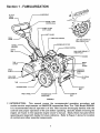
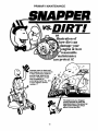
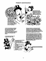
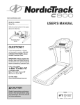
Safety Instructions
& Operator's Manual for
INTERMEDIATE
REAR TINE TILLER
SERIES 3
MODEL
IR5003B
NIR5OO3B
MODEL
NUMBER
EXPLANATION
I I I I
MODEL DESIGNATION
ENGINE MODEL
SERIES DESIGNATION
ENGINE HP
REAR TINE MODEL
I-Intermediate
Size Model
R - Rear Tine Type Model
I 50 -5
I
HP Engine (Horse Power)
I 3-Series
I
Designation
B - Briggs Engine
Thank you for buying a SNAPPER product! Your Tiller was designed and built to provide long and satisfactory service.
Study this manual carefully before operating the Tiller and pay particular attention to the Important Safety Instructions
found herein. Keep in mind that a Tiller, like any other mechanical device, can be potentially dangerous if used
improperly. Following the instructions in this and the engine manual will help you continue to enjoy the trouble-free
operation expected of a SNAPPER.
SNAPPER, McDonough,
GA., 30253
U.S.A.
COPYRIGHT
© 1999
SNAPPER INC.
ALL RIGHTS RESERVED
MANUAL No. 2-8701 (REV. 2, 5/18/99)
IMPORTANT
SAFETY INSTRUCTIONS
WARNING: This powerful machine is capable of amputating hands and feet and can throw objects that can
cause injury and damage! Failure to comply with the following instructions may result in serious injury to the
operator or other persons. The owner of the tiller must understand these instructions and, furthermore,
must
allow only persons who understand these instructions to operate tiller. Each person operating the tiller must be
of sound mind and body and must not be under the influence of any substance, which might impair vision,
dexterity, or judgment. If you have any questions pertaining to your tiller which your dealer cannot answer to
your satisfaction, call or write the Customer Service Department at SNAPPER, McDonough, Georgia, 30253.
Phone: (1-800-935-2967).
PROTECTION
1.
2.
3.
4.
5.
FOR CHILDREN
DO NOT allow children in area when tiller is
being operated.
DO NOT allow pre-teenage children to operate
tiller.
Allow only responsible teenagers or adults with
mature judgment to operate tiller and only under
close supervision.
Keep the area clear of all persons, particularly
small children, and pets.
Know how to STOP the tiller and disengage the
controls quickly.
PREPARATION
1.
2.
3.
4.
5.
6.
Read this manual, get to know where all controls
are located and practice how to use them before
starting for the first time, and at the beginning of
each season. Be thoroughly familiar with the
controls and proper use of the equipment. Pay
attention to Warning and Instructional Decals on
engine and tiller.
Never operate tiller without proper guards, drag
shield, plates, safety switches, or other safety
protective
devices
in place
and
properly
connected. Inspect to determine that these safety
devices are installed properly, are in good repair,
and operate properly.
If the condition
or
operation of these devices are questionable, they
must be repaired or replaced before using the
tiller.
Thoroughly inspect the area where the tiller is to
be used and remove all stones, sticks, wire,
bones and other foreign objects. Also, note the
location of holes, stumps, and other possible
hazards.
DO NOT operate tiller when barefoot or wearing
open sandals. Always wear long pants and
substantial footwear with good traction.
Fill fuel tank outdoors and replace fuel cap
before starting
engine.
Use approved
fuel
container.
DO NOT smoke near open fuel
container. DO NOT fill fuel tank indoors or when
engine is running. Allow engine to cool for at
least ten minutes before refilling. Wipe off any
spilled fuel before starting engine. DO NOT run
engine indoors.
Make sure that clutch is disengaged
and
transmission is in neutral (if so equipped) before
starting engine.
OPERATIONAL
PRECAUTIONS
1.
DO NOT change engine governor settings or
over speed engine.
2. DO NOT put hands or feet near or under rotating
parts.
3. Exercise CAUTION when crossing gravel drives,
walks, or roads, and under any conditions when
tiller is transported. Look behind and use care
when backing.
4. After striking a foreign object or if tiller vibrates
abnormally, STOP the engine, disconnect and
secure spark plug wire away from plug. Inspect
the tiller for any damage and repair the damage.
5. When leaving tiller unattended, disengage clutch,
shift transmission to neutral (if so equipped) and
stop the engine.
6. Before removing
debris or cleaning tines,
repairing or inspecting make certain engine,
tines and all moving parts have STOPPED.
Disconnect and secure spark plug wire away
from plug to prevent accidental starting.
7. Exercise CAUTION when changing directions
while operating tiller. DO NOT till in areas where
stability or traction is in doubt.
8. DO NOT overload the machine capacity by
attempting to till too deep at too fast a rate.
9. Be extra careful when tilling hard ground. Use
less tine engagement to maintain control of tiller.
10. Till only in daylight or in good artificial light.
11. Never operate tiller in wet areas. Always be sure
of your footing; keep a firm hold on the handle.
12. Do not operate on slopes
MAINTENANCE
1.
2.
3.
4.
5.
AND STORAGE
Keep all nuts, bolts, and screws tight and be sure
tiller is in safe operating condition.
Never store tiller with fuel in tank inside of a
building where fumes may reach an open flame
or spark. Allow engine to cool before storing in
any enclosure.
To reduce fire hazard, keep engine free of spilled
fuel, debris and excessive grease.
Have your tiller inspected and serviced each year
by an authorized Snapper dealer. Determine if
any additional devices are available which might
upgrade the safety of your tiller.
Factory specified Snapper replacement
parts
must be used to assure adequate protection
against injury.
TABLE OF CONTENTS
IMPORTANT
TABLE
SAFETY
INSTRUCTIONS
OF CONTENTS
SECTION
...................................................
............................................................................
1 - FAMILIARIZATION
2
3
..............................................................
4
SECTION 2 - OPERATING INSTRUCTIONS
.........................................
Transmission
Positions ...............................................................
Pre-Start Checklist ........................................................................
5-7
5
5
Starting & Stopping ...................................................................
Handlebar Adjustment ..................................................................
Transporting ..................................................................................
Tilling Procedure ........................................................................
SECTION 3 - ADJUSTMENTS
& REPAIR ...........................................
Service Parts & Assistance ..........................................................
Standing Tiller On End .................................................................
Tiller Lubrication ...........................................................................
Tiller Tines .....................................................................................
Belt Adjustment & Replacement ..................................................
Off Season Storage .....................................................................
WARRANTY
PRIMARY
............................................................................................
MAINTENANCE
................................................................
NOTES ...............................................................................................
5-6
6
6
6-7
8-10
8
8
8
9
9
10
11
12-15
16-17
Section 1 - FAMILIARIZATION
CLUTCH
CABLE
COVER
WHEEL&TINE
CONTROL BAIL
SHIFT LEVER
DASH
PANEL
THROTTLE
CONTROL
LEFT SIDE SHOWN TO
VIEW CHECK PLUG
HANDLE
BRACKET
CONTROL
AIR FILTER
DEPTH
BAR
EASE
_
MAIN CASE GR
CHECK PLUG
ENGINE
TINE
COVER
DRIVE
BELT
GUARD
/
DRAG
SHIELD
ENGINE OIL
CHECK/FILL
PLUG
MAIN CASE
FILL PLUG
OIL DRAIN
PLUG
TINE
STARTER ROPE--
TIRE & WHEEL
WEIGHT
BOX
TRANSMISSION
CHAIN CASE
STAND-UP
BAR
FIGURE 1
1.1 INTRODUCTION:
This manual covers the recommended
operating
procedure
and
routine service requirements
on SNAPPER Intermediate
Rear Tine Tiller Model IR5003B.
It is recommended
that all operator's of this Tiller become thoroughly familiar with the
controls and proper operation of the unit before operating.
Specific details involving the
engine are found in the separate engine owner's manual.
Study these manuals before
operating and keep both handy for future reference.
Refer to Figure 1 above for location
of controls and other essential components.
Section 2 - OPERATING
2.1
INSTRUCTIONS
BEFORE OPERATING:
Be thoroughly familiar with the operation of ALL controls
and how to use them BEFORE operating your Tiller.
Transmission shifting is done by shifting the WHEEL
and TINE SHIFT LEVER into the desired position.
Refer to Figure 3.
FIGURE 2
When activated, the tines rotate in a rearward (Reverse)
direction ONLY. With the engine running, shift into the desired
transmission position and pull the WHEEL and TINE
CONTROL BAIL against the handle bar to start wheel or
wheel and tine rotation.
2.1.1 TRANSMISSION POSITIONS
The Tiller has four transmission positions:
NOTE: The four different transmission positions shown on
the cover are close to actual positions of shift lever but are
not exact. Use positions as a reference.
1. FWD & TIL - (FORWARD and TILL) (Wheels and
Tines
are engaged).
2. FWD - (FORWARD) (Only the Wheels are engaged).
3. NEU - (NEUTRAL) (Wheels and Tines are disengaged).
4. REV - (REVERSE) (Rearward Wheel rotation).
Wheel or wheel and tine rotation is STOPPED by releasing
the WHEEL and TINE CONTROL BAIL. When the bail is
released, rotation should STOP even with the WHEEL and
TINE SHIFT LEVER in an engaged position. See Figures 3
and 4.
2.2
PRE-START CHECKLIST
Make the following checks and perform services as
required before each start up. NOTE: Before checking
oil level place 2x4 piece of wood under both wheels to
level engine.
2.2.1 CHECK ENGINE OIL and bring level up to full.
(Refer to engine manual for oil specifications).
2.2.2 CHECK AIR CLEANER and service according to
instructions in engine manual.
2.2.3 CHECK EXTERNAL SURFACES and remove dirt
and dust accumulation and clean tines as needed.
2.2.4 CHECK GUARDS to make sure all are in proper
position and securely tightened.
2.2.5 FILL FUEL TANK where fumes will be safely
dissipated. Refer to engine manual for fuel specifications.
2.3
\
& TINE
SHIFT LEVER
NEUTRAL
POSITION
FIGURE 3
STARTING - STOPPING
Know beforehand how to stop the tines, wheel drive and
engine in preparation for possible emergencies. The
engine is stopped by pulling the engine. THROTTLE
CONTROL to the rear to STOP. See Figure 2.
TO STOP WHEEL
& TINE DRIVE
RELEASE
WHEEL & TINE
CONTROL B_L
STOP
\
FIGURE 4
THROTTLE
CONTROL
Section 2 - OPERATING
2.4
INSTRUCTIONS
ENGINE STARTING PROCEDURE
Step 1: Place the WHEEL and TINE SHIFT LEVER in
the NEUTRAL position and make sure the WHEEL and
TINE CONTROL BAIL is in the releasedposition.
Step 2: For cold starts, move the CHOKE CONTROL
on the engine forward into CHOKE position.
See Figure 5.
LOW
MEDIUM
REMOVE
SCREW TO
ADJUST
HANDLEBAR
HANDLE
BRACKET
PUSH
FORWARD
TO CHOKE
FIGURE 6
\
LEVER
FIGURE 5
Step 3: Move THROTTLE
position.
CONTROL
to RUN
Step 4: Move to the right side of Tiller and place
your foot on top of the right wheel (See starting
procedure decal located on top of the tine cover),
hold handle bar, then pull the ROPE STARTER
HANDLE in smooth, steady motion until the engine
starts. To prolong the life of the rope, guide the
handle back to the engine rather than allowing it to
snap back.
2.6 TRANSPORTING
2.6.1
FORWARD/REVERSE: To transport the Tiller to
a new tilling site using its own power, raise the tines to clear
lawn and paved surfaces to prevent gouging. Release the
WHEEL and TINE CONTROL BAIL and lift the rear of the
Tiller to take the weight off the DEPTH BAR (see Figure 7),
then push the DEPTH BAR downward into notch setting
that allows the tines to clear the ground surface. Place the
WHEEL and TINE SHIFT LEVER in FWD or REV. Pull the
WHEEL and TINE CONTROL BAIL back against the
handlebar to engage the wheel drive and transport the unit.
2.6.2
To transport the Tiller to a new tilling site by
pushing it, place the WHEEL and TINE SHIFT LEVER in
the NEUTRAL position, and with the bail released, push the
unit with the handle bar. The Tiller may be pushed with the
engine running or shut off.
ADJUST
UP
OR
DOWN TO
DESIRED
TILLING DEPTH
mr
II
_1_
\
r" J!
L
_
/?/
/
/
Step 5: Allow a brief warm-up period, then move
the CHOKE
CONTROL
rearward
and the
THROTTLE
CONTROL
to the desired speed
setting. Refer to the tilling procedure column on
this page.
Step 6: To STOP the engine, pull the THROTTLE
CONTROL on engine rearward into STOP position.
2.5
HANDLE
Remove
bracket.
required.
BAR ADJUSTMENT
retaining screw and nut from handle bar
Adjust handle bar "UP" or "DOWN" as
Reinstall screw and nut. See Figure 6.
DEPTH
BAR
DEEP
T,LL \
PULL SPRING
BACK TO
RELEASE
TENSION
FIGURE 7
2.7 TILLING PROCEDURE
Tines are engaged ONLY when the WHEEL and TINE
SHIFT LEVER is in the FWD & TIL position and the
WHEEL and TINE CONTROL BAIL is held against the
handle bar.
1. Set HANDLE BAR in desired position before
beginning operation.
2. Set DEPTH BAR in highest position for deepest tilling
depth or in intermediate notches for lesser depth.
See Figure 7.
Section 2 - OPERATING INSTRUCTIONS
2.7
TILLING PROCEDURE
(Continued from previous page)
3. Set SPEED
by moving
the THROTTLE
CONTROL to desired setting.
4. To start TILLING action, move the WHEEL and
TINE SHIFT LEVER to the FWD & TIL position
(See Figure 8). Step behind the Tiller and raise
the WHEEL and TINE CONTROL BAIL up
against the handlebar to start forward movement
of the Tiller and rearward rotation of the tines.
MOVE SHIFT LEVER
TO FWD
POSITION
f
FWD & TIL
POSITION
\
FIGURE 8
2.7.1 TILLING HINTS: Let the Tiller do the work!
DO NOT try to hold it back. If forward motion ceases
while tilling deep, lift up slightly on the handle bar to
resume moving forward.
2.7.2 ROUGH TERRAIN HINT: If tilling over very
rough, uneven ground, till at a shallow depth setting
on the first path to smooth the surface.
On
especially rough terrain, the Tiller could hang up
underneath with the wheels spinning freely. Under
this condition, lift the handle bar, then turn the tiller
diagonally uphill to regain traction.
Section 3 -ADJUSTMENTS
& REPAIR
3.1
SERVICE PARTS & ASSISTANCE
To retain the original quality of your Tiller, use only
genuine SNAPPER replacement parts. Specify the
model and serial number as found on the
nameplate of your Tiller when contacting your
SNAPPER Dealer for parts or service assistance.
3.2
STANDING THE TILLER ON END
LLW
WARNING
AYS STOP the engine and DISCONNECT the spark
plug wire BEFORE standing the TILLER on end to
prevent accidental starting! NEVER stand Tiller on end
with the engine running!
WARNING
If the fuel tank is over half full when the Tiller is placed on
end, gasoline may leak from the carburetor vent hole and
drip down the outside surface of the engine creating a
_otential FIRE HAZARD! Gasoline may also leak unnoticed
into the engine cylinder and wash away lubricating oil
causing engine damage. Take all necessary precautions to
_revent fuel leakage BEFORE standing the Tiller on end.
Any draining of fuel must be done outside with the engine
cool and away from ignition sources. If the Tiller is stored on
end for any length of time, check it frequently for signs of fuel
and/or oil leakage.
3.3
TILLER LUBRICATION
CHAIN CASE: Check the level of the grease in the
chain case at the beginning of each tilling season.
Remove clevis pin and cotter pin that secures left
hand tire/wheel to axle. Remove wheel. Check
grease level by removing the plastic plug located
beside the axle shaft on the lower left hand side.
See Figures 9A. The level should be up to the edge
of the opening. To add grease, remove the filler
plug located just forward of the pulley shaft on the
right hand side. See Figure 10. Add Snapper Part
No. 2-9577 Benalene 900 grease (4 oz. Bottle) as
needed to bring level up to bottom edge of the
check plug opening. The total capacity of the case
is about 48 ounces. DO NOT exceed this amount.
Reinstall check plugs after checking. NOTE: Also
available Snapper Part No. 2-9296 Benalene 900
grease (32 oz. Bottle).
,-
,, PJ
..
WARNING
NEVER stand Tiller on end with
engine running!
"1 1 ,L
_/--'TIRE/WHEEL
3.2.1 ENGINE SERVICE: Refer to the engine
owner's manual for details. Engine oil is drained by
removing front filler plug and standing Tiller on end.
See Figure 9.
LEVEL
3.2.2 SERVICE NOTE:
operates under extremely
the air cleaner, engine oil
serviced as specified in
frequent intervals. The
serviced as follows:
Since a Tiller normally
dusty or dirty conditions,
and cooling fins must be
the engine manual at
Tiller itself should be
FIGURE 9A
\
OIL
STAND
TILLER
ON END
TO DRAIN
ENGINE
OIL
CHAIN
_,_,_
CASE
_
,
WHEEL
FIGURE 10
FIGURE 9
MAINCASE
Section 3 -ADJUSTMENTS
& REPAIR
3.4 TILLER TINES
Your Snapper Tiller has right hand and left hand
tines. Replace both tines if blades become bent or
are badly worn or otherwise damaged. Use correct
Snapper replacement tines. The tines are secured
to the tine shaft with a shear bolt, Part No. 2-8725
and Lock Nut Part No. 9-0222 on each side. NOTE:
Two extra nuts and two bolts come with tiller. Keep
spares on hand in case a bolt shears off or
becomes lost while tilling. See Figure 11. DO NOT
over tighten these shear bolts as this will cause
premature failure. (Recommended torque is 5 to 8
foot pounds maximum). NOTE: Failure to use the
correct shear bolts could result in serious damage
to your Tiller. Use only the genuine Snapper
replacement bolts and lock nuts specified above.
These bolts are designed to shear at a specific
stress to prevent damage. DO NOT use substitutes!
SHEAR
BOLT
(TORQUE TO
8 FT. LBS.}
\
i
1/4" TO
BELT
GUIDE
IDLER
PULLEY
IDLER
FIGURE 12
_,f..,
,._._
"f._
/
/F'_"
/'/"
T,
NE
ASSEMBLY
_M--_;T._
....
,l_r
_
I!
I_
_
I CLUTCH
I- MOVE NUTS
"TOWARD END
OF CABLE
FOR MORE
TENSION
FIGURE 13
r,/" ,;k
/
FIGURE 11
3.5
"
/
-..-....-----41_
/HANDLEBAR
DASH PANEL
\
_.
TINE
COVER
/
-S_
BELT ADJUSTMENT - REPLACEMENT
BELT TENSION ADJUSTMENT: Remove the cotter
pin that secures clevis pin to left wheel hub. Remove
clevis pin from left wheel hub and slide wheel out on
axle about 1". Remove belt guard. Measure the
length idler pulley spring at the end of the control
cable in a relaxed position. Then move wheel and
tine control bail up to the handle bar and measure
the extended length of the spring. When properly
adjusted, the spring will extend 1/4" to 1/2". See
Figure 12. To adjust, loosen and reposition the two
jam nuts on the threaded end of cable located on the
dash panel. Move jam nuts toward the end of
threaded end of cable for more tension. Move jam
nuts in a direction away from the end of threaded
end of cable for less tension. See Figure 13. After
adjustment, retighten both jam nuts against dash
panel. Reinstall belt guard. Slide wheel back into
operating position and reinstall clevis pin and secure
with hair pin.
3.5.1 TENSION TEST: Start the engine with tiller in
neutral. Shift transmission into FWD & TILL and pull the
wheel and tine control bail up against the handle bar.
Tines and wheels will start to rotate. Release control bail.
Tines and wheels should stop rotating immediately. If
rotation continues after release of control bail then clutch
spring tension is to great and will have to be readjusted
as described in BELT TENSION ADJUSTMENT Section.
3.5.2 BELT REPLACEMENT: Pull the clevis pin from
the left wheel and slide the wheel out 1", remove belt
guard and then the old belt. NOTE: Replacement belt
must go over the top of the idler and be within the belt
guide as shown in Figure 14. Check belt tension as
described in BELT TENSION ADJUSTMENT Section.
Reinstall guard, push left wheel back into position and
secure with clevis pin and insert and secure cotter pin.
BELT
GUIDE
SHIFT
LEVER
DRIVE
DRIVEN
PULLEY
BELT
TOP OF IDLER
Section 3 -ADJUSTMENTS
& REPAIR
3.6 OFF SEASON STORAGE
Thoroughly clean all external surfaces and tines before
storing the Tiller. The Tiller may be stored on end,
however, the following steps must be taken:
4. At the start of the new season, replenish engine
crank-case oil and add gasoline to the fuel tank after
returning the Tiller to its wheels.
5. Before starting, move the ENGINE CONTROL to
STOP and pull rope starter slowly several times. If
excessive resistance is felt, remove the spark plug
and pull rope starter rapidly to spin the engine and
clear oil from the cylinder. Clean and reinstall spark
plug before attempting to start the engine.
1. Drain gasoline from fuel system and drain the engine
crankcase oil (refer to engine manual for details).
2. After standing the Tiller on end, check the plugs in the
chain case for leakage. After extended period, some
grease may seep thru upper bearing races.
3. Remove both wheels and grease wheel shafts.
Reinstall wheels. Remove both tines and grease tine
shafts. Reinstall tines. Grease these shafts when tiller
is stored for long periods of time to prevent rust
buildup. Rust buildup will cause wheels and tines
difficult to remove.
10
3 YEAR
LIMITED
WARRANTY
For three (3) years from purchase date for the original purchaser's residential, non-commercial use, SNAPPER, through
any authorized SNAPPER dealer will replace, free of charge (except for taxes where applicable), any part or parts found
upon examination by the factory at McDonough, Georgia, to be defective in material or workmanship or both.
For ninety (90) days from purchase date for the original purchaser's commercial, rental, or other non-residential use,
SNAPPER, through any authorized SNAPPER dealer will replace, free of charge, any part or parts found upon
examination by the factory at McDonough, Georgia, to be defective in material or workmanship or both.
All transportation costs incurred by the purchaser in submitting
replacement under this warranty must be paid by the purchaser.
material to an authorized
SNAPPER
dealer for
This warranty does not apply to engines and their components, and batteries, as these items are warranted separately.
This warranty does not apply to parts that have been damaged by accident, alteration, abuse, improper lubrication,
normal wear, or other cause beyond the control of SNAPPER. This warranty does not cover any machine or component
part that has been altered or modified changing safety, performance, or durability.
Batteries have a one (1) year prorated warranty period with free replacement if required during the first ninety (90) days
from the original purchase date. SNAPPER will not be responsible for any installation cost incurred. The battery warranty
only covers original equipment batteries and does not cover damage to the battery or machine caused by neglect or
abuse, destruction by fire, explosion, freezing, overcharging, improper maintenance, or use of improper electrolyte.
There is no other express warranty.
DISCLAIMER OF WARRANTY
Implied warranties, including those of merchantability and fitness for a particular purpose, are limited to three
(3) years from purchase date for the original purchaser's residential or other non-commercial use, and ninety
(90) days from purchase for the original purchaser's commercial, rental or other non-residential use, and to the
extent permitted by law, any and all implied warranties are excluded. This is the exclusive remedy. Liabilities for
consequential damages, under any and all warranties are excluded.
Some states do not allow limitations on how long an implied warranty lasts, or do not allow the exclusion or
limitation of incidental or consequential damages, so the above limitation or exclusion may not apply to you.
This warranty gives you specific legal rights, and you may also have other rights which vary from state to state.
WARNING: THE USE OF REPLACEMENT PARTS OTHER THAN GENUINE SNAPPER PARTS MAY IMPAIR THE
SAFETY OF SNAPPER PRODUCTS
AND WILL VOID ANY LIABILITY AND WARRANTY
BY SNAPPER
ASSOCIATED WITH THE USE OF SUCH PARTS.
IMPORTANT: Please fill out the attached SNAPPER Product Registration Card immediately and mail to:
Snapper's Product Registration Center, P.O. Box 1379, McDonough, Georgia 30253
11
PRIMARY MAINTENANCE
®
vs.DIRT I
an
illustration of
how dirt can
ge your
_engine & how
reasonable
maintenance
can protect it!
Snapper uses the best available engines and components
In their products in order to
provide long, satisfactory
service. However, proper
care is essential In
prolonging engine life. Dirt
Is your engine's enemy
number 11
The engine on your Snapper
product spends Its entire life
operating close to the ground at
high speed creating a virtual
storm of dust and dirtl
12
PRIMARY MAINTENANCE
I(nowing that dirt will
quickly ruin an engine,
manufacturers equip their
engines with extremely
efficient air cleaners to
filter out the harmful dirt.
gulp about 12,000
gallons of air for
used. Because of
its working environment, the air available
to your Snapper engine Is "
heavily saturated with airborne dirt particles.
As the dirt particles are stopped,
they build up and begin to clog
the outside of the filter. This
reduces the amount of air
available to the engine and causes
an over-rich fuel mixture which results In the following adverse
effects:
Damage caused by a poorly serviced air
cleaner is not covered under the engine
warranties. So, save yourself unnecessary
expenses and undue aggravation by keeping
the air cleaner properly serviced at the Intervals
specified In the engine owner's manual.
An Improperly serviced, dirt
clogged air cleaner will:
1.
2.
3.
4.
Increase fuel consumption
cause power loss
result In hard starting
create smoke from unburned
fuel
5.
produce carbon build-up ;
Internally
foul spark plug electrodes
score cylinder walls
burn valves
wear out the engine prematurely
COST YOU MONEY!
6.
7.
8.
9.
10.
13
It doesn't take long to service an air cleaner.
Follow the specific instructions In the engine
owner's manual for the type filter used. Prevent dirt from falling Into the carburetor Intake
when ssrvicing your air cleaner• Make sure
components are Installed In correct sequence
after ssrvicing to prevent unfiltered air from
entering the engine. Some servicing hints on
several common types are:
PRIMARY MAINTENANCE
Air is also needed to keep
your engine cool. Dirt, dust
& debris build up to restrict
and clog cooling air Intake
screens and fins. Clean
screens and fins at frequent
Intervals. The engine blower
housing and shrouds should
be removed at least once
each season or more often
under dry, dusty conditions
for a thorough cleaning of
fins.
Generally, wash foam-type filters
In a dishwashlng detergent and
water solution. Rinse and wring
dry, then saturate with oil and
squeeze out excess. Failure to
re-oil this type filter will ruin the
engine.
Failure to keep external
surfaces clean not only
presents fire hazards, but
causes overheating and
resulting engine damages
such as:
1.
2.
° o. 3.
.,,_.
4.
5.
6.
Clean paper elements by tapping
lightly. Blowing with air will
rupture paper elements.
Use a flashlight to detect clogged
or torn paper elements - replace If
damaged in any way.
distorted valve guides
sticking valves
scuffed, scored
walls
overspeedlng
loss of power
complete failure of
engine.
Dirt can also be Introduced
Into an engine In dirty fuel
from a contaminated
container. Always use clean
fresh fuel from a clean
container to guard against
dirt, sludge and water
contamination.
Be aware that fuel breaks
down in storage and forms
gummy compounds which
will block carburetor passages. Never use fuel more
than 3 months old. Drain
tank then run the engine out
of fuel before storing during
the off-season.
An engine must also have proper lubrication.
All englnes use some oli. On 4-cycle englnes,
CHECK OIL LEVEL BEFORE EACH START-UP.
Wlpe area clean around the oli check plug or
dlpstlck opening to keep dlrt from falllng Into
the englne when checklng the oli. Always
check wlth the machlne on a level surface.
On englnes wlth dlpstlck, keep the level up to,
but not over, the FULL mark. When addlng oli,
allow tlme for all of the oli to flow down the fill
tube to prevent a false full readlng when the
level could actually be low and result In englne
damage.
14
PRIMARY MAINTENANCE
On 2-cycle engines, lubrication must be
provided by an exact mixture of gasoline
and 2-cycle air-cooled engine oil. A 2-cycle
engine that Is mistakenly run on straight
gasoline will be ruined in less than 5
mlnutesl If you keep straight gasoline in
addition to pre-mixed 2-cycle engine fuel,
be sure the containers are clearly marked
to avoid mix-up.
Snapper 2-cycle engines require a 32 to 1
mixture of gasoline and BIA certified TC-W
oll such as Snapper's 2-cycle engine oil.
Many of the 2-cycle engine oils on the
market today make fantastic claims, but for
the best performance and long engine life,
always use Snapper 2-cycle oil. Pre-mlx
the fuel and always shake the container
before filling the tank.
On 4-cyle engines with an oll level plug,
don't be fooled into thinking the engine has
sufficient lubricating oil if you can see "some"
oil in the opening - the level should always be
brought up to the point of
at the
top of the fill hole.
Change oil at regular Intervals using a a high
quality oil such as Snapper's small engine
formulated 4-cycle engine oil Refer to the
engine owner's manual for oll details.
STARTING
CHECK
1.
Engine 011
•
•
2.
Air Cleaner
3.
Fuel Tank
4.
5.
Choke
Primer (on
some engines)
Safety Interlock Switches
SwHch &
Blade Control
•
•
•
•
•
•
•
6.
7.
8.
Spark plug
g.
10.
Throttle
control
Blade
11.
Muffler
•
•
•
•
•
•
•
•
•
•
•
•
LIST
Read and follow all safety
Instructions in safety book- I
lets and manuals.
,]
To full level (4-cycle)
Properly mixed with gas
(2 cycle)
Clean and properly serviced
Full fresh clean gasoline
Fuel valve open
Cap vent open
Inline filter clean
Operating properly
Used properly
Keep in mind that dirt Is your engine's enemy
#1 both Internally and externallyl Internally,
dirt will quickly ruin an engine and externally
It will cause overheating and resulting internal
damages. Damage caused by Improper lubrlpoor air cleaner service or overheating
due to dirt cannot be covered under warranty.
It only takes a few moments to service the
engine (and equipment) on a routine basle
but the rewards will be a quick starting, responsive engine that will provide long
satisfactory service with minimum maintenance
cOSL The prestart checklist In the next column
and Instructions In your Snapper Operator's
Manual are designated to help you keep your
Snapper In top operating condition with
minimum effortl
In proper position
All wires properly connected
Switch On
Blade control properly
positioned on walk mower
Wlra connected
Good connection
Start position
Properly Installed and
torqued
Sharpened
Good condlUon
Not clogged
Grass & leaves cleaned away
I
15
II
I
SERVICE NOTES
16
SERVICE NOTES
17
Safety Instructions
& Operator's Manual for
®
INTERMEDIATE
REAR TINE TILLER
SERIES 3
MODELS IR5003B & NIR5OO3B
I AWARNING:
I
The
engine exhaust
this birth
product
contains
chemicals
known
to the State I
of California
to cause from
cancer,
defects
or other
reproductive
harm.
SNAPPER,
COPYRIGHT
McDonough,
GA., 30253
U.S.A.
© 1999
SNAPPER INC.
ALL RIGHTS RESERVED
MANUAL No. 2-8701 (REV. 2, 5/18/99)
18