1
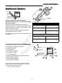
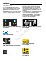
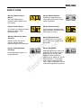
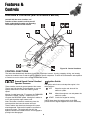
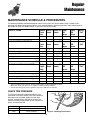
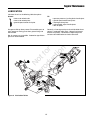
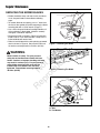
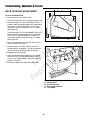
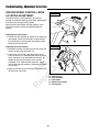
N
ep o
ro t fo
du r
ct
io
n
OPERATOR’S
MANUAL
R
Hydro Cut Series
13HP Walk-Behind Mower
Mfg. No.
1694562
5901182
5900846
Description
Hydro Cut 1332, 13HP 32” Cut Walk-Behind Mower (CE)
HC32KAV13ECE, 13HP 32” Cut Walk-Behind Mower (CE)(2006)
HC32RDKAV13ECE, 13hp 32” Rear Discharge Cut Walk Behind Mower (CE)
Form No. 1726645
Revision J
Rev. Date 03/2009
TP 100-4024-J-HC-S
N
ep o
ro t fo
du r
ct
io
n
R
Table of Contents
Safety Rules & Information ................................2
Identification Numbers .......................................5
Safety Decals & Icons.........................................6
Features & Controls ............................................8
Regular Maintenance ........................................15
Maintenance Schedule .........................................15
Checking Tire Pressure.........................................15
Checking/Adding Fuel...........................................16
Fuel Filter ..............................................................16
Oil & Filter Change ...............................................16
Check / Change Air Filter......................................16
Replace Spark Plug ..............................................16
Transmission Maintenance ...................................16
Lubrication ............................................................17
Servicing the Mower Blades .................................18
Control Functions....................................................8
Safety Interlock System ..........................................9
Operation ...........................................................12
General Operating Safety .....................................12
Checks Before Starting .........................................12
Starting the Engine ...............................................12
Driving the Mower .................................................13
Operating On A Slope...........................................13
Stopping the Mower ..............................................13
Mowing..................................................................13
Pushing the Mower by Hand.................................13
Storage..................................................................14
Starting After Long Term Storage .........................14
Troubleshooting, Adjustments & Service .......19
N
ep o
ro t fo
du r
ct
io
n
Troubleshooting the Mower ...................................19
Troubleshooting the Mower Deck..........................20
Cutting Height Adjustment ....................................21
Deck Leveling Adjustment.....................................22
Belt Removal and Replacement ...........................23
Ground Speed Control Lever Adjustment .............24
PTO Clutch Adjustment ........................................25
NOTE: In this manual, “left” and “right” are referred to as
seen from the operating position.
WARNING
WARNING
You must read, understand and comply with all
safety and operating instructions in this manual
before attempting to set-up and operate your
machine.
R
Engine exhaust from this product contains
chemicals known, in certain quantities, to cause
cancer, birth defects, or other reproductive harm.
Failure to comply with all safety and operating
instructions can result in loss of machine control,
serious personal injury to you and / or
bystanders, and risk of equipment and property
damage. The triangle in the text signifies
important cautions or warnings which must be
followed.
1
Safety Rules & Information
Read these safety rules and follow them closely. Failure to obey these rules could result in loss of control
of unit, severe personal injury or death to you, or bystanders, or damage to property or equipment.
This mowing deck is capable of amputating hands and feet and throwing objects.
The triangle
in text signifies important cautions or warnings which must be followed.
GENERAL OPERATION
trouble.
17. Always wear eye protection when operating machine.
18. See manufacturer’s instructions for proper operation
and installation of accessories. Only use accessories
approved by the manufacturer.
19 Watch for traffic when operating near or crossing
roadways.
20. Use extra care when loading or unloading the unit
into a trailer or truck.
21. Always wear eye protection when operating this unit.
22. Data indicates that operators, age 60 years and
above, are involved in a large percentage of power
equipment-related injuries. These operators should
evaluate their ability to operate the equipment safely
enough to protect themselves and others from injury.
23. Keep in mind the operator is responsible for
accidents occurring to other people or property.
24. All drivers should seek and obtain professional and
practical instruction.
25. Before using, always visually check that the blades
and blade hardware are present, intact, and secure.
Replace worn or damaged parts.
26. Disengage attachments before: refueling, removing
an attachment, making adjustments (unless the
adjustment can be made from the operator’s
position).
27. Before leaving the operator’s position for any reason,
engage the parking brake (if equipped), disengage
the blades (PTO), stop the engine, and remove the
key.
28. To reduce fire hazard, keep the unit free of grass,
leaves, & excess oil. Do not stop or park over dry
leaves, grass, or combustible materials.
29. It is a violation of California Public Resource Code
Section 4442 to use or operate the engine on or near
any forest-covered, brush-covered, or grass-covered
land unless the exhaust system is equipped with a
spark arrester meeting any applicable local or state
laws. Other states or federal areas may have similar
laws.
R
N
ep o
ro t fo
du r
ct
io
n
1. Read, understand, and follow all instructions on the
machine and in the manual(s) before starting.
2. Do not put hands or feet near or under the machine.
Keep clear of the discharge opening at all times.
3. Only allow responsible adults, who are familiar with
the instructions, to operate this machine.
4. Clear the area of objects such as rocks,wire, toys,
etc., which could be thrown by the blade. Stay behind
the handle when the engine (motor) is running.
5. Be sure the area is clear of bystanders before
operating. Stop machine if anyone enters the area.
6. Do not operate machine barefooted or while wearing
sandals. Always wear substantial footwear.
7. Do not pull machine backward unless absolutely
necessary. Always look down and behind before and
while moving backward.
8. Never direct discharged material toward anyone.
Avoid discharging material against a wall or
obstruction. Material may ricochet back toward the
operator. Stop the blade when crossing gravel
surfaces.
9. Do not operate machine without the entire grass
catcher, discharge guard, rear guard, or other safety
protective devices in place and working.
10. Never leave a running machine unattended.
11. Stop the engine (motor) and wait until the blade
comes to a complete stop before cleaning the
machine, removing grass catcher, or unclogging the
discharge guard.
12. Operate machine only in daylight or good artificial
light.
13. Do not operate machine while under the influence of
alcohol or drugs.
14. Never operate mower in wet grass. Always be sure
of your footing; walk; never run.
15. Disengage the drive system, if so equipped, before
starting the engine (motor).
16. If the machine should start to vibrate abnormally,
stop the engine (motor) and check for the cause
immediately. Vibration is generally a warning of
TRANSPORTING AND STORAGE
4. Always follow the engine manual instructions for
storage preparations before storing the unit for both
short and long term periods.
5. Always follow the engine manual instructions for
proper start-up procedures when returning the unit to
service.
6. Never store the unit or fuel container inside where
there is an open flame or pilot light, such as in a
water heater. Allow unit to cool before storing.
1. When transporting the unit on an open trailer, make
sure it is facing forward, in the direction of travel. If
the unit is facing backwards, wind lift could damage
the unit.
2. Always observe safe refueling and fuel handling
practices when refueling the unit after transportation
or storage.
3. Never store the unit (with fuel) in an enclosed poorly
ventilated structure. Fuel vapors can travel to an
ignition source (such as a furnace, water heater, etc.)
and cause an explosion. Fuel vapor is also toxic to
humans and animals.
2
Safety Rules and Information
SLOPE OPERATION
WARNING
Slopes are a major factor related to loss-of-control and tipover accidents, which can result in severe injury or death.
Operation on all slopes requires extra caution. If you
cannot back up the slope or if you feel uneasy on it, do not
operate on it.
Control of a walk-behind or ride-on machine sliding on a
slope will not be regained by the application of the brake.
The main reasons for loss of control are: insufficient tire
grip on the ground, speed too fast, inadequate braking, the
type of machine is unsuitable for its task, lack of
awareness of the ground conditions, incorrect hitching and
load distribution.
1. Mow across the face of slopes; never up and down.
Exercise extreme caution when changing direction
on slopes.
2. Watch for holes, ruts, bumps, rocks, or other hidden
objects. Uneven terrain could cause a slip and fall
accident. Tall grass can hide obstacles.
3. Choose a slow speed so that you will not have to
stop or change speeds while on the slope.
4. Do not mow on wet grass or excessively steep
slopes. Poor footing could cause a slip and fall
accident.
5. Never mow down slopes.
6. Avoid starting, stopping, or turning on a slope. If
tires lose traction (i.e. machine stops forward motion
on a slope), disengage the blade(s) (PTO) and drive
slow off the slope.
7. Keep all movement on slopes slow and gradual. Do
not make sudden changes in speed or direction,
which could cause a slip and fall accident.
8. Use extra care while operating machines with grass
catchers or other attachments; they can affect the
stability of the unit. Do not use on steeps slopes.
9. Do not mow near drop-offs, ditches, or
embankments. You could lose your footing or
balance.
10. Do not use grass catchers on steep slopes.
11. Do not mow slopes you cannot back up them.
12. Remove obstacles such as rocks, tree limbs, etc.
13. Use slow speed. Tires may lose traction on slopes
even through the brakes are functioning properly.
Operating on steep slopes can cause sliding and
loss of steering, control and rollover.
Select slow ground speed before driving onto
slope. Use extra caution when operating on
slopes with rear-mounted grass catchers.
Mow across the face of slopes, not up and
down,use caution when changing directions and
DO NOT START OR STOP ON SLOPE.
CHILDREN
N
ep o
ro t fo
du r
ct
io
n
Tragic accidents can occur if the operator is not alert to the
presence of children. Children are often attracted to the
unit and the mowing activity. Never assume that children
will remain where you last saw them.
1. Keep children out of the mowing area and under the
watchful care of a responsible adult other than the
operator.
2. Be alert and turn mower off if a child enters the area.
3. Never allow children to operate the machine.
4. Use extra care when approaching blind corners,
shrubs, trees, or other objects that may block your
view of a child.
EMISSIONS
R
1. Engine exhaust from this product contains chemicals
known, in certain quantities, to cause cancer, birth
defects, or other reproductive harm.
2. Look for the relevant Emissions Durability Period and
Air Index information on the engine emissions label.
3
Safety Rules & Information
SERVICE AND MAINTENANCE
11. Do not remove the fuel filter when the engine is hot
as spilled gasoline may ignite. Do not spread fuel
line clamps further than necessary. Ensure clamps
grip hoses firmly over the filter after installation.
12. Do not use gasoline containing METHANOL, gasohol
containing more than 10% ETHANOL, gasoline
additives, or white gas because engine/fuel system
damage could result.
13. If the fuel tank must be drained, it should be drained
outdoors.
14. Replace faulty silencers/mufflers.
15. Maintain or replace safety and instruction labels as
necessary.
16. Use only factory authorized replacement parts when
making repairs.
17. Always comply with factory specifications on all
settings and adjustments.
18. Only authorized service locations should be utilized
for major service and repair requirements.
19. Never attempt to make major repairs on this unit
unless you have been properly trained. Improper
service procedures can result in hazardous
operation, equipment damage and voiding of
manufacturer’s warranty.
20. On multiple blade mowers, take care as rotating one
blade can cause other blades to rotate.
21. Do not change engine governor settings or overspeed the engine. Operating the engine at excessive
speed can increase the hazard of personal injury.
22. Disengage drive attachments, stop the engine,
remove the key, and disconnect the spark plug
wire(s) before: clearing attachment blockages and
chutes, performing service work, striking an object,
or if the unit vibrates abnormally. After striking an
object, inspect the machine for damage and make
repairs before restarting and operating the
equipment.
23. Never place hands near the moving parts, such as a
hydro pump cooling fan, when the tractor is running.
(Hydro pump cooling fans are typically located on top
of the transaxle).
24. Units with hydraulic pumps, hoses, or motors:
WARNING: Hydraulic fluid escaping under pressure
may have sufficient force to penetrate skin and cause
serious injury. If foreign fluid is injected into the skin
it must be surgically removed within a few hours by a
doctor familiar with this form of injury or gangrene
may result. Keep body and hands away from pin
holes or nozzles that eject hydraulic fluid under high
pressure. Use paper or cardboard, and not hands, to
search for leaks. Make sure all hydraulic fluid
connections are tight and all hydraulic hoses and
lines are in good condition before applying pressure
to the system. If leaks occur, have the unit serviced
immediately by your authorized dealer.
25. WARNING: Stored energy device. Improper release
of springs can result in serious personal injury.
Springs should be removed by an authorized
technician.
26. Models equipped with an engine radiator: WARNING:
Stored energy device. To prevent serious bodily
injury from hot coolant or steam blow-out, never
attempt to remove the radiator cap while the engine
is running. Stop the engine and wait until it is cool.
Even then, use extreme care when removing the
cap.
To avoid personal injury or property damage, use
extreme care in handling gasoline. Gasoline is
extremely flammable and the vapors are explosive.
N
ep o
ro t fo
du r
ct
io
n
Safe Handling of Gasoline
1. Extinguish all cigarettes, cigars, pipes, and other
sources of ignition.
2. Use only approved gasoline containers.
3. Never remove the gas cap or add fuel with the
engine running. Allow the engine to cool before
refueling.
4. Never fuel the machine indoors.
5. Never store the machine or fuel container where
there is an open flame, spark, or pilot light such as
near a water heater or other appliance.
6. Never fill containers inside a vehicle or on a truck
bed with a plastic bed liner. Always place containers
on the ground away from your vehicle before filling.
7. Remove gas-powered equipment from the truck or
trailer and refuel it on the ground. If this is not
possible, then refuel such equipment on a trailer with
a portable container, rather than from a gasoline
dispenser nozzle.
8. Keep nozzle in contact with the rim of the fuel tank or
container opening at all times until fueling is
complete. Do not use a nozzle lock-open device.
9. If fuel is spilled on clothing, change clothing
immediately.
10. Never over-fill the fuel tank. Replace gas cap and
tighten securely.
11. Use extra care in handling gasoline and other fuels.
They are flammable and vapors are explosive.
12. If fuel is spilled, do not attempt to start the engine
but move the machine away from the area of spillage
and avoid creating any source of ignition until fuel
vapors have dissipated.
13. Replace all fuel tank caps and fuel container caps
securely.
R
Service & Maintenance
1. Never run the unit in an enclosed area where carbon
monoxide fumes may collect.
2. Keep nuts and bolts, especially blade attachment
bolts, tight and keep equipment in good condition.
3. Never tamper with safety devices. Check their proper
operation regularly and make necessary repairs if
they are not functioning properly.
4. Keep unit free of grass, leaves, or other debris buildup. Clean up oil or fuel spillage. and remove any fuelsoaked debris. Allow machine to cool before
storage.
5. If you strike an object, stop and inspect the machine.
Repair, if necessary, before restarting.
6. Never make adjustments or repairs with the engine
running. Disconnect the spark plug wire(s) and
ground against the engine to prevent unintended
starting.
7. Check grass catcher components and the discharge
guard frequently and replace with manufacturer’s
recommended parts, when necessary.
8. Mower blades are sharp. Wrap the blade or wear
gloves, and use extra caution when servicing them.
9. Check brake operation frequently. Adjust and service
as required.
10. Maintain or replace safety and instructions labels, as
necessary.
4
Identification Numbers
Identification Numbers
Model xxxxxxx
SA
xxxxxxxxxxxxxxxxxxxx
M
Serial xxxxxxxxxx
XXX
PL
BRIGGS & STRATTON CORP.
POWER PRODUCTS GROUP, LLC
MILWAUKEE, WI 53201 USA
20xx
kg: xxx
kW: x.xx
xxxx max
E
ID Tag
When contacting your authorized dealer for
replacement parts, service, or information you MUST
have these numbers.
PRODUCT REFERENCE DATA
Record your model name/number, manufacturer’s
identification numbers, and engine serial numbers in the
space provided for easy access. These numbers can be
found in the locations shown.
Model Description Name/Number
NOTE: For location of engine identification numbers,
refer to the engine owner’s manual.
Unit MFG Number
Unit SERIAL Number
Dealer Name
Date Purchased
N
ep o
ro t fo
du r
ct
io
n
CE Models: Place the extra copy of the identification tag
in the manual.
ENGINE REFERENCE DATA
Engine Make
Engine Model
Engine Type/Spec
Engine Code/Serial Number
CE IDENTIFICATION TAG MARKINGS
Manufacturer’s Identification Number
Product Description
Serial Number
Manufacturer’s Address
CE Compliance Logo
Year of Manufacture
Maximum Engine Speed in Rotations per Minute
Power Rating in Kilowatts
Mass of Unit in Kilograms
Sound Power in Decibels *
B
Model xxxxxxx
C
J
xxxxxxxxxxxxxxxxxxxx
Serial xxxxxxxxxx
XXX
BRIGGS & STRATTON CORP.
POWER PRODUCTS GROUP, LLC
MILWAUKEE, WI 53201 USA
R
A.
B.
C.
D.
E.
F.
G.
H.
I.
J.
A
20xx
I
kg: xxx
kW: x.xx
xxxx max
D
H
E
This unit complies with European Harmonized Lawn Mower
Standard EN 836, European Machinery Directive 98/37/EC,
and European EMC Directive 89/336/EC
* Tested according to 2000/14/EC
5
F
G
Safety Decals
SAFETY DECALS
All DANGER, WARNING, CAUTION and instructional
messages on your unit should be carefully read and
obeyed. Personal bodily injury can result when these
instructions are not followed. The information is for your
safety and it is important! The safety decals below are
on your unit.
This unit has been designed and manufactured to
provide you with the safety and reliability you would
expect from an industry leader in outdoor power
equipment manufacturing.
Although reading this manual and the safety instructions
it contains will provide you with the necessary basic
knowledge to operate this equipment safely and
effectively, we have placed several safety labels on the
unit to remind you of this important information while you
are operating your unit.
If any of these decals are lost or damaged, replace them
at once. See your local dealer for replacements.
N
ep o
ro t fo
du r
ct
io
n
These labels are easily applied and will act as a
constant visual reminder to you, and others who may
use the equipment, to follow the safety instructions
necessary for safe, effective operation.
Decal - Main, Dashboard & Controls (Manual Start)
Part No. 5049317
49320
R
Decal - Transmission Release
Part No. 5049320
Decal - Main, Dashboard & Controls (Electric Start)
Part No. 5100507
Decal - Danger, Rotating Blades
Part No. 1720389
Decal - Cutting Height / Pulley Spacer Adjustment
Part No. 5049318
61217
Decal - Danger, Fire Hazard / Carbon
Monoxide Poisoning
Part No. 5061217
Decal - Cutting Height Adjustment
Part No. 5047778
6
Safety Icons
SAFETY ICONS
Danger: Machine Rollover.
Warning: Read Operator’s
Manual.
Operating on steep slopes can
cause sliding and loss of steering,
control and rollover.
Read and understand the
Operator’s Manual before using
this machine.
Danger: Thrown Objects.
Danger: Dismemberment.
This machine is capable of throwing
objects and debris. Keep
bystanders away.
This machine can amputate limbs.
Keep bystanders and children away
when engine is running.
Warning: Remove Key Before
Servicing.
Danger: Dismemberment.
This mower deck can amputate
limbs. Keep hands and feet away
from blades.
N
ep o
ro t fo
du r
ct
io
n
Remove the key and consult
technical literature before
performing repairs or maintenance.
Danger: Fire Hazard.
Danger: Carbon Monoxide
Poisoning.
Keep unit free of grass, leaves and
excess oil. Do not add fuel while
engine is hot or running. Stop
engine and allow to cool for 5
minutes prior to adding fuel. Do not
add fuel indoors, in an enclosed
trailer, garage or other enclosed
areas. Clean up spilled fuel. Do not
smoke while operating this machine.
R
Do not operate the engine in an
unventilated area.
7
Features &
Controls
FEATURES & CONTROLS (S/N: 2013136020 & BELOW)
N
ep o
ro t fo
du r
ct
io
n
Please take a moment and familiarize
yourself with the name, location, and
function of these controls so that you will
better understand the safety and operating
instructions provided in this manual.
Figure 1A. Control Locations
CONTROL FUNCTIONS
R
The information below briefly describes the function of individual controls. Starting, stopping, driving, and mowing
require the combined use of several controls applied in specific sequences. To learn what combination and sequence
of controls to use for various tasks see the OPERATION section.
Ground Speed Control Handles /
Operator Presence
Ignition Switch
The ignition switch starts and stops the engine, it has
three positions:
These handles control the ground speed of the mower.
The left and right handles are tied together so you can
operate either lever to control the mower’s ground
speed.
OFF
Stops the engine and shuts off the
electrical system.
RUN
Allows the engine to run and powers the
electrical system.
START Cranks the engine for starting.
NOTE: Never leave the ignition switch in the RUN
position with the engine stopped–this drains the battery.
Moving a handle forward to “F” increases the FORWARD
speed of the mower. Moving a handle back to “R”
increases the REVERSE speed. Moving the handles to
to “N” neutral position stops mower travel.
Note: The further a handle is moved away from the
neutral position the faster the mower will travel.
These handles also deactivate the engine kill system
when depressed. Release the handles to activate the
engine kill system. The engine will shut off if the
operator releases the handles with the PTO engaged or
parking brake disengaged.
8
Features & Controls
Throttle Control
Fuel Tank Cap
To remove cap, turn counterclockwise.
Pulling the round choke control knob (D) out fully chokes
the engine for cold starts. (A warm engine may not
require choking.) Moving the throttle control (C) fully
forward is FULL throttle position. Always operate the
unit at FULL throttle when mowing.
Transmission Release Valve
The transmission release valve deactivates the
transmissions so that the unit can be pushed by hand.
Engages the transmission; the mower will move
under its own power.
Choke
Close the choke for cold starting. Open the choke once
the engine starts. A warm engine may not require
choking. Pull the knob UP to close the choke. Push to
knob DOWN to open the choke.
Disengages the transmission; the mower can now
be pushed by hand.
See PUSHING THE MOWER BY HAND for operational
information.
PTO (Power Take Off) Switch
The PTO Switch engages and disengages the mower
blades.
SAFETY
INTERLOCK SYSTEM
N
ep o
ro t fo
du r
ct
io
n
To engage the mower blades, pull up on the switch. To
disengage the mower blades, push down on the switch.
When the PTO engagement lever or switch is in the
Engaged position, the Engine Kill system is activated.
Parking Brake
DISENGAGE
Releases the parking brake.
ENGAGE
Locks the parking brake.
This unit is equipped with safety interlock switches and
other safety devices. These safety systems are present
for your safety, do not attempt to bypass safety
switches, and never tamper with safety devices. Check
their operation regularly.
Operational SAFETY Checks
Your unit is equipped with an operator presence switch
safety system. Check the operator presence switch
operation every fall and spring with the following tests.
Pull the parking brake lever back to engage the parking
brake. Move the lever fully forward to disengage the
parking brake. NOTE: To start the unit the parking brake
must be engaged.
Test 1 — Engine WILL NOT start if:
• PTO switch is engaged.
Test 2 — Engine WILL start if:
R
• PTO switch is NOT engaged.
Test 3 — Engine should SHUT OFF if:
Cutting Height Adjust Handle
• Operator releases the operator presence / parking
brake handles with PTO engaged.
The cutting height adjust handle controls the mower
cutting height. To adjust the mower cutting height, turn
the crank handle clockwise to raise the cutting height.
Turn the crank handle counterclockwise to lower the
cutting height. Observe the cutting height indicator on
the left side of the mower deck.
Test 4 — Blade Brake Check
Mower blades and mower drive belt should come to a
complete stop within five seconds after electric PTO
switch is turned off (or operator releases operator
presence handles). If mower drive belt does not stop
within five seconds, see your dealer.
NOTE: Once the engine has stopped, PTO switch must
be turned off in order to start the engine.
WARNING
If the unit does not pass a safety test, do not
operate it. See your authorized dealer. Under no
circumstance should you attempt to defeat the
purpose of the safety interlock system.
9
Features & Controls
FEATURES & CONTROLS (S/N: 2013136021 & ABOVE)
N
ep o
ro t fo
du r
ct
io
n
Please take a moment and familiarize
yourself with the name, location, and
function of these controls so that you
will better understand the safety and
operating instructions provided in this
manual.
Figure 1B. Control Locations
CONTROL FUNCTIONS
The information below briefly describes the function of individual controls. Starting, stopping, driving, and
mowing require the combined use of several controls applied in specific sequences. To learn what combination
and sequence of controls to use for various tasks see the OPERATION section.
R
Ground Speed Control Handles
These handles control the ground speed of the mower.
The left and right handles are tied together so you can
operate either lever to control the mower’s ground
speed.
Ignition Switch
The ignition switch starts and stops the engine, it has
three positions:
OFF
Stops the engine and shuts off the
electrical system.
Moving a handle forward to “F” increases the FORWARD
RUN
Allows the engine to run and powers
speed of the mower. Moving a handle back to “R”
the electrical system.
increases the REVERSE speed. Moving the handles to
to “N” neutral position stops mower travel.
START Cranks the engine for starting.
Note: The further a handle is moved away from the
NOTE: Never leave the ignition switch in the RUN position
neutral position the faster the mower will travel.
with the engine stopped–this drains the battery.
Choke
Throttle Control
Pulling the round choke control knob (D) out fully chokes
the engine for cold starts. (A warm engine may not
require choking.) Moving the throttle control (C) fully
forward is FULL throttle position. Always operate the
unit at FULL throttle when mowing.
Close the choke for cold starting. Open the choke once
the engine starts. A warm engine may not require
choking. Pull the knob UP to close the choke. Push to
knob DOWN to open the choke.
10
Features & Controls
Fuel Tank Cap
PTO (Power Take Off) Switch
To remove cap, turn counterclockwise.
The PTO Switch engages and disengages the mower
blades.
SAFETY
INTERLOCK SYSTEM
To engage the mower blades, pull up on the switch. To
disengage the mower blades, push down on the switch.
When the PTO engagement lever or switch is in the
Engaged position, the Engine Kill system is activated.
(S/N: 2013136021 & ABOVE)
This unit is equipped with safety interlock switches and
other safety devices. These safety systems are present
for your safety, do not attempt to bypass safety
switches, and never tamper with safety devices. Check
their operation regularly.
Parking Brake
DISENGAGE
Releases the parking brake.
ENGAGE
Locks the parking brake.
Operational SAFETY Checks
Your unit is equipped with an operator presence switch
safety system. Check the operator presence switch
operation every fall and spring with the following tests.
N
ep o
ro t fo
du r
ct
io
n
Pull the parking brake lever back to engage the parking
brake. Move the lever fully forward to disengage the
parking brake. NOTE: To start the unit the parking brake
must be engaged.
Test 1 — Engine WILL NOT start if:
• PTO switch is engaged.
• Parking brake is disengaged.
Cutting Height Adjust Handle
Test 2 — Engine WILL start if:
The cutting height adjust handle controls the mower
cutting height. To adjust the mower cutting height, turn
the crank handle clockwise to raise the cutting height.
Turn the crank handle counterclockwise to lower the
cutting height. Observe the cutting height indicator on
the left side of the mower deck.
• PTO switch is NOT engaged.
• Parking brake is engaged.
Test 3 — Engine should SHUT OFF if:
• Operator releases the engine kill / operator presence
handles with the PTO engaged.
Transmission Release Valve
• Operator releases the engine kill / operator presence
handles with the parking brake disengaged.
The transmission release valve deactivates the
transmissions so that the unit can be pushed by hand.
Test 4 — Blade Brake Check
R
Mower blades and mower drive belt should come to a
complete stop within seven (7) seconds after electric
PTO switch is turned off (or operator releases operator
presence handles). If mower drive belt does not stop
within seven (7) seconds, see your dealer.
NOTE: Once the engine has stopped, PTO switch must
be turned off in order to start the engine.
Engages the transmission; the mower will move
under its own power.
Disengages the transmission; the mower can now
be pushed by hand.
See PUSHING THE MOWER BY HAND for operational
information.
WARNING
Engine Kill / Operator Presence
Handles
If the unit does not pass a safety test, do not
operate it. See your authorized dealer. Under no
circumstance should you attempt to defeat the
purpose of the safety interlock system.
These handles are a major factor in the safety interlock
system of the mower. Both handles are tied together so
depressing one handle depresses both. The operator
must depress the handles in order to deactivate the
engine kill system. Handles must be depressed to
disengage the parking brake and engage the PTO
switch.
11
Operation
GENERAL OPERATING SAFETY
WARNING
Before first time operation:
• Be sure to read all information in the Safety and
Operation sections before attempting to operate this
tractor and mower.
• Become familiar with all of the controls and how to
stop the unit.
• Drive in an open area without mowing to become
accustomed to the unit.
If you do not understand how a specific control
functions, or have not yet thoroughly read the
FEATURES & CONTROLS section, do so now.
Do NOT attempt to operate the tractor without
first becoming familiar with the location and
function of ALL controls.
STARTING THE ENGINE
CHECKS BEFORE STARTING
• Check that crankcase is filled to full mark on dipstick.
See the engine Operator’s Manual for instructions
and oil recommendations.
• Make sure all nuts, bolts, screws and pins are in
place and tight.
• Fill the fuel tank with fresh fuel. Refer to engine
manual for fuel recommendations.
• Make sure fuel shut off valve is in the ON position.
• Set the engine throttle control to FAST throttle
position. Then fully close the choke by pulling the
knob OUT fully.
N
ep o
ro t fo
du r
ct
io
n
WARNING
• Make sure the PTO switch is disengaged and the
parking brake is engaged.
NOTE: A warm engine may not require choking.
Manual Start:
• Insert the key into the ignition switch and turn it to
RUN.
• Grasp recoil handle and pull cord briskly. (You may
have to pull several times before engine starts. If
engine fails to start within a reasonable number of
attempts, discontinue and check engine manual for
further instructions.)
Before leaving the operator’s position for any
reason, disengage the PTO, stop the engine and
remove the key.
To reduce fire hazard, keep the engine, tractor and
mower free of grass, leaves and excess grease.
Do not stop or park tractor over dry leaves, grass
or combustible materials.
NOTE: Be sure recoil cord retracts fully into recoil unit.
A slack recoil cord can cause serious personal injury
and/or damage to unit.
• After the engine starts, gradually open the choke
(push knob down fully). Reduce to half throttle
speed and allow to warm up.
R
Gasoline is highly flammable and must be
handled with care. Never fill the tank when the
engine is still hot from recent operation. Do not
allow open flame, smoking or matches in the area.
Avoid over-filling and wipe up any spills.
Electric Start:
• Insert the key into the ignition switch and turn it to
START.
• After the engine starts, gradually open the choke
(push knob down fully). Reduce to half throttle
speed and allow to warm up
WARNING
Operating on steep slopes can cause sliding and
loss of steering, control and rollover.
Warm up the engine by running it for at least a minute
before engaging the PTO lever/switch or driving the
mower.
Select slow ground speed before driving onto a
slope. Use extra caution when operating on
slopes.
After warming the engine, ALWAYS operate the unit
at FULL THROTTLE when mowing.
In the event of an emergency the engine can be
stopped by simply turning the ignition switch to
STOP. Use this method only in emergency situations.
For normal engine shut down follow the procedure given
in STOPPING THE MOWER.
Mow up and down the face of slopes, not across,
use caution when changing directions and DO
NOT START OR STOP ON SLOPE.
12
Operation
DRIVING THE MOWER
MOWING
•
•
•
•
Make sure the PTO switch is disengaged.
Start the engine (see STARTING THE ENGINE).
Set the throttle control to FULL.
Manual Start: Grasp the operator presence /
parking brake handles and the handle bar grips at
the same time to deactivate engine kill system and
disengage the parking brake.
• Electric Start:
S/N: 2013136020 & Below: Push down on either
one of the speed control handles to deactivate
engine kill system. Push the brake lever forward to
disengage the parking brake.
S/N: 2013136021 & Above: Push down on both of
the engine kill / operator presence handles to
deactivate the engine kill system. Push the brake
lever forward the disengage the parking brake.
• With your thumbs, pressing the ground speed control
levers forward will move the mower forward. Pulling
them back will move the mower backwards. The
farther the levers are pushed or pulled will result in a
faster ground speed.
• To slow the mower, gently release your thumb
pressure on the ground speed control levers to return
them to the neutral position.
•
•
•
•
•
N
ep o
ro t fo
du r
ct
io
n
•
•
•
•
DO NOT TOW MOWER
OPERATING ON A SLOPE
Towing the unit will cause hydraulic
transmission damage. Do not use another
vehicle to push or pull this unit.
While it is not recommended, traveling up and down
slopes may be required from time to time. These guide
lines are listed for your safety.
Traveling Up a Slope
Make sure the PTO switch is disengaged.
Start the engine (see STARTING THE ENGINE).
Set the throttle control to FULL.
Manual Start: Grasp the operator presence /
parking brake handles and the handle bar grips at
the same time to deactivate engine kill system and
disengage the parking brake.
Electric Start:
S/N: 2013136020 & Below: Push down on either
one of the speed control handles to deactivate
engine kill system. Push the brake lever forward to
disengage the parking brake.
S/N: 2013136021 & Above: Push down on both of
the engine kill / operator presence handles to
deactivate the engine kill system. Push the brake
lever forward the disengage the parking brake.
Engage the PTO by pulling up on the PTO switch.
Begin mowing. See Lawn Care Section in the back
of this manual for tips on mowing patterns, lawn
care, and trouble shooting information.
When finished, disengage the PTO.
Stop the engine (see STOPPING THE MOWER).
PUSHING THE MOWER BY HAND
• Disengage the PTO, turn the ignition OFF, and
remove the key.
• Slide the hydraulic release rod forward and lock into
the top of the “T” slot. See Figure 2.
• Manual Start: Grasp the operator presence /
parking brake handles and the handle bar grips at
the same time to disengage the parking brake.
• Electric Start:: Disengage the parking brake.
The mower can now be pushed by hand.
• After moving the mower, re-engage the transmission
(DRIVE position) by releasing the rod from the “T”
and sliding the release handle towards the rear of
the machine.
R
Since the hill climbing ability of the machine will probably
far exceed any other machine you may have operated,
caution should be observed.
• Never make abrupt speed or direction changes on a
slope.
• Never push down on the handle bars while going up
a grade. A slight lifting pressure is recommended to
keep the front wheels on the ground.
Traveling Down a Slope
A very slow ground speed should always be used when
traveling down a slope. This can be accomplished by
GENTLY moving the ground speed control levers
towards the reverse direction.
NEUTRAL POSITION
“DISENGAGE”
STOPPING THE MOWER
• Returning the ground speed control levers to the
neutral position will stop movement.
• Disengage the PTO.
• Manual Start Release the operator presence /
parking brake handles to engage the parking brake.
• Electric Start: Engage the parking brake.
• Move the throttle control to mid-throttle position and
turn the ignition key to OFF. Remove the key.
DRIVE POSITION
“ENGAGE”
49320
Figure 2. Hydraulic Release Rod
13
Operation
STORAGE
WARNING
Temporary Storage (30 Days Or Less)
Never store the unit, with gasoline in engine or
fuel tank, in a heated shelter or in enclosed,
poorly ventilated enclosures. Gasoline fumes may
reach an open flame, spark or pilot light (such as
a furnace, water heater, clothes dryer, etc.) and
cause an explosion.
Remember, the fuel tank will still contain some gasoline, so
never store the unit indoors or in any other area where fuel
vapor could travel to any ignition source. Fuel vapor is also
toxic if inhaled, so never store the unit in any structure used
for human or animal habitation.
Here is a checklist of things to do when storing your unit
temporarily or in between uses:
Handle gasoline carefully. It is highly flammable
and careless use could result in serious fire
damage to your person or property.
• Keep the unit in an area away from where children may
come into contact with it. If there’s any chance of
unauthorized use, remove the spark plug (s) and put in
a safe place. Be sure the spark plug opening is
protected from foreign objects with a suitable cover.
Drain fuel into an approved container outdoors
away from open flame or sparks.
• If the unit can’t be stored on a reasonable level surface,
chock the wheels.
• Drain fuel system completely or add a gasoline
stabilizer to the fuel system. If you have chosen to use
a fuel stabilizer and have not drained the fuel system,
follow all safety instructions and storage precautions in
this manual to prevent the possibility of fire from the
ignition of gasoline fumes. Remember, gasoline fumes
can travel to distant sources of ignition and ignite,
causing risk of explosion and fire.
N
ep o
ro t fo
du r
ct
io
n
• Clean all grass and dirt from the mower.
Long Term Storage (Longer Than 30 Days)
Before you store your unit for the off-season, read the
Maintenance and Storage instructions in the Safety Rules
section, then perform the following steps:
• Drain crankcase oil while engine is hot and refill with a
grade of oil that will be required when unit is used
again.
NOTE: Gasoline, if permitted to stand unused for extended
periods (30 days or more), may develop gummy deposits
which can adversely affect the engine carburetor and cause
engine malfunction. To avoid this condition, add a gasoline
stabilizer to the fuel tank and run the engine a few minutes,
or drain all fuel from the unit before placing it in storage.
• Prepare the mower deck for storage as follows:
a. Clean underside of mower deck.
b. Coat all bare metal surfaces with paint or light coat of
oil to prevent rusting.
• Clean external surfaces and engine.
STARTING AFTER
LONG TERM STORAGE
R
• Prepare engine for storage. See engine owner’s
manual.
Before starting the unit after it has been stored for a long
period of time, perform the following steps.
• Clean any dirt or grass from cylinder head cooling fins,
engine housing and air cleaner element.
• Remove any blocks from under the unit.
• Cover air cleaner and exhaust outlet tightly with plastic
or other waterproof material to keep out moisture, dirt
and insects.
• Unplug the exhaust outlet and air cleaner.
• Fill the fuel tank with fresh gasoline. See engine
manual for recommendations.
• Completely grease and oil unit as outlined in the
Normal Care section.
• See engine owner’s manual and follow all instructions
for preparing engine after storage.
• Clean up unit and apply paint or rust preventative to any
areas where paint is chipped or damaged.
• Check crankcase oil level and add proper oil if
necessary. If any condensation has developed during
storage, drain crankcase oil and refill.
• Inflate tires to proper pressure. Check fluid levels.
• Start the engine and let it run slowly. DO NOT run at
high speed immediately after starting. Be sure to run
engine only outdoors or in well ventilated area.
14
Regular
Maintenance
MAINTENANCE SCHEDULE & PROCEDURES
The following schedule should be followed for normal care of your unit. You will need to keep a record of your
operating time. Determining operating time is easily accomplished by multiplying the time it takes to do one job by
the number of times you’ve done the job, or you can install an hour meter.
SAFETY ITEMS
Before Every 5 Every 25 Every
Each Hours Hours
100
Use
Hours
Every
250
Hours
•
Check Safety Interlock System
Before Every 5 Every 25 Every
Each Hours Hours
100
Use
Hours
N
ep o
ro t fo
du r
ct
io
n
UNIT MAINTENANCE ITEMS
•
•
•
Check Mower Blade Stopping Time
Every
250
Hours
Spring
& Fall
Every
250
Hours
Spring
& Fall
•
Check for loose hardware
•
***
•
•
•
Check / Clean Engine Cooling Fins
Check / Adjust PTO Clutch
Lubricate **
Check Tire Pressure
Clean Deck & Check/Replace Mower Blades**
ENGINE MAINTENANCE ITEMS
•
Before Every 5 Every 25 Every
Each Hours Hours
100
Use
Hours
•
Check Engine Oil Level
Check / Change Engine Air Filter *
R
Change Engine Oil & Filter *
Inspect Spark Plug(s) *
Spring
& Fall
Check / Replace Fuel Filter *
* Refer to engine owner’s manual. Change original engine oil after initial break-in period.
** More often in hot (over 85° F: 30° C) weather or dusty operating conditions.
*** Service after the first 25 hours of operation, then every 100 hours of operation.
CHECK TIRE PRESSURE
Tire Pressure should be checked periodically, and
maintained at the levels shown in the chart. Note that
these pressures may differ slightly from the “Max
Inflation” stamped on the side-wall of the tires. The
pressures shown provide proper traction, improve cut
quality, and extend tire life.
Tire
Pressure
Front
25 psi (1,72 bar)
Rear
15 psi (1,03 bar)
Figure 3. Checking Tire Pressure
15
Regular Maintenance
CHECKING / ADDING FUEL
WARNING
To
•
•
•
add fuel:
Remove the fuel cap.
Fill the tank.
Do not overfill. Leave approximately 1” of room in the
tank for fuel expansion. Refer to your engine manual
for specific fuel recommendations.
• Install and hand tighten the fuel cap.
Gasoline is highly flammable and must be
handled with care. Never fill the tank when the
engine is still hot from recent operation. Do not
allow open flame, smoking or matches in the area.
Avoid over-filling and wipe up any spills.
Do not remove fuel filter when engine is hot, as
spilled gasoline may ignite. DO NOT spread hose
clamps further than necessary. Ensure clamps
grip hoses firmly over filter after installation.
FUEL FILTER
The fuel filter is located in the fuel line between the fuel
shut off valve and the fuel pump. If filter is dirty or
clogged, replace as follows:
• Shut off the fuel valve.
Do not use gasoline containing METHANOL,
gasohol containing more than 10% ethanol,
gasoline additives, premium gasoline, or
white gas because engine/fuel system
damage could result.
• Place a container below the filter to catch spilled fuel.
• Using a pliers, open and slide hose clamps from fuel
filter.
N
ep o
ro t fo
du r
ct
io
n
• Remove hoses from filter.
• Install new filter in proper flow direction in fuel line.
• Secure with hose clamps.
OIL & FILTER CHANGE
1. Warm engine by running for a few minutes. (Refer to
the engine operator’s manual for oil & filter
replacement instructions.)
2. Park machine and place the rear tires in a 2 x 4
block of wood or park machine on a slight downhill
grade (see Figure 4).
3. Place a small pan under the oil drain hose to catch
the oil.
A
R
4. Using the appropriate tools, remove the cap from the
oil drain hose and drain the engine oil.
5. After draining, replace the cap and wipe up any
spilled oil.
Figure 4. Raise Rear of Machine
A. 2 x 4 Block
6. Place a small pan or cup under the engine oil filter.
7. Remove the engine oil filter and replace with a new
one.
A
8. Remove the pan or cup and wipe up any spilled oil.
CHECK / CHANGE AIR FILTER
Refer to engine owner’s manual.
REPLACE SPARK PLUG
B
Refer to engine owner’s manual.
TRANSMISSION MAINTENANCE
Figure 5. Oil Drain Hose Location
A. Oil Drain Hose
B. Cap
The transmission is a sealed unit and does not require
regular maintenance.
16
Regular Maintenance
LUBRICATION
Lubricate the unit at the following lubrication points.
Grease:
• front caster wheel axles
• front caster wheel pivots
• ground speed control shaft pivot
Oil:
Use grease fittings when present. Disassemble parts to
apply grease to moving parts when grease fittings are
not installed.
Generally, all moving metal parts should be oiled where
contact is made with other parts. Keep oil and grease
off belts and pulleys. Remember to wipe fittings and
surfaces clean both before and after lubrication.
•
•
•
•
•
R
N
ep o
ro t fo
du r
ct
io
n
Not all greases are compatible. Automotive-type lithium
grease is recommended.
operator presence / parking brake handle pivot
ground speed control lever pivots
discharge chute pivots
cutting height adjust handle pivots
deck lift pivots
Figure 6. Lubrication Points
17
Regular Maintenance
SERVICING THE MOWER BLADES
• Blades should be sharp and free of nicks and dents.
If not, sharpen blades as described in following
steps.
• To remove blade for sharpening, use a 1” wrench on
the flats of the spindle shaft while removing the blade
mounting bolt with a 15/16” wrench (Figure 7).
• Use a file to sharpen blade to fine edge. Remove all
nicks and dents in blade edge. If blade is severely
damaged, it should be replaced.
• Balance the blade as shown in Figure 8. Center the
blade’s hole on a nail lubricated with a drop of oil. A
balanced blade will remain level.
• Reinstall each blade with the tabs pointing up toward
deck as shown in Figure 9. Secure with a bolt and
flat washer and torque bolts to 70 ft.lbs. (94 Nm).
N
ep o
ro t fo
du r
ct
io
n
WARNING
Figure 7. Removing the Blade
Mower blades are sharp. For your personal
safety, do not handle mower blades with bare
hands. Careless or improper handling of blades
may result in serious injury. For your personal
safety, blade mounting bolts must each be
installed with a flat washer then securely
tightened. Torque blade mounting bolts to
70 ft.lbs. (94 Nm)
R
Figure 8. Balancing The Blade
Figure 9. Installing The Blade
A. Bolt
B. Flat Washer
18
Nail
Troubleshooting,
Adjustments, & Service
TROUBLESHOOTING
WARNING
While normal care and regular maintenance will extend
the life of your equipment, prolonged or constant use
may eventually require that service be performed to
allow it to continue operating properly.
To avoid serious injury, perform maintenance on
the tractor or mower only when the engine is
stopped and the parking brake engaged.
The troubleshooting guide below lists the most common
problems, their causes and remedies.
Always remove the ignition key, disconnect the
spark plug wire and fasten it away from the plug
before beginning the maintenance, to prevent
accidental starting of the engine.
See the information on the following pages for
instructions on how to perform most of these minor
adjustments and service repairs yourself. If you prefer,
all of these procedures can be performed for you by
your local authorized dealer.
TROUBLESHOOTING THE MOWER
CAUSE
Engine will not turnover or start.
1.
2.
PTO (electric clutch) switch
in ON position.
Out of fuel.
3.
4.
Engine flooded.
Wiring loose or broken.
5.
Safety interlock switch
faulty.
Spark plug(s) faulty, fouled
or incorrectly gapped.
Water in fuel.
Gas is old or stale.
Fuel mixture too rich.
6.
7.
8.
1.
2. Spark plug faulty, fouled, or
incorrectly gapped.
1. Low oil level.
2. Using wrong grade oil.
1. Engine running too hot.
R
Engine starts hard or runs poorly.
Engine knocks.
REMEDY
N
ep o
ro t fo
du r
ct
io
n
PROBLEM
Excessive oil consumption.
Engine exhaust is black.
Engine runs, but mower will
not drive.
Brake will not hold.
Mower drives or handles poorly.
2.
3.
1.
2.
Using wrong weight oil.
Too much oil in crankcase.
Dirty air filter.
Engine choke control
is in closed position.
1. Hydraulic release valve rod
in “open” position.
2. Belt is broken.
3. Drive belt slips.
4. Brake is not fully released.
1. Brake is incorrectly adjusted.
1. Loose control linkages.
2. Improper tire inflation.
19
1. Place in OFF position.
2. If engine is hot, allow it to cool, then refill
the fuel tank.
3. Move throttle control out of CHOKE position.
4. Visually check wiring & replace broken or
frayed wires. Tighten loose connections.
5. Replace as needed. See authorized
service dealer.
6. Clean and gap or replace.
See engine manual.
7. Drain fuel & refill with fresh fuel.
8. Drain fuel & replace with fresh fuel.
1. Clean air filter. Check choke adjustment
(throttle control).
2. Clean and gap or replace.
(See engine manual.)
1. Check/add oil as required.
2. See engine manual.
1. Clean engine fins, blower screen and
air cleaner.
2. See engine manual.
3. Drain excess oil.
1. Replace air filter. See engine manual.
2. Open choke control.
1. Return release rod to DRIVE position.
2. See Drive Belt Replacement.
3. See problem and cause below.
4. See authorized service dealer
1. See authorized service dealer.
1. Check and tighten any loose connections.
2. See Regular Maintenance Section.
Troubleshooting, Adjustment & Service
TROUBLESHOOTING THE MOWER DECK
PROBLEM
CAUSE
REMEDY
Mower drive belt slips
or fails to drive.
1. Clutch is out of adjustment.
2. Pulleys or belt greasy or oily.
3. Idler pulley spring broken or not
properly attached.
4. Belt stretched or worn.
5. Mower drive belt broken.
1. Mower not leveled properly.
2. Drive tires not inflated
equally or properly.
1. Engine speed too slow.
2. Ground speed too fast.
3. Blades are dull.
1. See PTO CLutch Adjustment Section.
2. Clean as required.
3. Repair or replace as needed.
Mower cut is uneven.
Mower cut is rough looking.
4. Mower drive belt slipping
because it is oily or worn.
5. Blades not properly fastened
to arbors.
1. Engine speed too slow.
2. Ground speed too fast.
3. Cutting height set too low.
Excessive mower vibration.
1. Set throttle to full.
2. Decrease ground speed.
3. Sharpen or replace blades.
See Mower Blade Service.
4. Clean or replace belt as necessary.
5. See Servicing the Mower Blades.
1. Set to full throttle.
2. Decrease ground speed.
3. Cut tall grass at maximum cutting
height during first pass.
4. Cut grass with discharge pointing toward
previously cut area.
1. Tighten to 70 ft.lbs. (94 N.m.).
N
ep o
ro t fo
du r
ct
io
n
Engine stalls easily with
mower engaged.
4. Replace drive belt.
5. Replace drive belt.
1. See Mower Adjustment.
2. See Regular Maintenance Section.
R
Excessive belt wear or breakage.
4. Discharge chute plugged
with cut grass.
1. Blade mounting screws
are loose.
2. Mower blades, arbors,
or pulleys are bent.
3. Mower blades are out
of balance.
4. Belt installed incorrectly.
1. Bent or rough pulleys.
2. Using incorrect belt.
20
2. Check and replace as necessary.
3. Remove, sharpen, and balance blades.
See Maintenance Section.
4. Reinstall correctly.
1. Repair or replace.
2. Replace with correct belt.
Troubleshooting, Adjustment & Service
Figure 11. Pulley & Pivot Position
Figure 10. Deck Height Indicator
A
B
CUTTING HEIGHT ADJUSTMENT
A
N
ep o
ro t fo
du r
ct
io
n
The cutting height can be adjusted within two different
ranges. The High Range covers 4-1/2” - 2-1/2” (11,4 6,4cm) and the Low Range covers 3-1/2” - 1-1/2” (8,9 3,8cm). See Figure 10 for deck height indicator.
Low Range
Before adjusting the cutting height, you must first
determine the average cutting height. Depending on the
range you plan to use, it may be necessary to adjust the
deck lift pivot locations and the pulley spacer positions.
See Figures 11 & 12 for pulley and pivot positions in
relation to the cutting range.
High Range
Figure 12. Pulley & Pivot Position
A. Pivot Bolts & Nuts
B. Spindle Nut
To Adjust the Cutting Range:
1. Remove the mower deck drive belt. See Belt
Removal & Replacement Section for proper
procedure.
R
2. Remove the spindle nut (B, Figure 12) fastening the
pulley to the spindle. Remove the pulley and key.
Move the pulley spacers into the proper position in
relation to the cutting range. Reinstall the pulley and
key. Reinstall the nut and torque to 85-90 ft. lbs.
(115-122 Nm).
3. Remove the pivot bolts and nuts (A, Figure 12) and
reinstall the proper position in relation to the cutting
range. Reinstall the bolts and nuts a tighten
securely.
Figure 13. Cutting Height Adjustment
To Adjust the Cutting Height:
Turn the crank handle clockwise to raise the mower deck
or counterclockwise to lower the mower deck. See
Figure 13.
21
Troubleshooting, Adjustment & Service
DECK LEVELING ADJUSTMENT
To Level the Mower Deck:
1. Park machine on a flat, level surface.
2. Raise the mower deck until it reaches the upper stop.
3. If the mower deck is in the HIGH RANGE, place 2 x
4 blocks under the outside edges of the mower deck
with the 3-1/2” sides being vertical. Place a 1/8”
(3mm) thick spacer on top of the rear 2 x 4 blocks.
(See Figure 14)
If the mower deck is in the LOW RANGE, place 2 x 4
blocks under the outside edges of the mower deck
with the 1-1/2” sides being vertical. Place a 1/8”
(3mm) thick spacer on top of the rear 2 x 4 blocks.
(See Figure 14)
Figure 14. 2 x 4 Block Placement
4. Lower the mower deck until the deck rests against
the 2 x 4 blocks and spacers.
6. Retighten the bolts securely.
N
ep o
ro t fo
du r
ct
io
n
5. Loosen the bolts (A, Figure 15) that secure the
connecting links (B) together. This will remove any
tension from the mounting linkages and pivots.
C
7. Verify that the deck height indicator (C) is aligned
with the 4” mark (if in the HIGH RANGE) or the 2”
mark (if in the LOW RANGE). Adjust the indicator
position if necessary.
B
A
B
A
R
8. Remove the blocks from under the mower deck.
Figure 15. Deck Leveling Linkages
A. Linkage Bolts
B. Connecting Links
C. Deck Height Indicator
D. 2 x 4 Blocks
22
D
Troubleshooting, Adjustment & Service
BELT REMOVAL AND REPLACEMENT
A
Mower Deck Drive Belt: (32” model)
1. Park machine on a flat, level surface.
2. Remove the mower deck shield.
3. Push the idler arm towards the left-hand side of the
machine to release the spring tension on the drive
belt. (See Figure 16)
4. Slide the drive belt over the edge of the idler pulley
(A). Release the idler arm.
B
C
5. Remove the old belt and replace with a new one.
Make sure the V-side of the belt runs in the pulley
grooves.
6. Install the drive belt on the spindle pulleys and the
PTO clutch pulley. Again, push the idler arm towards
the left-hand side of the machine and install the belt
onto the idler pulley (A).
Figure 16. Mower Deck Drive Belt
A. Idler Pulley
B. Right-Hand Spindle Pulley
C. Left-Hand Spindle Pulley
Transaxle Drive Belt:
N
ep o
ro t fo
du r
ct
io
n
7. Run the mower under no-load condition for about 5
minutes to break in the belt.
1. Park machine on a flat, level surface.
2. Remove the rear shield.
3. Remove the mower deck drive belt from the PTO
clutch. See instructions above.
4. With a steel coat hanger, form a small hook. Insert
the coat hanger through the opening in the righthand side of the engine deck. Use the coat hanger
to remove the spring (A, Figure 17) from the anchor
pin (C).
A
R
5. Remove the belt from the idler pulley. Then remove
the belt from the transaxle drive pulley and pull
towards front of machine. Remove the belt from the
drive pulley on the engine and drop belt around the
PTO clutch to completely remove from machine.
Figure 17. Transaxle Drive Belt
B. Spring
C. Drive Idler Arm
C. Anchor Pin
6. Replace the old belt with a new belt. Install the new
belt around the PTO clutch and onto the drive pulley
on the engine. Reinstall belt onto the transaxle drive
pulley and then onto the idler pulley. Make sure the
V-side of the belt runs in the pulley grooves.
7. Using the coat hanger, reinstall the spring onto the
anchor pin.
8. Reinstall the rear shield.
23
B
C
Troubleshooting, Adjustment & Service
GROUND SPEED CONTROL LEVER
LOCATION ADJUSTMENT
Manual Start
A
The control levers can be adjusted in two ways to
provide a comfortable working range when operating the
machine at the average mowing speed.
Adjust both the lever height and lever position at the
same time to obtain the most comfortable working
position
B
D
Adjusting the Lever Height:
1. Loosen the lever fastener (B, Figure 18) to adjust the
lever height. Make sure the levers are parallel with
the handle bars in both forward and reverse without
contacting the handle bars.
C
E
Adjusting the Lever Position:
Electric Start
N
ep o
ro t fo
du r
ct
io
n
1. Remove the hairpin and clevis pin (D) that fasten the
control rod (E) to the lever pivot (C).
2. Loosen the jam nut and adjust the position of the
clevis on the rod. By shortening the rod (turning the
clevis clockwise), it will move the lever forward. By
lengthening the rod (turning the clevis counterclockwise), it will move the lever rearward. Adjust
until the desired lever position is obtained and tighten
the jam nuts.
C
D
A
3. Reinstall the clevis on the lever pivot and secure with
the clevis pin and hairpin.
B
E
R
Figure 18. Ground Speed Control Lever Adjustment
A. Control Lever
B. Lever Fastener
C. Lever Pivot
D. Clevis Pin & Hairpin
E. Control Rod
24
Troubleshooting, Adjustment & Service
B
A
B
B
C
Figure 20. Adjust PTO Clutch
A. Window
B. Adjustment Nut
C. .016”-.018” (0,40-0,45mm) Feeler Gauge
A
B
Figure 19. PTO Clutch Adjustment
A. Adjustment Window (Qty. 3, one shown)
B. Adjustment Nut
WARNING
N
ep o
ro t fo
du r
ct
io
n
PTO CLUTCH ADJUSTMENT
Check the PTO clutch adjustment after the initial 25 hour
break-in period and then after every 100 hours of
operation. Also perform the following procedure if the
clutch is slipping or will not engage, or if a new clutch
has been installed.
To avoid serious injury, perform adjustments only
with engine stopped, key removed and unit on
level ground.
Blade Brake Check
• Remove key from ignition switch and disconnect
spark plug wires to prevent the possibility of
accidental starting while the PTO is being adjusted.
Mower blades and mower drive belt should come to a
complete stop within five seconds after electric PTO
switch is turned off.
• See Figure 19. Note the position of the 3 adjustment
windows (A) in the side of the brake plate and the
nylock adjustment nuts (B).
• With PTO disengaged, start the engine.
• Remove the mower deck guard and observe the
mower drive belt. Engage the PTO and wait several
seconds. Disengage the PTO and check the amount
of time it takes for the mower drive belt to stop.
• Insert a .016”-.018” (0,40-0,45mm) feeler gauge (C)
R
through each window, positioning the gauge between
the rotor face and the armature face as shown in
Figure 20.
• If the mower drive belt does not stop within five
• Alternately tighten the adjustment nuts (B, Figure 19)
seconds, perform the PTO Clutch Adjustment. If the
belt still does not stop within 5 seconds, see your
dealer.
until the rotor face and armature face just contacts
the gauge.
• Check the windows for an equal amount of tension
when the gauge is inserted and removed, and make
any necessary adjustments by tightening or
loosening the adjustment nuts.
NOTE: The actual air gap between the rotor and
armature may vary even after performing the adjustment
procedure. This is due to dimensional variations on
component parts, and is an acceptable condition.
• Check the mower blade stopping time. The mower
blades and mower drive belt should come to a
complete stop within five seconds after the electric
PTO switch is turned off.
25
N
ep o
ro t fo
du r
ct
io
n
The Ferris logo is a trademark of Briggs & Stratton
Corporation Milwaukee, WI, USA.
R
The Simplicity logo is a trademark of Briggs & Stratton
Corporation Milwaukee, WI, USA.
The Snapper Pro logo is a trademark of Briggs & Stratton
Corporation Milwaukee, WI, USA.
Briggs & Stratton Power Products Group, LLC.
Copyright © 2009 Briggs & Stratton Corporation
Milwaukee, WI, USA. All Rights Reserved.
Ferris Industries
5375 North Main Street
Munnsville, NY 13409
800-933-6175
www.ferrisindustries.com
M A N U FA C T U R I N G , I N C .
PO Box 702
Milwaukee, WI 53201-0702
5375 North Main Street
Munnsville, NY 13409
800-933-6175
www.SimplicityMfg.com
www.SnapperPro.com