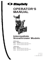
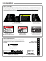
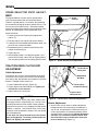
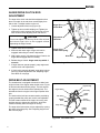
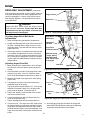
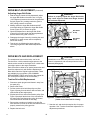
1
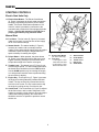
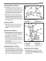
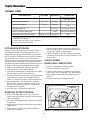
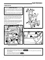
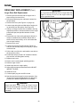
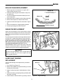
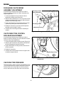
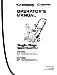
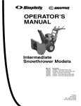
How to use this file...(Operators Manuals)
————————————————————————————————————————————–––
Instructions for
Print Vendors (Paper Manuals)
Paper Size:
* 11 x 17
* Body—50 lbs brilliant white offset or equivalent.
* Cover—on pre-printed two-tone “Swash” stock.
Press:
* Body—1-color, 2-sided
* Cover imprint —1-color, 1-sided
Bindery:
* Saddle Stitch, Face Trim, 3-Hole Drill
* Face Trim
COVERS:
* This file contains several manuals, which differ only in their covers.
* Covers are all present at the beginning of this file.
* Back cover for a particular manual is the page IMMEDIATELY AFTER the front cover.
• Check the front cover for the individual part number (typically a 171xxxx number).
BODY:
• The body of the manual is identical, regardless of the cover used.
* REMEMBER: ODD number pages are ALWAYS right hand pages, and EVEN number are ALWAYS
left hand pages.
General:
* This instruction page is NOT part of the manual and must NOT be printed.
• Pages labeled with the text “THIS PAGE INTENTIONALLY BLANK” are placement pages ONLY,
and should NOT be printed.
————————————————————————————————————————————–––
If you have further questions on how to utilize this file, please contact
Simplicity Technical Publications Department at (414) 284-8650.
THIS PAGE INTENTIONALLY BLANK
OPERATOR’S
MANUAL
Intermediate
Snowthrower Models
555 Models
Mfg. No.
1693161
1693163
1693425
Description
555M, 5HP Snowthrower, Manual Start
555M, 5HP Snowthrower, Manual Start (Export)
555M, 5HP Snowthrower, Manual Start
755 Models
Mfg. No.
1693162
1693164
1693426
Description
755E, 7HP Snowthrower, Electric Start
755M, 7HP Snowthrower, Manual Start (Export)
755E, 7HP Snowthrower, Electric Start
1717676-03
Rev 8/1998
TP 100-2062-03-IW-S
MANUFACTURING, INC.
500 N Spring Street / PO Box 997
Port Washington, WI 53074-0997
www.simplicitymfg.com
© Copyright 1998, Simplicity Manufacturing, Inc.
All Rights Reserved. Printed in USA.
Table Of Contents
REGULAR MAINTENANCE
Normal Care Chart ................................................12
Off-Season Storage ..............................................12
Starting After Storage ...........................................12
Checking Auger Gear Case Lubrication ...............12
Lubrication ............................................................13
SERVICE
Troubleshooting .............................................14 - 15
Speed Selector Pivot Adjustment .........................16
Traction Drive Clutch Rod Adjustment ..................16
Auger Drive Clutch Rod Adjustment .....................17
Drive Belt Adjustment ...........................................17
Adjusting Auger Drive Belt ....................................18
Adjusting Auger Belt Guide ...................................19
Replacing Drive Belts............................................19
Replacing Auger Drive Belt ...................................20
Roller Chain Replacement ....................................21
Shear Pin Replacement ........................................21
Auger Shaft Bearing Replacement .......................21
Discharge Chute Worm Assy. Adjustment ............22
Discharge Chute Control Rod Gear Adjustment ...22
Checking Tire Pressure ........................................22
SPECIFICATIONS ......................................................23
REPLACEMENT PARTS & ACCESSORIES ............ 24
TECHNICAL MANUAL AVAILABILITY .....................24
SAFETY RULES
General ...................................................................2
Preparation .............................................................2
Operation ................................................................3
Maintenance & Storage ..........................................3
Safety Decals ..........................................................4
CONTROL REFERENCE CHART
Snowthrower Controls.............................................5
Engine Controls ......................................................5
CONTROLS
Starting Controls .....................................................6
Ground Speed Controls ..........................................7
Auger Control ..........................................................7
Deflector Controls ...................................................7
Scraper Height Control ...........................................7
Traction Lock Control ..............................................7
OPERATION
General ...................................................................8
Checks Before Each Start-Up .................................8
Starting The Engine ................................................9
Operating The Snowthrower ...................................9
Engine Speed .......................................................10
Ground Speed Selector ........................................10
Deflector................................................................10
Scraper Bar & Skid Shoes ....................................10
Free Wheeling and Traction Drive Lock................11
After Each Use ......................................................11
For easy reference, please record the information on the chart below.
WARNING
You must read, understand and comply with all safety and operating instructions in this manual before
attempting to set-up and operate your snowthrower.
The Snowthrower Reference Data can be found on the
identification tag located on the unit’s rear frame. (Refer
to the Engine Owner’s Manual for location of engine
information serial number.)
Failure to comply with all safety and operating
instructions can result in loss of machine control,
serious personal injury to you and /or bystanders,
and risk of equipment and property damage. The triangle in the text signifies important cautions or warnings which must be followed.
SNOWTHROWER REFERENCE DATA
Model Description/Number
M/N (Manufacturer’s Number)
S/N (Serial Number)
Dealer Name
Date Purchased
WARNING
ENGINE REFERENCE DATA
Engine exhaust from this product contains chemicals
known, in certain quantities, to cause cancer, birth
defects, or other reproductive harm.
Engine Make/Model
© Copyright 1998 Simplicity Manufacturing, Inc. All Rights Reserved. Printed In USA.
TP 100-2062-03-IW-S
2062-03
1
Engine ID/Serial Number
Safety Rules
WARNING
WARNING
This unit is a “two-stage” snowthrower.
To avoid serious injury, do not put your hands into
the auger housing or discharge chute. If auger stalls
or chute becomes plugged, use the following procedure to remove objects or clear the chute:
The first stage is the auger, which feeds the snow
back into the impeller housing. The second stage is
the impeller, which throws the snow out the discharge chute. If bodily contact is made with the auger
or impeller when they are rotating, severe personal
injury will occur.
1.
2.
3.
4.
5.
6.
To avoid injury, keep others and yourself away from
the auger and the discharge chute whenever the
engine is running. Read and follow all of the safety
rules and warnings in this manual.
GENERAL
Release both the Drive and Auger Control levers.
Shut off the engine.
Remove the Engine Key.
Wait for moving parts to stop.
Disconnect spark plug wire.
Use a narrow board to remove foreign objects
and clear the chute or auger. Never put your
hands into the auger or discharge chute.
PREPARATION
• Read the Operator’s Manual carefully. Be thoroughly
familiar with all controls and proper equipment use.
• Never attempt to make any adjustment while engine
is running.
• Never allow children to operate the machine. Do not
allow adults to operate it without proper instruction.
• Thoroughly inspect the area where the snowthrower
is to be used and remove all objects such as door
mats, sleds, boards, wires and sticks.
• Keep the area of operation clear of all persons, particularly small children and pets.
• Disengage all clutches (release Drive and Auger
Control levers) before starting engine.
• Never discharge material toward any person or pet.
a. snowthrower is in good operating condition;
• Do not operate snowthrower without wearing proper
winter clothing. Wear footwear which improves footing on slippery surfaces.
b. all safety devices and shields are in place and
working;
• Adjust Skid Shoe height to clear gravel or crushed
rock surface.
c. all adjustments are correct.
• Handle gasoline with care - it is highly flammable.
• Make sure:
a. Use approved gasoline container.
b. Never remove the fuel tank cap or add gasoline to
a running or hot engine.
c. Never fill the fuel tank indoors.
d. Wipe up spilled gasoline.
• Do not run engine indoors. Exhaust fumes are deadly.
2
Safety Rules
OPERATION
MAINTENANCE & STORAGE
• Keep hands and feet away from rotating parts. Keep
clear of discharge opening at all times.
• Keep all nuts, bolts and screws tight to ensure that
the equipment is in safe operating condition.
• Always clear snow up and down the face of slopes,
never across the face. Use extreme caution when
changing direction on slopes. Do not attempt to clear
slopes over 17.7% (10o).
• Never store equipment with gasoline in the tank in a
building where fumes may reach an open flame or
spark. Allow the engine to cool before storing in any
enclosure.
• Use extreme caution when operating on or crossing
gravel drives, walks or roads. Stay alert for hidden
hazards and traffic.
• Always refer to the Operator’s Manual for important
details if snowthrower is to be stored for an extended
period.
• Be especially careful not to touch snowthrower parts
which might be hot from operation. Allow such parts
to cool before attempting to maintain, adjust or service.
• Run auger drive a few seconds after completion of
throwing snow to help clear out snow and prevent
icing and freeze-up on unit.
• If unit starts to vibrate abnormally, disengage drives
and stop the engine. Check immediately for the
cause. Vibration is generally a warning of trouble.
• Before leaving operator’s position for any reason:
- shut off engine,
- remove the Engine Key and
- wait for all moving parts to stop.
• Before cleaning, repairing or inspecting the unit,
make certain all moving parts have stopped. Remove
the key and then disconnect the spark plug wire to
prevent accidental starting.
• Always use a grounded, 3-wire plug receptacle for
electric starting.
• Adjust snow discharge angle for safe flow when operating near glass enclosures, automobiles, window
wells, dropoffs, etc.
• Do not overload machine capacity by clearing snow
at too fast a ground speed.
• Never operate machine at high transport speeds on
slippery surfaces. Use care when backing up.
• Disengage Auger Control when transporting or not in
use.
• Never operate the snowthrower without good visibility
or light. Always be sure of your footing.
• Do not change the engine governor settings or overspeed the engine.
• Never direct the discharge chute at bystanders; nor
allow anyone in front of the unit while it is operational.
• Never operate this machine without all of the proper
guards or other safety protective devices in place.
3
Safety Signs & Decals
SAFETY DECALS
Safety warning decals are placed at strategic locations on the snowthrower as a constant reminder to the operator of the most important safety precautions. All warning, caution and instructional messages on your snowthrower should be carefully read and obeyed. If any of these decals are lost or damaged, replace them at once. They
can be purchased from your local dealer.
WARNING
TO AVOID SERIOUS INJURY
• Read Owner’s Manual before operating unit.
• Never allow children to operate snowthrower.
• Always direct discharge chute so as to avoid injury
to persons—or damage to property
• Stop engine and disconnect spark plug wire before
removing debris or servicing unit.
• Keep all shields and guards in place while running.
Part No. 1715555
Auger Control Decal
Part No. 1715556
WARNING / Main Dash Decal
DANGER
DANGER
AVOID INJURY
FROM ROTATING
BLOWER!
Shut off engine
before unclogging
discharge chute.
1716533
Part No. 1716533
Discharge Chute Danger Decal
AVOID INJURY
FROM ROTATING
AUGER!
Keep hands, feet,
and clothing away.
1716532
Part No. 1716532
Auger Danger Decal
Engine "Hot" Decal
Decal supplied by the engine manufacturer.
See your local Tecumseh dealer.
ADDITIONAL DECALS
Additional decals used on this unit are also available, and may
be desired as replacement parts to maintain the performance
and value of your unit. These can also be purchased from your
local dealer.
Part No. 1715557
Speed Selector Decal
Part No. 1715558
Simplicity Logo Decal
TOUCH-UP PAINT PART NUMBERS
13 Oz. Spray Can Paint
Deep Orange
Gloss Black
1/2 Oz. Touch-Up Bottle
Deep Orange
7
SNO-AWAY
55cm
1685611
1685639
1685615
Part No. 1709061
Touch-Up Paint ID Decal
Part No. 1714107 (755) Or Part No. 1714108 (555)
Simplicity Logo Auger Decal
4
Control Reference Chart
SNOWTHROWER CONTROLS
A
Speed
Selector
Selects Forward Speeds 1 - 5,
Reverse Speeds 1 - 2
B
Drive Control
Engages drive to wheels as it is
depressed; disengages when
released.
D
A
C
Auger Control
Engages auger/impeller as it is
depressed; disengages when
released.
D
Chute Direction
Control
Rotates discharge chute to
desired direction
E
Chute
Deflector
Controls vertical angle snow is
thrown.
F
Chute
Deflector Knob
Locks chute deflector at desired
angle
B
C
E
F
H
G
G Skid Shoes
H
Traction
Lock Pins
Controls height of scraper bar
Engages for drive and
disengages for free-wheeling
Figure 1.
Snowthrower Controls
ENGINE CONTROLS
A
Electric Start
Button
(Optional)
Activates electric starter
B Fuel Valve
Turns fuel supply on or off.
C Starter Handle
Used to start engine
D Primer Button
Primes carburetor for faster cold
starting.
E
Throttle Lever
Controls engine speed
F
Engine Key
Prevents starting of engine without key. Stops engine when
removed.
A
B
C
D
G Choke Knob
G
Adjusts air/fuel mixture
Figure 2.
5
Engine Controls
F
E
Controls
STARTING CONTROLS
B
Electric Start Units Only
*
A
A. Electric Start Button - The Electric Start Button
(A, Figure 3) activates an electric starter mounted to
the engine, eliminating the need to pull the starter
handle. The Electric Start Button operates on 120
Volts AC, which is provided by connection to the
extension cord provided with units equipped with this
feature. Connect this extension cord ONLY to a
properly grounded 3 prong electrical outlet.
C
Manual Start
B. Fuel Valve - The fuel valve (B, Figure 3) is located
under the fuel tank. It is used to turn the fuel supply
off for out-of-season storage.
D
C. Starter Handle - The starter handle (C, Figure 3)
connects to a starter cord to manually start the
engine. Pulling starter handle rapidly spins the engine
crankshaft, cycles the engine, and generates the
spark necessary for starting the engine.
G
Figure 3.
A.
D. Primer Button - When pressed, the primer button
(D, Figure 3) provides initial fuel to help start a cold
engine. Normally, pressing the primer button twice
will provide enough fuel to start a cold engine.
B.
E. Throttle Lever - The throttle lever (E, Figure 3) controls the engine speed. For best overall performance,
the throttle lever should be set to the FAST position.
Use the SLOW position only for warming the engine,
or to help prevent snow/ice freeze-up when shutting
the unit down for the day.
F. Engine Key - The Engine Key (F, Figure 3) prevents
the engine from being started by unauthorized individuals. The key must be fully inserted into the key
slot for the unit to start. The key is also used to stop
the engine by pulling the key out of the key slot.
G. Choke Knob - The Choke Knob (G, Figure 3) adjusts
the air/fuel mixture, and is used to help start a cold
engine by providing a richer mixture. Once the engine
is warm and running smoothly, the Choke Knob
should be set to the off position to provide a normal
air/fuel mix.
6
F
E
Engine Controls
Electric Start Button
(On some units only)
Fuel Valve
* 7 HP Engine - Lower
Front Gas Tank Area
* 5 HP Engine - Lower
Rear Gas Tank Area
C.
D.
E.
F.
G.
Starter Handle
Primer Button
Throttle Lever
Engine Key
Choke Knob
Controls
GROUND SPEED CONTROLS
A
FRONT
A. Speed Selector - This lever (A, Figures 4 & 5) is
used to set the ground speed of the snowthrower.
The snowthrower has five forward speeds, 1–5, and
two reverse speeds, 1–2. No neutral position or gate
is required, since the traction drive design automatically provides "neutral" (no forward or reverse movement), whenever the Drive Control is released.
B. Drive Control - This control engages the traction
drive as the lever (B, Figures 4 & 5) is depressed,
and disengages the traction drive when the lever is
released. The traction drive provides power to the
wheels. NOTE: Changing ground speeds must only
be done while the Drive Control is in the disengaged
(fully released) position.
D
B
Figure 4.
C
Operator's Control Position
A. Speed Selector
B. Drive Control
C. Auger Control
D. Chute Direction Control
AUGER CONTROL
A
C. Auger Control - The Auger Control clutch lever (C
Figures 4 & 5), engages the auger drive (which
throws the snow) as the lever is depressed, and
disengages the auger drive when the lever is
released.
D
B
C
E
DEFLECTOR CONTROLS
D. Chute Direction Control - The Chute Direction
Control (D, Figures 4 & 5), allows the discharge chute
to be rotated to throw snow in the desired direction.
Snow may be thrown at any angle from straight left,
to straight forward, to straight right.
F
H
E. Chute Deflector - Controls the distance snow is
thrown. Tilting the Chute Deflector (E, Figure 5) UP
provides a higher stream and greater distance, while
tilting the deflector DOWN provides a lower stream
and less distance.
G
Scraper Bar
Figure 5.
F. Chute Deflector Knob - This knob (F, Figure 5)
allows the discharge Chute Deflector (E, Figure 5) to
be locked in the desired tilt position.
A.
B.
C.
D.
SCRAPER HEIGHT CONTROL
G. Scraper Bar Height Control - The Skid Shoes (G,
Figure 5) control the height the scraper bar (located
at the bottom of the auger housing). The scraper bar
allows smooth surfaces (such as concrete or asphalt
driveways) to be scraped clean of snow. On surfaces
such as gravel, the scraper bar should be adjusted
higher — so that it will not pick up gravel or debris.
Snowthrower Operating Controls
Speed Selector
Drive Control
Auger Control
Chute Direction Control
E.
F.
G.
H.
Chute Deflector
Chute Deflector Knob
Skid Shoes
Traction Lock Pins
TRACTION LOCK CONTROL
H. Traction Lock Pins - The traction drive to each
wheel can be locked and unlocked with the Traction
Lock Pins (H, Figure 5) to permit the unit to “freewheel,” allowing easier manual handling and transport
of the snowthrower.
7
Operation
GENERAL OPERATION
CHECKS BEFORE EACH START-UP
WARNING
1. Make sure all safety guards are in place and all nuts,
bolts and clips are secure.
To avoid serious injury, do not put your hands into
the auger housing or discharge chute. If auger stalls
or chute becomes plugged, use the following procedure to remove objects or clear the chute:
2. Check the engine oil level. See your engine Owner’s
Manual for procedure and specifications.
1.
2.
3.
4.
5.
6.
3. Check to make sure spark plug wire is attached and
spark plug is tightened securely. If necessary, torque
spark plug to 15 ft. lbs.
4. Check the fuel supply. Fill the tank no closer than 1/4
to 1/2 inch of top of tank to provide space for expansion. See your engine Owner’s Manual for fuel recommendations.
5. Check the Scraper Bar to make sure it is set at the
desired height. Adjust the Skid Shoes if necessary.
(See page 10.)
Release both the Drive and Auger Control levers.
Shut off the engine.
Remove the Engine Key.
Wait for moving parts to stop.
Disconnect spark plug wire.
Use a narrow board to remove foreign objects
and clear the chute or auger. Never put your
hands into the auger or discharge chute.
WARNING
6. Check the Drive Control (B, Figure 1), and Auger
Control (C, Figure 1) for proper operation. If adjustment is required, see the Service section (pages 1617) for procedures.
For your safety, operation on slopes should be in an
up and down direction only. If it becomes necessary
to move across the face of a slope, use caution and
do not blow snow. Be very careful when changing
direction on a slope.
7. Check the Chute Direction Control (D, Figure 1) for
proper operation. The discharge chute should rotate
freely in both directions. See the Service section for
adjustment procedures and troubleshooting.
Proper winter footwear is recommended for the
operator to help prevent slipping. Never attempt to
clean snow from excessively steep slopes. The
maximum slope for any operation is 17.7% (10º).
8. Check the Chute Deflector (E, Figure 1) for proper
operation. The deflector should pivot freely up and
down when the Chute Deflector Knob is loosened. If
adjustment is required, see the Service Section for
procedures.
WARNING
9. Position the chute at the desired starting direction
and set the deflector at the desired angle.
Gasoline is highly flammable and must be handled
with care. Never fill the tank when the engine is hot or
running. Always move outdoors to fill the tank. Keep
snowthrower and gasoline away from open flame or
spark.
10. Check the Speed Selector (A, Figure 1) for smooth
operation. The control must move freely into each
speed position gate and remain in position when
released. If the Speed Selector does not move freely
into all forward and reverse speed positions, contact
your local authorized dealer for assistance.
8
Operation
STARTING THE ENGINE
B
1. Turn the fuel valve (B, Figure 6) to the ON position.
*
A
2. Insert the Engine Key (F, Figure 6) into the Engine
Key slot and push fully in to the RUN position.
C
3. Move the Throttle Lever (E, Figure 6) fully up to the
FAST position.
4. Turn the Choke Knob (G, Figure 6) fully clockwise if
engine is cold. (Do not choke a warm engine.)
5. Push the Primer Button (D, Figure 6) two times if
engine is cold. (Do not prime a warm engine.)
6. Pull Starter Handle (C, Figure 6) rapidly, or push
Starter Button if equipped with the electric start. Do
not allow the Starter Handle to snap back—let the
starter rope rewind slowly—while keeping a firm grip
on the Starter Handle.
D
7. As the engine starts and begins to operate evenly,
turn the Choke Knob (G, Figure 6) slowly counterclockwise to the OFF position, and set the Throttle
Lever to SLOW. If the engine falters, turn the Choke
Knob clockwise until the engine runs smoothly, and
let it run briefly before returning the choke to the OFF
position.
G
Figure 6.
A.
B.
NOTE: Allow the engine to warm up at SLOW throttle for
a few minutes before operating the snowthrower at full
speed. The engine will not develop full power until it
reaches operating temperature.
E
F
Engine Controls
C.
D.
E.
F.
G.
Electric Start Button
(On some units only)
Fuel Valve
* 7 HP Engine - Lower
Front Gas Tank Area
* 5 HP Engine - Lower
Rear Gas Tank Area
Starter Handle
Primer Button
Throttle Lever
Engine Key
Choke Knob
OPERATING THE SNOWTHROWER
A
FRONT
1. Rotate the discharge chute to the desired direction.
2. Set the Speed Selector to the desired forward speed.
3. Fully press and hold the Auger Control (C, Figure 7)
on the right-hand grip to begin auger rotation. To disengage the auger, completely release the lever.
4. Fully press and hold the traction Drive Control lever
(B, Figure 7) on the left-hand grip to engage the traction drive and begin moving the snowthrower. To disengage the traction drive, completely release the
lever.
B
5. Select forward or reverse speeds as needed using
the Speed Selector (A, Figure 7). Release the Drive
Control lever whenever changing drive speeds.
Figure 7.
9
C
Operator's Control Position
A. Speed Selector
B. Drive Control
NOTE: After 5 - 10 hours of use, it may be necessary
to adjust the tension on the traction drive rod. See
"Traction Drive Clutch Rod Adjustment" in the
Service Section for the adjustment procedure.
D
C. Auger Control
D. Chute Direction Control
Operation
ENGINE SPEED
Throttle
Lever
For overall best performance, run the snowthrower at full
engine operating speed. Use the engine Throttle Lever
(See Figure 8) to set the engine speed. Slide the Throttle
Lever UP to increase engine speed, and DOWN to
reduce speed.
GROUND SPEED SELECTOR
Use the Speed Selector (A, Figure 7) to control the drive
speed of the snowthrower. There are five forward speeds
and two reverse speeds.
Use the lower speeds to blow deep or wet snow. Use the
higher speeds to blow light snow or to drive the snowthrower without blowing snow.
Figure 8.
To change speeds, first release the traction Drive Control
lever (B, Figure 7), then move the Speed Selector to the
desired speed setting. Fully press the traction Drive
Control lever to resume operation.
Engine Speed Selection
Chute
Deflector Knob
DEFLECTOR
The distance of the discharged snow is mainly controlled
by the position of the deflector (Figure 9). (Engine speed
also affects distance of discharge.)
The more the deflector is tilted UP, the farther snow will
be thrown. Loosen the deflector knob, tilt the deflector
UP or DOWN, and then retighten the knob when the
desired angle has been chosen.
Chute
Deflector
SCRAPER BAR & SKID SHOES
On smooth surfaces such as concrete or asphalt, the
scraper bar should scrape the surface. On surfaces such
as gravel, the scraper bar should be high enough so that
it will not pick up gravel or debris.
Figure 9.
Chute Deflector Adjustment
The height of the scraper bar is controlled by raising or
lowering the Skid Shoes (See Figure 10).
1. To raise the scraper bar height, rest the scraper bar
on a strip of wood equal in thickness to the desired
height.
2. Make sure the scraper bar is parallel to the ground
surface.
3. Loosen the skid shoe nuts and let the skid shoes
drop to the surface.
Scraper
Bar
4. Tighten the nuts, making sure the Skid Shoes are
adjusted equally and are parallel to the surface.
Skid Shoe
Nuts
5. To lower the height of the scraper bar, raise the Skid
Shoes.
Skid Shoe
6. If the scraper bar becomes worn, it can be replaced
by removing the hardware attaching it to the
snowthrower.
Figure 10. Skid Shoe Adjustment
10
Operation
FREE-WHEELING AND
TRACTION DRIVE LOCK
For easy turning when pushing the snowthrower, you
can disengage the traction drive at one or both wheels
by using the Traction Lock Pins (See Figures 11 & 12.)
1. Turn the unit off, remove the Engine Key, and disconnect the spark plug wire.
Klik-Pin In
OUTER Hole
2. To DISENGAGE the traction drive lock, insert the
Traction Lock Pin through the outer hole in the axle.
(See Figure 8).
3. To ENGAGE the traction drive lock, insert the pin
through the hub and axle (See Figure 9). If the hole in
the hub is not aligned with the inner hole in the axle,
push the snowthrower until the holes align and install
the Traction Lock Pin.
NOTE: When snowthrowing with the full width of the
auger, for best drive performance engage both wheels.
For easier turning when not using the full width of the
auger, engage one wheel and use the engaged side as
the snow contact side for the auger.
Figure 11. Traction Drive Lock - Disengaged
AFTER EACH USE
Klik-Pin In
INNER Hole
Normal use of the snowthrower may result in a build-up
of packed snow in and around the starter cord housing
and around engine controls. Heat from the engine will
usually prevent the snow from freezing solid while the
unit is running, but after the engine is shut down, some
snow may continue melting from engine heat, and later
freeze around some moving parts as the unit cools.
After each period of use, follow these steps to prevent
freeze-up caused by ice formation in and around the
engine controls and external parts.
1. Before shutting off the engine, pull the starter rope
out 2 - 3 times, and allow it to rewind slowly. This will
help clear packed snow from the starter cord area.
Figure 12. Traction Drive Lock - Engaged
2. Stop the engine by moving the Throttle Lever (See
Figure 8) down, or by pulling out the Engine Key.
WARNING
3. Disconnect the spark plug wire, and position it away
from the spark plug.
Never store snowthrower, with gasoline in engine or
fuel tank, in a heated shelter or in enclosed, poorly
ventilated enclosures. Gasoline fumes may reach an
open flame, spark or pilot light (such as a furnace,
water heater, clothes dryer, etc.) and cause an explosion.
4. Brush snow and ice from the snowthrower. Be sure to
clear engine and snowthrower controls, discharge
chute, worm and chute rod gears, clutch rod areas,
and anywhere else snow has accumulated.
5. Always remove the Engine Key and store in a safe
place to prevent unauthorized use.
Handle gasoline carefully. It is highly flammable and
careless use can result in serious fire damage to
people and property.
6. If the snowthrower is kept in a cold shelter, fill the fuel
tank to prevent condensation. Do not store near
sparks or flame.
Drain fuel into an approved container outdoors away
from open flame or sparks.
Note: The Engine Owner’s Manual contains further information on preventing ice formation and freeze-up.
11
Regular Maintenance
NORMAL CARE
CARE REQUIRED
SEE PAGE
FREQUENCY
Check auger gear case lubrication.*
Page 12
25 Hours
Simplicity Winter Weight
Worm Gear Oil
Lubricate snowthrower.
Page 13
10 Hours
10W Oil and Grease
Check tire pressure.
Page 22
Monthly
N/A
Change engine oil.**✛
-
50 Hours✛
See Engine Manual
Clean or replace spark plug.✛
-
Yearly
See Engine Manual
Page 16-19
4-6 Hours
N/A
Check drive linkage/belt tension
LUBRICATION
* The auger gear case has been factory lubricated for life. If lubricant should leak out, have auger gear case
inspected by your dealer.
** Change original oil after two hours of operation.
✛ See your engine Owner’s Manual.
5. Start the engine outdoors. Warm up engine by running at SLOW speed for a a few minutes before running at FAST speed, or blowing snow.
6. Check the operation of all the controls. If necessary,
lubricate the snowthrower to improve operation of the
chute control.
OFF-SEASON STORAGE
Before you store your snowthrower for the off-season,
read the Maintenance and Storage instructions in the
Safety Rules section and take the following precautions:
NOTE: Gasoline, if permitted to stand unused for extended periods (30 days or longer), may develop gummy
deposits which can adversely affect the engine carburetor
and cause engine malfunction. To avoid this condition,
add Simplicity Gasoline Stabilizer to the fuel tank, or drain
all fuel from the system before placing unit in storage.
CHECK AUGER
GEAR CASE LUBRICATION
1. Place the snowthrower on a level surface.
1. Prepare your snowthrower engine for storage as
instructed in the Engine Owner’s Manual.
2. Remove the Pipe Plug (Figure 10).
3. Check the lubricant level. It should be level with the
lower edge of the plug opening. If not, add Simplicity
Winter Weight Worm Gear Oil (available from your
dealer).
2. Lubricate the snowthrower as described in the LUBRICATION section of this manual (page 13).
3. Clean the snowthrower thoroughly. Coat exposed bare
metal parts with a quality paint (available from you
dealer) or a light film of grease, oil or automotive wax.
4. Re-install Pipe Plug, and tighten securely.
4. Store snowthrower in the wheels down, operating
position. Note: If the unit is stored in any other position, oil from crankcase could enter cylinder head,
causing a service problem.
Pipe Plug
5. Store the unit in a protected area and cover.
STARTING AFTER STORAGE
1. Remove the spark plug and wipe dry. Crank the
engine a few times to blow excess oil out of plug hole.
Then reinstall plug.
2. Fill fuel tank with fresh gasoline (unless a fuel stabilizer was used).
3. Check to be sure engine fins are clean and air flow is
unobstructed.
4. Check engine oil level and lubricate snowthrower.
Change oil if necessary.
Figure 13. Checking Auger Gear Case Lubrication
12
Regular Maintenance
LUBRICATION
IMPORTANT NOTE
It is very important that grease fittings on the auger
shaft are lubricated regularly. If auger rusts to shaft,
damage to worm gear may occur if shear pins do not
break.
To prevent wheels rusting to axles, it is also necessary
to remove the wheels and grease the axles regularly.
There are two grease fittings on the auger shaft (Figure
15). Wipe the fittings clean and apply grease, using a
grease gun. Also apply grease on other points indicated.
Apply medium weight (10W) oil to points shown(See
Figures 14 - 16).
Generally, all moving metal parts should be oiled where
contact is made with other parts. Keep oil and grease off
belts, pulley grooves, drive disc, and friction disc.
See lubrication notes at bottom of page.
Figure 15. Snowthrower General Lubrication Points
Drive Disc
Friction Disc
Figure 16. Chute Control Rod Gears
Figure 14. Drive Area Lubrication Points
(Bottom Cover Removed)
LUBRICATION NOTES:
01
1.
Grease locations indicated by grease gun symbol:
Use grease fittings when present. Disassemble parts to apply grease to moving parts when grease fittings
are not installed.
2.
Oil locations indicated by oil can symbol:
Do not allow oil to drip onto traction drive or friction disc.
13
Service
TROUBLESHOOTING
This section provides troubleshooting and service
instructions. Locate the problem and check the possible
cause/remedy in the order listed.
WARNING
Before performing any adjustment or service to
snowthrower, stop the engine and wait for moving
parts to stop. Remove the key. To prevent accidental
starting, disconnect the spark plug wire and fasten
away from the plug.
Also, refer to the engine manufacturer’s Owner’s Manual
for additional information.
For problems not covered here, contact your local dealer.
PROBLEM
Engine fails to start.
POSSIBLE CAUSE
1.
2.
3.
4.
5.
Key is OFF.
Failure to Prime cold Engine
Fuel valve is in CLOSED position.
Out of fuel.
Choke OFF - cold engine.
6. Engine flooded.
7. Spark plug not sparking.
8. Water in fuel, or old fuel.
Engine starts hard or runs poorly.
Auger does not rotate.
REMEDY
1.
2.
3.
4.
5.
Push key in to the ON position.
Press Primer Button twice and restart.
Turn valve to OPEN position.
Fill fuel tank.
Turn choke to ON, set throttle to
FAST.
6. Turn choke to OFF; try starting.
7. Check gap. Gap plug, clean electrode, or replace plug as necessary.
8. Drain tank (Dispose of fuel at an
authorized hazardous waste facility).
Fill with fresh fuel.
1. Fuel mixture too rich.
1. Move choke to OFF position.
2. Carburetor adjusted incorrectly.
2. See your dealer for adjustments.
3. Spark plug faulty, fouled, or gapped
improperly.
3. Clean and gap, or replace.
1. Auger Control not engaged.
2. Foreign matter blocking auger.
1. Engage Auger Control.
3. Auger drive clutch rod slack.
4. Auger drive belt slipping.
5. Broken belt.
6. Shear pin broken.
14
2. STOP engine and REMOVE the key.
DISCONNECT the spark plug wire.
Clear auger using a narrow board.
See warning in SAFETY RULES.
3. Tighten to remove slack. See auger
clutch rod adjustment.
4. Check auger drive belt adjustment.
5. Replace belt.
6. Replace shear pin.
Service
PROBLEM
POSSIBLE CAUSE
REMEDY
1. Chute deflector too low.
1. Adjust deflector as necessary.
2. Engine speed too slow.
2. Set speed to full throttle.
3. Ground speed too fast.
4. Snowthrower discharge chute clogged.
3. Use slower Speed Selector setting.
4. STOP engine and REMOVE the key.
DISCONNECT the spark plug wire.
Clear auger using a narrow board.
See warning in SAFETY RULES.
5. Auger belt loose or worn.
5. Check Auger Drive Belt Adjustment
Scraper bar does not clean hard
surface.
1. Skid Shoes improperly adjusted.
1. RAISE Skid Shoes (this lowers the
Scraper Bar).
Scraper bar picks up and throws
stones on gravel drive.
1. Skid shoes improperly adjusted.
1. LOWER Skid Shoes (this raises the
scraper bar.)
Poor traction
1. Tires slipping.
1. Check tire pressure and tread.
Auger does not stop when auger
lever is released
1. Auger clutch rod too tight or bent.
2. Auger drive belt out of adjustment.
3. Auger belt guide out of adjustment.
1. Loosen or straighten clutch rod.
2. Adjust auger belt.
3. Adjust auger belt guide.
Snowthrower does not stop when
drive lever is released
1. Traction drive clutch rod bent or too
tight.
1. Loosen rod to remove slack or
replace. See adjustment procedure.
Snowthrower does not drive when
drive lever is engaged.
1. Traction drive clutch rod loose.
1. Tighten to remove slack. See adjustment procedure.
2. Replace drive belt.
3. Replace chain.
4. Change Traction Lock Pins to INNER
hole to engage traction drive.
Auger rotates, but snow is not
thrown far enough
2. Drive belt loose, broken, or stretched.
3. Drive roller chain damaged.
4. Traction Lock Pins in Free-Wheeling
position (OUTER hole).
Discharge control is difficult to
operate.
1. Gearing needs lubrication
2. Worm gear not adjusted properly.
3. Control rod gears misaligned.
1. Oil or grease as required.
2. Adjust worm gear. See adjustment
procedure.
3. Adjust gear bracket. See adjustment
procedure.
Snowthrower veers to one side.
1. Tires pressure not equal.
2. One wheel is set in Free-Wheeling
mode. (Traction Lock Pin is in the
OUTER hole).
1. Check tire pressure.
2. Make certain BOTH Traction Lock
Pins are in the INNER holes (to
engage traction drive).
Excessive vibration.
1. Loose parts or damaged auger.
1. STOP engine and REMOVE the key.
DISCONNECT the spark plug wire.
Tighten all hardware. Replace auger
if necessary. If vibration continues,
see your dealer.
Drive fails to move snowthrower
at slow speeds.
1. Traction Drive out of adjustment.
1. Readjust drive, or shift Speed
Selector setting up one speed faster.
15
Service
SPEED SELECTOR PIVOT ADJUSTMENT
Speed
Selector
The Speed Selector is factory set for optimal performance at each forward and reverse speed setting.
However, if speed position 1 is too slow, the speed can
be increased by changing the pivot position one turn. Do
not turn pivot more than one turn - increasing forward
speed using this method reduces reverse speed by a like
amount, and inadequate reverse speeds will result.
Hitch Clip Pin
Adjust as follows:
1. Loosen pivot jam nut to permit pivot adjustment
(Figure 17).
Pivot
2. Pull hitch clip pin out of pivot and remove washer.
3. Looking at end of threaded Speed Selector shaft, turn
pivot one turn counter-clockwise.
Jam Nut
4. Reassemble pivot to control arm and secure with
washer and hitch clip pin.
5. Tighten jam nut.
6. Check speed position 1 for adequate speed. If unit
still moves too slowly, return pivot to original position
and use speed position 2 as a starting speed in place
Figure 17. Speed Selector Pivot Adjustment
TRACTION DRIVE CLUTCH ROD
ADJUSTMENT
Traction Drive
Clutch Rod
Initial Adjustment
The traction drive clutch rod should initially be adjusted
so that there is no slack in the rod when moved slightly
from side to side, but bellcrank arm remains in fully down
position. To adjust tension on the rod:
Adjustment
Hex Nuts
1. Loosen adjustment hex nuts (Figure 18).
Traction Drive
Clutch Rod Spring
2. Tighten top hex nut while holding rod. Tighten just
until slack in rod is removed.
3. Tighten lower hex nut securely.
Traction Drive
Bellcrank Arm
CAUTION
Figure 18. Traction Drive Clutch Rod Adjustment
Do not over-tighten, as this may cause traction drive
to engage without depressing the traction Drive
Control (bellcrank arm must remain in down position).
Run-In Adjustment
1. After 5 hours of use, check for proper adjustment.
Readjust clutch rod if necessary by increasing tension on rod. A small amount of bellcrank arm movement is permissible if unit passes operating checks
described in the Caution at left. Optimal adjustment
provides 1/32" clearance between traction drive
disc and rubber ring on friction disc when drive
lever is released (see Figure 14).
Verify that the rods are not overtightened: With Speed
Selector in position 1 and traction Drive Control fully
released, push snowthrower forward. The unit should
move forward freely.
If unit does not move forward freely, the rod has
been over-tightened. To remedy, loosen tension on
clutch rod slightly, and recheck.
16
Service
AUGER DRIVE CLUTCH ROD
ADJUSTMENT
The auger drive clutch rod should be adjusted so that
there is no slack in the rod when moved slightly from
side to side. To adjust tension on the rod:
Auger Drive
Clutch Rod
1. Loosen adjustment hex nuts (Figure 19).
2. Tighten top hex nut while holding rod. Tighten just
until slack in rod is removed. Be careful not to move
idler rod lever when adjusting clutch rod tension.
CAUTION
Adjustment
Hex Nuts
Do not over-tighten, as this may lift the idler rod lever
and cause auger drive to be engaged without
depressing the Auger Control.
3. Tighten lower hex nut securely.
Auger Drive
Clutch Rod Spring
4. Start unit and check auger. Auger must not be
engaged unless Auger Control is depressed.
5. With engine running, fully depress Auger Control, the
auger should engage and run normally.
Idler Rod
6. Release Auger Control. Auger must stop within 5
seconds.
Right Handle
Figure 19. Auger Drive Clutch Rod Adjustment
7. If auger does not operate properly, stop engine and
recheck clutch rod adjustments.
8. If clutch rod is properly adjusted, auger drive belt tension may require adjustment. See "Adjusting Auger
Drive Belt" on next page.
DRIVE BELT ADJUSTMENT
The snowthrower is equipped with two drive belts located just in front of the engine under the belt cover. Figure
20 shows both belts and idler pulleys. The belt nearest
the engine is the unit traction drive (wheels) belt. The
belt farthest from the engine is the auger/ impeller drive
belt.
Engine Pulley
Engine Pulley
Idler Pulley
The traction drive belt has constant tension provided by
a spring-loaded idler pulley arm, and is non-adjustable.
This belt rotates whenever the engine is running, and
provides power to the traction drive disc, which also
rotates constantly while the engine is running.
AUGER
BELT
DRIVE
BELT
Traction
Drive Pulley
Auger Pulley
The auger drive belt tension may be adjusted by moving
the auger drive idler pulley. See "Adjusting Auger Drive
Belt’ on next page.
FRONT
(Auger)
Figure 20. Drive Belt Paths
01
Idler Pulley
17
Service
DRIVE BELT ADJUSTMENT (Continued)
If the auger drive slips (auger slows or doesn't rotate normally while blowing snow), or stays engaged when the
control is disengaged — and the auger clutch rod has
been properly adjusted — the auger drive belt may be
out of adjustment.
Auger Control
Belt Cover
WARNING
Auger must NOT rotate unless the Auger Control
lever has been depressed. Proper Auger Drive Belt
adjustments stop the auger within 5 seconds after
the Auger Control is disengaged.
Figure 21. Auger Control and Belt Cover Location
Checking Auger Belt & Belt Guide
Adjustments
Auger Drive
Clutch Rod
1. Insert the Engine Key and start the Snowthrower.
Adjustment
Hex Nuts
2. Engage and disengage the Auger Control a series of
ten times, checking that the auger comes to a complete stop within 5 seconds after the control is disengaged each time.
Auger Drive
Clutch Rod Spring
3. If the auger comes to a complete stop each time within 5 seconds, the adjustment is correct. If the auger
does NOT come to a complete stop within the necessary 5 seconds, the adjustment is incorrect: readjusting the Auger Belt & Belt Guide according to the procedures below.
Measure Spring
Length, Spring
Should Expand
5/16” When Auger
is Engaged
Adjusting Auger Drive Belt
Idler Rod
1. Make certain that the snowthrower is off, the Engine
Key has been removed, and the spark plug disconnected.
Right Handle
Figure 22a. Auger Drive Clutch Rod
2. Check that there is no slack in the auger drive clutch
rod (see Figure 22a). If there is, follow the Auger
Drive Clutch Rod Adjustment procedure on page 17.
Auger Idler
Pulley
3. Measure the length of the auger drive clutch spring
(Figure 22a).
4. Fully depress the auger control and measure the
expanded length of the spring.
Auger Idler
Arm
The spring should expand 19/64”-5/16”. If the spring
deflection is less than 19/64”-5/16” the auger idler
pulley must be adjusted. Proceed to step 5.
Adjustment
Bolt
5. Using a 3/8” wrench, loosen the Belt Cover screws
and remove the Belt Cover.
6. Loosen the adjustment bolt (see Figure 22b) and
move the auger idler pulley.
7. Tighten the adjustment bolt and repeat steps 3-4.
Auger
Drive Belt
Figure 22b. Auger Drive Belt, Guide and Pulley
8. Test run the unit. The auger must NOT rotate unless
the Auger Control lever has been depressed. Proper
Auger Drive Belt adjustments stop the auger within 5
seconds after the Auger Control is disengaged. If the
auger drive fails either of these tests, loosen the idler
pulley.
9. After adjusting the Auger Drive Belt, the Auger Belt
Guide MUST BE adjusted according to the Adjusting
Auger Belt Guide procedure which follows.
18
03
Service
DRIVE BELT ADJUSTMENT (Continued)
Adjusting Auger Belt Guide
WARNING
1. With the Auger Control still fully depressed, adjust
the Auger Belt Guide so that there is a 1/64” gap
(1/32” Maximum) between the end of the guide and
the belt (Figure 22c), making certain the guide is
NOT putting pressure on the belt.
2. Making certain the Auger Belt Guide does NOT
move while doing so, tighten the Auger Belt Guide
Screw (Figure 22c) to secure the guide.
3. Check the adjustment on the Auger Belt Guide
(Figure 22c) to make certain that the gap between
the belt and the belt guide is correct.
4. Disengage the Auger Control by removing the cardboard tube (or other means used to temporarily
secure the control.)
5. Test the unit by following the steps under the
“Checking Auger Belt & Belt Guide Adjustments”
above.
Failure to properly adjust the Auger Belt Guide
may cause auger to rotate when Auger Control
has not been depressed.
Belt Guide
& Gap
Belt Guide
Screw
Figure 22c. Auger Belt Guide Adjustment
DRIVE BELTS AND REPLACEMENT
CAUTION
The snowthrower has two drive belts, one for the
Traction Drive—which transmits engine power to the
wheels, and a second for the Auger Drive—which transmits engine power to the auger mechanism.
Snowthrower must move only when the traction Drive
Control is depressed, and must stop when the lever is
released (disengaged).
Each of these drive belts are of special construction and
should be replaced only with Genuine Replacement
Belts which match the original equipment belts. These
are available from your dealer. (See COMMON
REPLACEMENT PARTS at the back of this manual for
the correct part numbers for each of the belts.)
Traction Drive Belt & Pulley
Traction Drive Belt Replacement
1. Disconnect spark plug wire and fasten it away from
the spark plug.
2. Remove belt cover.
3. Pull the traction drive belt idler pulley arm (See
Figure 22) away from the belt to relieve tension, and
slide the belt off the engine pulley.
4. Slip the belt off from around the traction pulley (See
Figure 23) and pull the belt out of the unit between
the auger pulley and the traction pulley (the lower
cover need not be removed for this step).
5. Reverse the procedure to install the new belt. Be
sure there are no twists in the belt, and that the belt is
properly seated in the pulley grooves.
6. Replace the belt cover.
00
Figure 23. Traction Drive Pulley
(Lower Cover Removed For Clarity)
7. Start the unit, and check the traction drive for proper
operation. See "Traction Clutch Rod Adjustment" for
adjustment procedures.
19
Service
DRIVE BELT REPLACEMENT (Cont.)
WARNING
Auger Drive Belt Replacement
Do not go near the discharge chute or auger when the
engine is running. Do not run the engine with any
cover or guard removed.
1. Remove gas from fuel tank and run engine until it
stops running from lack of fuel.
2. Disconnect spark plug wire and fasten it away from
the spark plug.
Auger Drive Pulley
3. Remove belt cover (See Figure 21 on page 18).
4. Loosen auger belt guide and slide belt off engine pulley and away from idler pulley. (See Figure 22).
5. Clamp or tie Auger Control lever to handle in the fully
depressed position to release all tension on the auger
pulley brake pad, and provide clearance for belt
removal.
6. Elevate the rear of the unit by placing the wheels on
ramps or suitable blocks, and block wheels with a
wheel chock to avoid rolling—or tilt unit forward and
rest on auger housing.
Auger Belt Stops
Figure 24. Auger Drive Pulley and Belt Stops
7. Remove lower cover.
8. Loosen hex screws securing belt stop (Figure 24),
and pivot the belt stop away from the pulley to permit
removal of belt.
9. Pull the belt out of the unit, and install the new belt on
the auger drive pulley.
10. Position belt stop to provide 1/8" clearance between
stop and belt, and and tighten securely.
11. Replace lower cover.
12. Return unit to normal upright operating position.
13. Release Auger Control.
14. Install auger belt over engine pulley.
15. Adjust auger belt stop as described under ADJUSTING BELT GUIDES.
16. Install belt cover.
17. Connect spark plug wire and fill fuel tank.
18. Start Unit and check auger for proper operation. See
"Auger Drive Clutch Rod Adjustment" for adjustment
procedures if additional adjustment is necessary.
WARNING
Auger must NOT rotate unless the Auger Control
lever has been depressed, and auger must stop within
5 seconds after Auger Control lever has been
released.
20
00
Service
ROLLER CHAIN REPLACEMENT
1. Remove gas from fuel tank and run engine until it
stops running from lack of fuel.
2. Disconnect spark plug wire and fasten it away from
the spark plug.
3. Tilt the snowthrower forward and carefully rest unit
on the auger end.
4. Rotate the wheel to locate the roller chain master link.
5. Remove the keeper link, master link and chain.
6. Install new chain and keeper link as shown in Figure
25.
7. Return snowthrower to upright operating position.
8. Connect spark plug wire and fill fuel tank.
Keeper link
(Must install towards wheel side
with open end trailing.)
Master link
Direction of travel
Figure 25. Roller Chain Master Link
SHEAR PIN REPLACEMENT
Under most circumstances, if the auger strikes an object
which could cause damage to the unit, the shear pin will
break. (This protects the gear box and other parts from
damage.)
The shear pins are located on the auger shaft as shown
in Figure 26. To replace the shear pins, tap out broken
pin with a pin punch, and install a new shear pin and cotter pin. Spread the legs of the new cotter pin fully. Do
NOT replace shear pins with anything other than the
correct grade replacement shear pin. See the
REPLACEMENT PARTS section at the back of this manual for the correct part numbers. (Use of bolts, screws or
a harder shear pin will lead to damaged equipment.)
Shear
Pins
WARNING
Figure 26. Shear Pin Replacement
Do not go near the discharge chute or auger when the
engine is running. Do not run the engine with any
cover or guard removed.
AUGER SHAFT BEARING
REPLACEMENT
If auger shaft bearings need replacement, proceed as
follows:
Washer(s)
1. Pry off the E-ring (Figure 27).
2. Remove the washers, then pull the bearing out of the
housing and off the shaft.
E-ring
3. Apply a coating of grease to inside diameter of bearings.
Bearing
4. Install new bearing by aligning bearing flat sides with
flat sides in housing.
Figure 27. Auger Bearings
5. Install washers. Install a new E-ring securely in shaft
21
Service
DISCHARGE CHUTE WORM
ASSEMBLY ADJUSTMENT
Discharge Chute
Worm Assembly
If the Discharge Chute becomes difficult to rotate or
begins to operate erratically, the Worm Assembly may
require adjustment:
1. Loosen the adjustment screw under the Worm
Assembly mounting area (Figure 28).
2. Slide the Worm Assembly in or out to provide smooth
engagement between the worm wire and the slots in
the base of the Discharge Chute.
3. Tighten the adjustment screw and check for smooth
operation by turning the Chute Deflector Knob.
Discharge Chute
4. Readjust if necessary to provide smooth operation
throughout entire range of motion.
Adjustment Screw
5. Lubricate the Chute Ring and Worm Assembly as
needed
Figure 28. Discharge Chute Worm Adjustment
CHUTE DIRECTION CONTROL
ROD GEAR ADJUSTMENT
If the Discharge Chute becomes difficult to rotate or
begins to operate erratically, the Chute Direction Control
rod gears may require adjustment:
1. Loosen the gear bracket mounting screws (Figure 29).
2. Slide the gear bracket into the position that provides
the best engagement between the gears.
3. Tighten the bracket mounting screws, and check for
smooth operation.
4. Readjust if necessary.
5. Lubricate the Chute Direction Control rod gears with
a medium weight (10W) oil.
Mounting Screws
Figure 29. Chute Direction Control Rod Gear
Adjustments
CHECKING TIRE PRESSURE
The air pressure in each tire (Figure 30) should be 20 psi
(136 kPa) and should be equal for both tires for best performance. Be sure to keep caps on valves to prevent
entry of debris into the valve stem when tires are filled.
Figure 30. Checking Tire Pressure
22
Specifications
ENGINE
AUGER HOUSING
Make ................................................................Tecumseh
Construction..............................Welded steel stampings
Cylinders........................................................................1
Effective Width ..........................................22 in. (55 cm)
Cycles.............................................................................4
Auger Opening Height
with Extension........................................16.5 in. (42 cm)
Crankshaft .......................................................Horizontal
Chute Rotation ........................................................192O
5 HP (555M)
- Model No. .....................................See engine I.D. plate
- Bore & Stroke ..........................2-13/16 in. x 1-15/16 in.
(71.44 mm x 49.23 mm)
- Displacement .............................................12.04 cu. in.
(197.34 cc)
7 HP (755E)
- Model No. .....................................See engine I.D. plate
- Bore & Stroke ..............................2-3/4 in. x 2-17/32 in.
(69.86 mm x 64.31 mm)
- Displacement .............................................15.04 cu. in.
(246.5 cc)
Scraper Bar ......................................Wear resistant steel
Skid Shoes ........................Adjustable, heat-treated steel
AUGER
Construction.............................Ribbon flite welded steel
Bearings .........Ultra high Molecular Weight Polyethylene
IMPELLER
Construction..............................................4 steel blades
Ignition ...............................................................Magneto
Bearings ..............Pre-lubricated and sealed ball bearing
Governor........................................................Mechanical
Diameter..................................................10 in. (25.4 cm)
Choke ...................................................................Manual
Lubrication ...............................................Splash system
OVERALL DIMENSIONS & WEIGHT
Oil Capacity ......................................See engine manual
Length ......................................................51 in. (132 cm)
Fuel Capacity....................................See engine manual
Width ..........................................................24 in. (61 cm)
Height.................................................43-1/2 in. (110 cm)
DRIVE
Weight
555M ........................................................158 lbs. (72 kg)
755E .........................................................178 lbs. (80 kg)
Type ..............................................Traction Drive w/chain
and speed selection
Speeds ...............................Five forward and two reverse
Axle...........................................................................Solid
Tire Inflation ..........................................20 psi (136 kPa)
SPECIFICATIONS ARE CORRECT AT TIME OF PRINTING
AND ARE SUBJECT TO CHANGE WITHOUT NOTICE.
23
Replacement Parts & Accessories
COMMON REPLACEMENT PARTS
ACCESSORIES
Listed below are part numbers for the more common
replacement parts. Use only genuine Simplicity replacement parts to assure optimum performance and safety.
See your dealer to purchase any of the following accessories for your snowthrower.
Simplicity Gas Stabilizer
- 8 oz. Bottle ........................................................1685748
- Case of 12 Bottles (8 oz. ea.) ...........................1685747
Special Worm Gear Oil for Auger Gear Case
- 8 oz. Container .................................................1704636
- Case of 12 Bottles (8 oz. ea.) ...........................1685406
Light for late afternoon and early evening snowthrowing.
Simplicity Brand SAE 5W30 SF/CD
Cold Weather Engine Oil
- Case of 12 Qts..................................................1685576
Part No.1685189. Helps break through drifts.
Shear Pin, Auger ................................................1668344
TECHNICAL MANUAL AVAILABILITY
Cotter Pin (for shear pin) ....................................1918447
Additional copies of this manual, as well as a fully illustrated Parts Manuals for your snowthrower are available.
The Parts Manuals show all of the assemblies and individual parts as exploded views which show the relationship of the parts and how they go together. Important
assembly notes and special torque values are included
in the illustrations. Standard hardware and torque specification charts are also included.
Light Kit (7HP Models only)
Electric Start Kit (120V AC)
Offers operator the convenience of electric starting.
Available for all models. Standard on some models.
Drift Cutters
Skid Shoes (set of 2) ..........................................1685501
Auger Drive Belt..................................................1717393
Wheel Drive Belt - 5 HP......................................1715127
Wheel Drive Belt - 7 HP......................................1715591
Grease Gun Kit ...................................................1685510
8 oz. Grease Tube ................................................103077
To order copies of the manuals applicable to your model,
contact the Simplicity Customer Publications Department
at 414-284-8519. Have the following information available when phoning in your request.
Touch-Up Paint
- Deep Orange Spray Paint (13 oz. can) ............1685611
- Deep Orange Paint (1 qt. can) ..........................1685612
- Deep Orange Paint (1/2 oz. dauber) ................1685615
- Gloss Black Spray Paint (13 oz. can) ...............1685639
Model: ___________________________________________________
M/N (Mfg. No.): ____________________________________________
Equipment Cleaner/Degreaser/Degrimer
- 32 oz. Spray Bottle ...........................................1685619
- 1 gallon bottle ...................................................1685621
S/N (Serial #): _____________________________________________
Your Name:_______________________________________________
Cleaner/Polish/Protectant
- 8 oz. bottle ........................................................1685697
Address: _________________________________________________
City, State, Zip: ____________________________________________
Pneumatic Tire Seal - Stops & Prevents Leaks
- 11 oz. tube ........................................................1685523
- Case of 12 (11 oz. tubes) .................................1685537
- Case of 24 (11 oz. tubes) .................................1685525
Visa/Mastercard No.: _______________________________________
Card Expiration Date: _______________________________________
VISA
®
USE ONLY GENUINE
SIMPLICITY REPLACEMENT PARTS
Available through your local
authorized SIMPLICITY dealer.
®
24
00