1
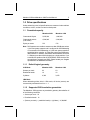
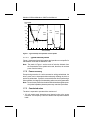
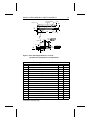
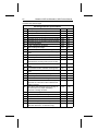
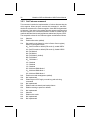
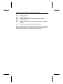
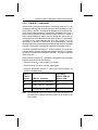
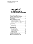
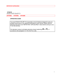
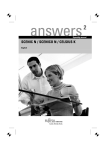
..................................... Marathon 2250 ..................................... Marathon 1680 ..................................... ATA Interface Drives ..................................... ..................................... Product Manual ..................................... ..................................... Marathon 2250 (ST92255AG) ..................................... Marathon 1680 (ST91685AG) ..................................... ATA Interface Drives ..................................... ..................................... Product Manual ..................................... 1997 Seagate Technology, Inc. All rights reserved Publication Number: 36337-101, Rev. B, March 1997 Seagate, Seagate Technology and the Seagate logo are registered trademarks of Seagate Technology, Inc. Marathon and SafeRite are trademarks of Seagate Technology. Other product names are registered trademarks or trademarks of their owners. Seagate reserves the right to change, without notice, product offerings or specifications. No part of this publication may be reproduced in any form without written permission from Seagate Technology, Inc. Marathon 2250 and Marathon 1680 Product Manual iii Contents Introduction . . . . . . . . . . . . . . . . . . . . . . . . . . . . 1 Specification summary table . . . . . . . . . . . . . . . . . . . 2 1.0 Drive specifications . . . . . . . . . . . . . . . . . . . . . . 5 1.1 Formatted capacity . . . . . . . . . . . . . . . . . . . . . 5 1.1.1 Default logical geometry . . . . . . . . . . . . . . . . 5 1.1.2 Supported CHS translation geometries . . . . . . . . 5 1.2 Physical organization . . . . . . . . . . . . . . . . . . . . 6 1.3 Recording and interface technology . . . . . . . . . . . . . 6 1.4 Physical characteristics . . . . . . . . . . . . . . . . . . . 7 1.5 Seek time . . . . . . . . . . . . . . . . . . . . . . . . . . 7 1.6 Start times . . . . . . . . . . . . . . . . . . . . . . . . . . 8 1.7 Power specifications . . . . . . . . . . . . . . . . . . . . . 8 1.7.1 Power consumption . . . . . . . . . . . . . . . . . . 8 1.7.2 Power recovery . . . . . . . . . . . . . . . . . . . . . 9 1.7.3 Conducted noise . . . . . . . . . . . . . . . . . . . . 9 1.7.4 Voltage tolerance . . . . . . . . . . . . . . . . . . . . 10 1.7.5 Power-management modes . . . . . . . . . . . . . . 10 1.8 Environmental tolerances . . . . . . . . . . . . . . . . . . 12 1.8.1 Ambient temperature . . . . . . . . . . . . . . . . . . 12 1.8.2 Temperature gradient . . . . . . . . . . . . . . . . . 12 1.8.3 Humidity . . . . . . . . . . . . . . . . . . . . . . . . 12 1.8.4 Altitude . . . . . . . . . . . . . . . . . . . . . . . . . 12 1.8.5 Shock . . . . . . . . . . . . . . . . . . . . . . . . . . 12 1.8.6 Vibration . . . . . . . . . . . . . . . . . . . . . . . . 13 1.9 Drive acoustics . . . . . . . . . . . . . . . . . . . . . . . 14 1.10 Reliability . . . . . . . . . . . . . . . . . . . . . . . . . . 14 1.11 Agency certification . . . . . . . . . . . . . . . . . . . . 15 1.11.1 Safety certification . . . . . . . . . . . . . . . . . . 15 iv Marathon 2250 and Marathon 1680 Product Manual 1.11.2 Electromagnetic Compatibility . . . . . . . . . . . . 15 1.11.3 FCC verification . . . . . . . . . . . . . . . . . . . . 15 2.0 Drive mounting and configuration . . . . . . . . . . . . . . 17 2.1 Handling and static-discharge precautions . . . . . . . . . 17 2.2 Jumper settings . . . . . . . . . . . . . . . . . . . . . . . 17 2.2.1 Master/slave configuration . . . . . . . . . . . . . . . 17 2.3 Remote LED configuration 2.4 Drive mounting . . . . . . . . . . . . . . . . . 19 . . . . . . . . . . . . . . . . . . . . . . . 19 2.5 ATA interface connector . . . . . . . . . . . . . . . . . . . 23 3.0 ATA Attachment-3 Interface (ATA-3) . . . . . . . . . . . . . 25 3.1 ATA interface signals and connector pins . . . . . . . . . . 25 3.1.1 AT bus signal levels . . . . . . . . . . . . . . . . . . 25 3.2 ATA Interface commands . . . . . . . . . . . . . . . . . . 27 3.2.1 Supported ATA commands . . . . . . . . . . . . . . . 27 3.2.2 Identify Drive command . . . . . . . . . . . . . . . . 29 3.2.3 Set Features command . . . . . . . . . . . . . . . . 32 3.2.4 S.M.A.R.T. commands . . . . . . . . . . . . . . . . . 34 3.2.5 Drive Security commands . . . . . . . . . . . . . . . 35 Appendix. Compatibility Notes . . . . . . . . . . . . . . . . . . 37 Marathon 2250 and Marathon 1680 Product Manual v Figures Figure 1. Typical startup and operation current profile. . . . . . . . 9 Figure 2. Connector and master/slave jumper setup . . . . . . . . 18 Figure 3. Drive mounting dimensions—side and bottom view. . . . 20 Figure 4. Drive mounting dimensions—end view . . . . . . . . . . 21 Figure 5. ATA Interface connector dimensions . . . . . . . . . . . 23 Figure 6. I/O pins and supported ATA signals . . . . . . . . . . . 26 vi Marathon 2250 and Marathon 1680 Product Manual Marathon 2250 and Marathon 1680 Product Manual 1 Introduction The Marathon 2250 (ST92255AG) and Marathon 1680 (ST91685AG) provide very high storage capacity in a small, 17-mm hard disc drive. Key Features: • Low power consumption • Compact, SFF-8200-compatible form-factor • High rotational speed for fast internal data transfer • Quiet operation • SafeRite shock protection • Support for PIO modes 0, 1, 2, 3 and 4, as well as single-word and multiword DMA modes 0, 1 and 2 • High instantaneous (burst) data-transfer rates (up to 16.6 Mbytes per second) using PIO mode 4 and DMA mode 2 • 103-Kbyte adaptive multisegmented cache • Fast caching and on-the-fly error-correction algorithms • Fast microprocessor for low command overhead • Support for S.M.A.R.T. drive monitoring and reporting • Support for drive password security • Support for Read/Write Multiple commands • Support for autodetection of master/slave drives using cable-select (CSEL) and DASP– signals 2 Marathon 2250 and Marathon 1680 Product Manual Specification summary table The specifications listed in this table are for quick reference. For details on a specification measurement or definition, see the appropriate section of this manual. Drive Specification Guaranteed Mbytes (1 Mbyte=106 bytes) Guaranteed sectors (LBA mode) Marathon 2250 Marathon 1680 2,250 1,680 4,394,940 3,282,490 Bytes per sector 512 Default sectors per track 63 63 Default read/write heads 16 16 4,360 3,256 10 8 5 4 Default cylinders Physical read/write heads Discs Recording density (bits/inch, max) 120,000 Track density (tracks/inch) 5,555 2 Areal density (Mbits/inch ) 666 Spindle speed (RPM) 4,508 Internal data-transfer rate (Mbits/sec max) 60.8 I/O data-transfer rate (Mbytes/sec max) 16.6 ATA data-transfer modes supported PIO modes 0, 1, 2, 3, 4 and multiword DMA modes 0, 1, 2 Cache buffer (Kbytes) 103 Height (mm max) 17.2 Width (mm max) 70.1 Length (mm max) 100.45 Weight (grams typical) Track-to-track seek time (msec typical) 204 200 4 (read), 5 (write) Average seek time (msec typical) 12 (read), 14 (write) Full-stroke seek time (msec max) 26 (read), 28 (write) Average latency (msec) 6.65 Marathon 2250 and Marathon 1680 Product Manual Drive Specification Power-on to ready (sec typical) Standby to ready (sec typical) Spinup current (peak) 3 Marathon 2250 Marathon 1680 3.5 2 1.3 amps Read/Write power and current (typical) 2.5 watts, 0.5 amps Seek power and current (typical) 2.5 watts, 0.5 amps Idle mode power and current (typical) 1.2 watts, 0.24 amps Standby mode power and current (typical) 0.3 watts, 0.06 amps Sleep mode power and current (typical) 0.1 watts, 0.02 amps Voltage tolerance (including noise) Ambient temperature (°C) Temperature gradient (°C per hour max) Relative humidity (operating) Wet bulb temperature (°C max) Altitude (meters above mean sea level, max) Shock, operating (Gs max) +5 volts, ± 5% 5 to 55 (op.), –40 to 70 (nonop.) 30 8% to 80% (10% per hour max grad.) 29.4 (op.), 40 (nonop.) –300 to 3,040 (op.), –300 to 12,190 (nonop.) 125 (2 msec) Shock, nonoperating (Gs max, 2 msec) 350 Vibration (Gs max at 5–400 Hz, without physical damage or loss of data) 0.75 (op.) 4.0 (nonop.) Drive acoustics (bels—sound power) Idle mode (dBA—sound pressure) 3.5 (typical), 3.8 (max) 24 (typical), 28 (max) Drive acoustics (bels—sound power ) Seek mode (dBA—sound pressure) 3.8 (typical), 4.1 (max) 26 (typical), 30 (max) Nonrecoverable read errors 1 per 1013 bits read Mean time between failures (power-on hours) 300,000 Contact start-stop cycles (40°C, ambient humidity) 50,000 Service life (years) 5 4 Marathon 2250 and Marathon 1680 Product Manual Marathon 2250 and Marathon 1680 Product Manual 5 1.0 Drive specifications Unless otherwise noted, all specifications are measured under ambient conditions, at 40°C, at sea level and nominal power. 1.1 Formatted capacity Marathon 2250 Marathon 1680 Guaranteed Kbytes 2,250,209 1,680,634 Guaranteed sectors (LBA mode) 4,394,940 3,282,490 Bytes per sector 512 512 Note. DOS systems are not able to access more than 528 Mbytes unless: 1) the host system supports and is configured for LBA addressing or for extended CHS addressing, or 2) the host system contains a specialized drive controller, or 3) the host system runs BIOS translation software. In addition, older BIOSs cannot address more than 2.1 Gbytes (more than 4,096 cylinders) on a single partition. If you encounter this problem with the ST92255AG, divide the drive into two partitions or upgrade your BIOS. Please contact your Seagate representative for additional information. 1.1.1 Default logical geometry CHS Mode Marathon 2250 Marathon 1680 Sectors per track 63 63 Read/write heads 16 16 Cylinders 4,360 3,256 LBA Mode When addressing either drive in LBA mode, all blocks (sectors) are consecutively numbered from 0 to n – 1. 1.1.2 Supported CHS translation geometries The Marathon 2250 supports any translation geometry that satisfies all of the following conditions: • Sectors per track ≤ 63 • Read/write heads ≤ 16 • (Sectors per track) × (read/write heads) × (cylinders) ≤ 4,394,880 6 Marathon 2250 and Marathon 1680 Product Manual The Marathon 1680 supports any translation geometry that satisfies all of the following conditions: • Sectors per track ≤ 63 • Read/write heads ≤ 16 • (Sectors per track) × (read/write heads) × (cylinders) ≤ 3,282,048 1.2 Physical organization Marathon 2250 Marathon 1680 Read/Write heads 10 8 Discs 5 4 1.3 Recording and interface technology Interface ATA Recording method 8/9 Recording density (bits/inch) 120,000 Track density (tracks/inch) 5,555 Areal density (Mbits/inch2) 666 Spindle speed (RPM) ( ± 0.5%) 4,508 Internal data-transfer rate (Mbits per sec max—ZBR) 60.8 I/O data-transfer rate (Mbytes per sec max) 16.6 (PIO mode 4 with IORDY) 16.6 (multiword DMA mode 2) Interleave 1:1 Cache buffer (Kbytes) 103 Marathon 2250 and Marathon 1680 Product Manual 7 1.4 Physical characteristics Marathon 2250 Marathon 1680 Maximum height (inches) (mm) 0.676 (17.2) 0.676 (17.2) Maximum width (inches) (mm) 2.76 (70.1) 2.76 (70.1) Maximum length (inches) (mm) 3.955 (100.45) 3.955 (100.45) Typical weight (ounces) (grams) 7.19 (204) 7.05 (200) Note. Maximum length excludes I/O connector pins that may extend up to 0.015 inches beyond the edge of the head/disc assembly, per SFF 8004 specification. 1.5 Seek time All seek times are measured using a 25 MHz 486 AT computer (or faster) with a 8.3 MHz I/O bus. The measurements are taken with nominal power at sea level and 40°C ambient temperature. The specifications in the table below are defined as follows: • Track-to-track seek time is an average of all possible single-track seeks in both directions. • Average seek time is a true statistical random average of at least 5,000 measurements of seeks between random tracks, less overhead. • Full-stroke seek time is one-half the time needed to seek from the first data cylinder to the maximum data cylinder and back to the first data cylinder. The full-stroke typical value is determined by averaging 100 full-stroke seeks in both directions. Seek type Typical read (msec) Typical write (msec) Track-to-track 4 5 Average 12 14 Full-stroke 26 28 Average latency: 6.65 msec 8 Marathon 2250 and Marathon 1680 Product Manual 1.6 Start times Power-on to Ready (sec) 3.5 typical, 7 max Standby to Ready (sec) 2 typical, 3 max Idle to Ready (sec) 0.4 max 1.7 Power specifications The drive receives DC power (+5V) through pin 41 and pin 42 of the AT interface connector. 1.7.1 Power consumption Power requirements for the drive are listed in the table below. Typical power measurements are based on an average of drives tested under nominal conditions, using 5.0V input voltage at 40°C ambient temperature at sea level. Active mode current and power are measured with a 32-msec delay between each operation and the drive in default logical geometry. Seeking power and currents are measured during one-third-stroke buffered seeks. Read/write power and current are measured with the heads on track, based on a 16-sector write followed by a 32-msec delay, then a 16-sector read followed by a 32-msec delay. Spinup power is measured from time of power-on to time of drive-ready for normal operation. The average peak represents peak power that is drawn from the battery. Mode Watts (at nominal voltage) Amps (at nominal voltage) Max Typical Max Spinup Peak (see Figure 1) — Average 4.0 — — 0.8 1.3 — Active Read/Write Seeking 2.5 2.5 2.6 2.6 0.5 0.5 0.52 0.52 Idle 1.2 1.3 0.24 0.26 Standby 0.3 0.36 0.06 0.072 Sleep 0.1 0.1 0.02 0.02 Typical Marathon 2250 and Marathon 1680 Product Manual 9 Current (mA) 1,400 Drive ready 1,200 1,000 Upload code Idle mode Active mode 800 Standby mode Sleep mode 600 400 Spinup 200 0 0 1 2 3 4 5 5 6 7 8 9 10 11 12 Time (seconds) Figure 1. Typical startup and operation current profile 1.7.1.1 Typical current profile Figure 1 shows a projected drive startup and operation current profile for the Marathon 2250 and the Marathon 1680. Note. The peaks in Figure 1 are the result of inductive kickback from the commutation of the spindle motor and, therefore, do not draw power from the battery. 1.7.2 Power recovery Except during execution of a write command or writing cached data, the drive’s power can be interrupted without adversely affecting the drive or previously written data. If power is removed while the drive is performing a write operation, the integrity of the data being written cannot be guaranteed. Note. Do not remove power from the drive while the interface signals are active (at low impedance) because power may enter the input buffers. 1.7.3 Conducted noise The drive is expected to operate with a maximum of: • 150 mV peak-to-peak triangular-wave injected noise at the power connector. The frequency is 10 Hz to 100 KHz with equivalent resistive loads. 10 Marathon 2250 and Marathon 1680 Product Manual • 100 mV peak-to-peak triangular-wave injected noise at the power connector. The frequency is 100 KHz to 10 MHz with equivalent resistive loads. Note. Equivalent resistance (9.26 ohms) is calculated by dividing the nominal voltage (5V) by the typical RMS read/write current (0.54 amps). 1.7.4 Voltage tolerance Voltage tolerance (including noise): +5 volts, ± 5% 1.7.5 Power-management modes Seagate’s Marathon drives provide programmable power management to enhance battery life and to provide greater energy efficiency. In most computers, you can control power management through the system setup program. These drives feature several power-management modes, which are summarized in the following table and are described in more detail below: Mode Heads Spindle Buffer Active Moving Rotating Enabled Idle Varies Rotating Enabled Standby Parked Stopped Enabled Sleep Parked Stopped Disabled Active mode. The drive is in Active mode during the read/write and seek operations. Idle mode. At power-on, the drive sets the Idle Timer to enter Idle mode after 5 seconds of inactivity. The drive remains in Idle mode with heads flying over the media for 15 minutes; then the drive makes the transition to Active mode and seeks to the last-known logical block address, where it remains for 5 minutes. The drive then seeks to a new, unspecified location two more times, for 5 minutes each, after which it makes the transition to Standby mode. In Idle mode, the spindle remains up to speed, the buffer remains enabled, and the drive accepts all commands and returns to Active mode whenever a disc access command is received. The drive enters Idle mode when an Idle or Idle Immediate command is received. The Idle or Idle Immediate command overrides the algorithm described above. The drive remains in Idle mode until a disc access command is received or the standby timer expires, whichever occurs first. Marathon 2250 and Marathon 1680 Product Manual 11 When the standby timer expires, the drive makes the transition to the Standby mode. The drive requires approximately 100–200 msec to return to Active mode from Idle mode. Standby mode. The drive enters Standby mode when the host sends a Standby or Standby Immediate command. If the standby command has set the standby timer, the drive enters Standby mode automatically after the drive has been inactive for the specified length of time. In Standby mode, the buffer remains enabled, the heads are parked and the spindle is at rest. The drive accepts all commands and returns to Active mode any time a disc access command is received. The drive requires approximately 3 seconds to return to Active mode from Standby mode. Sleep mode. The drive enters Sleep mode only after receiving a Sleep command from the host. The heads are parked and the spindle is at rest. The ROM and RAM codes are valid; however, the cache is flushed before going to sleep. The drive leaves Sleep mode when either a Hard Reset interface signal or a Soft Reset signal (Device Control register=04) is received from the host. After receiving a Soft Reset, the drive exits Sleep mode and enters Standby mode, with all current emulation and translation parameters intact. After receiving a Hard Reset signal, the drive exits Sleep mode and enters Active mode. The drive is reinitialized to the default parameters. This is the same procedure as initial power-on and requires approximately 7 seconds to complete. Idle and standby timers. The drive sets the default time delay for the idle timer at power-on to 5 seconds. If the idle timer reaches zero before any drive activity is required, the drive makes a transition to Idle mode. Each time the drive performs an Active function (read, write or seek), the idle and standby timers are reinitialized and begin counting down from their specified delay times to zero. If the standby timer has been set and no additional drive activity occurs, the drive remains in Idle mode for the time specified in the standby timer, then enters Standby mode. If the host has not set the standby timer and no additional drive activity occurs, the drive remains in Idle mode for 30 minutes, then enters standby mode. In both Idle and Standby mode, the drive accepts all commands and returns to Active mode when disc access is necessary. 12 Marathon 2250 and Marathon 1680 Product Manual 1.8 Environmental tolerances 1.8.1 Ambient temperature Operating 5° to 55°C (41° to 131°F) Nonoperating –40° to 70°C (–40° to 158°F) Caution. This drive needs sufficient airflow so that the maximum surface temperature at the center of the top cover of the drive does not exceed 62 degrees C (144 degrees F). 1.8.2 Temperature gradient Operating 30°C/hr (86°F/hr) max, without condensation Nonoperating 30°C/hr (86°F/hr) max, without condensation 1.8.3 Humidity 1.8.3.1 Relative humidity Operating 8% to 80% noncondensing (10% per hour max) Storage 8% to 90% noncondensing (10% per hour max) Transit 5% to 95% noncondensing (10% per hour max) 1.8.3.2 Wet bulb temperature Operating 29.4°C (85°F) max Nonoperating 40°C (104°F) max 1.8.4 Altitude Operating –300 m to 3,040 m (–1,000 ft to 10,000 ft) Nonoperating –300 m to 12,190 m (–1,000 ft to 40,000 ft) 1.8.5 Shock For shock specifications, it is assumed that the drive is mounted securely with the input levels at the drive mounting screws. For nonoperating specifications, it is assumed that the read/write heads are positioned in the shipping zone. Marathon 2250 and Marathon 1680 Product Manual 13 Note. At power-down, the read/write heads automatically move to the shipping zone. The head and slider assembly park inside of the maximum data cylinder. When power is applied, the heads recalibrate to Track 0. 1.8.5.1 Operating shock The Marathon 2250 and the Marathon 1680 incorporate SafeRite shock protection and can withstand a maximum operating shock of 125 Gs without nonrecoverable data errors (based on half-sine shock pulses of 2 msec). 1.8.5.2 Nonoperating shock The nonoperating shock level that the Marathon 2250 and Marathon 1680 can tolerate without incurring physical damage or degradation in performance is 350 Gs (based on half-sine shock pulses of 2 msec duration) or 150 Gs (based on half-sine shock pulses of 11 msec duration). Shock pulses are defined by MIL-STD-202 F with the amplitude tolerance controlled to ± 5%. 1.8.6 Vibration For vibration specifications, it is assumed that the drive is mounted in an approved orientation with the input levels at the drive mounting screws. For the nonoperating specifications, it is assumed that the read/write heads are positioned in the shipping zone. 1.8.6.1 Operating vibration The following table lists the maximum vibration levels that the drive may experience without incurring physical damage, data loss or performance degradation. 5–22 Hz 0.02-inch displacement (peak-to-peak) 22–400 Hz 0.75 Gs acceleration (0 to peak) 400–22 Hz 0.75 Gs acceleration (0 to peak) 22–5 Hz 0.02-inch displacement (peak-to-peak) 14 1.8.6.2 Marathon 2250 and Marathon 1680 Product Manual Nonoperating vibration The following table lists the maximum nonoperating vibration that the drive may experience without incurring physical damage or degradation in performance. 5–22 Hz 0.2-inch displacement (peak-to-peak) 22–400 Hz 4 Gs acceleration (0 to peak) 400–22 Hz 4 Gs acceleration (0 to peak) 22–5 Hz 0.2-inch displacement (peak-to-peak) 1.9 Drive acoustics Drive acoustics are measured as sound power, using techniques that are generally consistent with ISO document 7779. Measurements are taken under essentially free-field conditions over a reflecting plane, using a total of nine microphones that measure in the 250–4,000 Hz band. This methodology determines broad-band and narrow-band noise, and discrete frequency components. For all tests, the drive is oriented with the cover facing upward. Mode Typical Maximum Idle (sound power-bels) 3.5 3.8 Seek (sound power-bels) 3.8 4.1 Idle (sound pressure-dBA) 24 28 Seek (sound pressure-dBA) 26 30 1.10 Reliability Nonrecoverable read errors 1 per 1013 bits read Mean time between failures (MTBF) 300,000 power-on hours (nominal power, at sea level and 40°C ambient temperature) Contact start-stop cycles (CSS) 50,000 cycles (at nominal voltage and 40°C, with 60 cycles per hour and a 50% duty cycle) Preventive maintenance None required Service life 5 years Marathon 2250 and Marathon 1680 Product Manual 15 1.11 Agency certification 1.11.1 Safety certification The drive is recognized in accordance with UL 1950 and CSA C22.2 (950-M89) and meets all applicable sections of IEC 380, IEC 435, IEC 950, VDE 0806/08.81 and EN 60950 as tested by TUV-Rheinland, North America. 1.11.2 Electromagnetic Compatibility Hard drives that display the CE marking comply with European Union requirements specified in Electromagnetic Compatibility Directive 89/336/EEC as amended by Directive 92/31/EEC of 28 April 1992 and Directive 93/68/EEC of 22 July 1993. Seagate uses an independent laboratory to confirm compliance with the EC directives specified in the previous paragraph. Drives are tested in representative end-user systems using 80486, Pentium and PowerPC microprocessors. Although CE-marked Seagate drives comply with the directives when used in the test systems, we cannot guarantee that all systems will comply with the directives. The drive is designed for operation inside a properly designed enclosure, with properly shielded I/O cable (if necessary) and terminators on all unused I/O ports. The computer manufacturer or system integrator should confirm EMC compliance and provide CE marking for their products. 1.11.3 FCC verification These drives are intended to be contained solely within a personal computer or similar enclosure, not attached as an external device. As such, each drive is considered to be a subassembly even when it is sold individually to the customer. As a subassembly, no Federal Communications Commission verification or certification of the device is required. Seagate Technology, Inc. has tested this device in enclosures as described above to ensure that the total assembly (enclosure, disc drive, motherboard, power supply, etc.) complies with the limits for a Class B computing device, pursuant to Subpart J, Part 15 of the FCC rules. Operation with noncertified assemblies is likely to result in interference with radio and television reception. Radio and Television Interference. This equipment generates and uses radio frequency energy and, if not installed and used in strict accordance with the manufacturer’s instructions, may cause interference with radio and television reception. 16 Marathon 2250 and Marathon 1680 Product Manual This equipment is designed to provide reasonable protection against such interference in a residential installation. However, there is no guarantee that interference will not occur in a particular installation. If this equipment does cause interference with radio or television reception (which can be determined by turning the equipment on and off), try one or more of the following corrective measures: • Reorient the receiving antenna. • Move the device to one side or the other of the radio or TV. • Move the device farther away from the radio or TV. • Plug the computer into a different outlet so that the receiver and computer are on different branch outlets. If necessary, you should consult your dealer or an experienced radio or television technician for additional suggestions. You may find the following booklet from the Federal Communications Commission helpful: How to Identify and Resolve Radio-Television Interference Problems. This booklet is available from the Superintendent of Documents, U.S. Government Printing Office, Washington, DC 20402. Refer to publication number 004-000-00345-4. Marathon 2250 and Marathon 1680 Product Manual 17 2.0 Drive mounting and configuration 2.1 Handling and static-discharge precautions After unpacking, but before installation, the drive may be exposed to potential handling and ESD hazards. You must observe standard staticdischarge precautions. A grounded wrist-strap is recommended. Handle the drive only by the sides of the head/disc assembly. Avoid contact with the printed circuit board, all electronic components and the interface connector. Do not apply pressure to the top cover. Always rest the drive on a padded antistatic surface until you mount it in the host system. 2.2 Jumper settings 2.2.1 Master/slave configuration You must establish a master/slave relationship between two drives that are attached to a single AT bus. You can configure a drive to become a master or slave by setting the master/slave jumpers, as described below and shown in Figure 2 on page 18. Alternatively, you can configure the drive as a master or slave using the cable-select option. This requires a special daisy-chain cable that grounds pin 28 (CSEL) on one of its two drive connectors. If you attach the drive to the grounded CSEL connector, it becomes a master. If you attach the drive to the ungrounded CSEL connector, it becomes a slave. To use this option, the host system and both drives must support cableselect and both drives must be configured for cable-select. To configure Marathon drives for cable-select, install both master/slave jumpers. For the host to recognize the slave drive using the DASP– signal, the slave drive must assert the DASP– signal at power-up, and the master drive must monitor DASP– at power-up. 18 Marathon 2250 and Marathon 1680 Product Manual Note. Drive is shown with circuit board up. Master/slave Pin 1 configuration jumpers Pin 20 removed for keying Circuit board B A D C Drive is master; slave may be detected using DASP– signal Drive is master; Seagate slave drive present Drive is slave; Seagate master drive present Use CSEL pin grounding to differentiate master from slave Figure 2. Connector and master/slave jumper setup Jumper for pins A and B Jumper for pins C and D Off Off Drive is master; slave drive may be detected using DASP– signal. CSEL is ignored. Off On Drive is master; slave drive is present. CSEL is ignored. DASP– is ignored. On Off Drive is slave (a master drive should be present also). CSEL is ignored. On On Differentiate master and slave drives using cable-select: If a drive is attached to a connector in which pin 28 is grounded, then it becomes a master. If a drive is attached to a connector in which pin 28 is ungrounded, then it becomes a slave. Configuration Marathon 2250 and Marathon 1680 Product Manual 19 2.3 Remote LED configuration The drive indicates activity to the host through the DASP– line (pin 39) on the ATA interface. This line may be connected to a drive status indicator driving an LED at 5V. The line has a 30 mA nominal current limit; however, most external LEDs are sufficiently bright at 15 mA. Because the LED drops 1.7 volts, we recommend that you place a 200-ohm resistor in series with the LED to limit the current to 15 mA. 2.4 Drive mounting You can mount the drive in any orientation using four screws in the four side-mounting or four bottom-mounting holes. Allow a minimum clearance of 0.030 inches (0.76 mm) for cooling around the entire perimeter of the drive. The drive conforms to the industry-standard SFF-8200 mounting specifications and requires the use of SFF-8200-compatible connectors in direct-mounting applications. See Figures 3 and 4 on pages 20 and 21 for drive mounting dimensions. Note. Per SFF 8004 specifications, the I/O connector pins may extend up to 0.015 inches beyond the edge of the head/disc assembly. Caution. This drive needs sufficient airflow so that the maximum surface temperature at the center of the top cover of the drive does not exceed 62°C (144°F). Caution. To avoid damaging the drive, use M3X0.5 metric mounting screws only. Do not insert mounting screws more than 0.150 inches (3.81 mm) into the mounting holes. Do not overtighten the screws (maximum torque: 3 inch-lb). 20 Marathon 2250 and Marathon 1680 Product Manual A40 A39 S1 (to tips of I/O connector pins) A6 (to end of HDA) A1 +A2 –A3 A25 A24 A23 Z A37 X2 A37 X1 A21 ± A22 Y A26 thread, 4PLC min A38 full thread center within A27 of position specified A31 A30 A28 A7 A37 Z1 A37 Z2 A4 ± A5 (width at mounting holes) A32 thread, 4PLC min A41 full thread center within A33 of position specified A37 Z4 X A29 A37 Z3 A8 z x y Figure 3. Drive mounting dimensions—side and bottom view (for dimension specifications, see table on pages 21 and 22). Marathon 2250 and Marathon 1680 Product Manual Pin 20 removed for keying Pin 44 21 Pin 1 A34 Z A35 A1 +A2 –A3 A36 X A12 Detail A13 ± A14 A19 M z x A20 M A11 A9 A17 ± A18 Z A15 M z x A16 M A10 ± A10.1 X Figure 4. Drive mounting dimensions—end view (for dimension specifications, see table below). Mounting dimension specifications Dim. A1 A2 A3 A4 A5 A6 A7 A8 A9 A10 A10.1 A11 A12 A13 A14 A15 Description Drive height + tolerance on drive height – tolerance on drive height Drive width at mounting holes + and – tolerance on drive width at mounting holes Maximum drive length (not including I/O pins) Front-to-back connector location Allowable range, front-to-back connector location Top-to-bottom connector location, pin center line Side-to-side connector location, pin center line + and – tolerance, side-to-side connector location Top-to-bottom pin spacing Side-to-side pin spacing Pin side-to-side dimension + and – tolerance on pin side-to-side dimension Allowable range, side-to-side connector location continued on following page inches 0.668 0.008 0.008 2.750 0.009 3.955 0.403 0.039 0.157 0.399 0.015 0.079 0.079 0.020 0.002 0.030 mm 16.97 0.20 0.20 69.85 0.23 100.45 10.2 1.00 3.99 10.14 0.38 2.00 2.00 0.50 0.05 0.75 22 Marathon 2250 and Marathon 1680 Product Manual continued from previous page Mounting dimension specifications Dim. A16 A17 A18 A19 A20 A21 A22 A23 A24 A25 A26 A27 A28 A29 A30 A31 A32 A33 A34 A35 A36 A37 A38 A39 A40 A41 S1 Description Allowable range, side-to-side, pins within connector Pin top-to-bottom dimension + and – tolerance on pin top-to-bottom dimension Allowable range, top-to-bottom connector location Allowable range, top-to-bottom, pins in connector Connector pin length + and – tolerance on pin length Side mounting hole height Front-to-back location of side mounting holes Front-to-back distance between side mounting holes Thread description, side mounting holes Diam. of cylinder into which hole center must fall Distance between side of drive and center of nearest bottom mounting holes (on pin-44 side) Side-to-side distance between bottom mounting holes Front-to-back location of bottom mounting holes Front-to-back distance between bottom mounting holes Thread description, bottom mounting holes Diam. of cylinder into which hole center must fall Min. vertical clearance for mating connector Max. side-to-side distance from pin-44 edge of HDA near I/O connector to start of clearance for mating connector Min. side-to-side clearance from pin-44 edge of I/O connector to any object interrupting clearance of mating connector Diam. of datum targets and reference areas Min. thread depth, side mounting holes Min. pin centerline to chamfer above connector Min. chamfer above connector Min. thread depth, bottom mounting holes Maximum drive length to tips of I/O pins (Non-SFF dimension—for reference only) inches 0.003 0.020 0.002 0.020 0.003 0.152 0.008 0.118 0.551 3.016 mm 0.08 0.50 0.05 0.50 0.08 3.86 0.20 3.00 14.0 76.6 n/a 0.020 0.160 M3 0.50 4.06 2.430 61.72 0.551 3.016 14.0 76.6 n/a 0.020 0.039 0.315 M3 0.50 1.00 8.00 2.370 60.20 0.315 0.118 0.049 0.010 0.098 3.970 8.00 3.00 1.25 0.25 2.50 100.84 Marathon 2250 and Marathon 1680 Product Manual 23 2.5 ATA interface connector The drive connector is a 44-conductor connector with 2 rows of 22 male pins on 0.079-inch (2 mm) centers (see Figure 4 on page 21 and Figure 5). The mating cable connector is a 44-conductor, nonshielded connector with 2 rows of 22 female contacts on 0.079-inch (2 mm) centers. The connectors should provide strain relief and should be keyed with a plug in place of pin 20. These drives are designed to support the industry-standard SFF-8200 mounting specifications. When installing these drives in fixed mounting applications, use only SFF-compatible connectors such as Molex part number 87368-442x. For applications that involve flexible cables or printed circuit cables (PCCs), use Molex part number 87259-4413 or equivalent to connect the drive to the system. Select a connector that provides adequate clearance for the master/slave configuration jumpers if the application requires the use of such jumpers. The ATA interface cable should be no more than 18 inches long. Note. Per SFF 8004 specifications, the I/O connector pins may extend up to 0.015 inches beyond the edge of the head/disc assembly. Master/slave jumpers 1.654 (42.01) 0.158 ± 0.003 (4.00 ± 0.08) Dimensions are in inches (mm) Figure 5. ATA Interface connector dimensions (non-SFF dimension, for reference only) 24 Marathon 2250 and Marathon 1680 Product Manual Marathon 2250 and Marathon 1680 Product Manual 25 3.0 ATA Attachment-3 Interface (ATA-3) The drives in this manual comply with the ATA-3 Standard, proposed by the X3T10 committee, a Technical Committee of Accredited Standards Committee X3, of the American National Standards Institute (ANSI). The X3T10 committee has been renamed to X3T13 to reflect its current standards work. For more information about the committee and the standards, see the committee’s Internet FTP site: ftp://fission.dt.wdc.com/pub/standards/X3T13T 3.1 ATA interface signals and connector pins Figure 6 on page 26 summarizes the signals on the ATA interface connector that the drive supports. For a detailed description of these signals, refer to the Working Draft of the Proposed American National Standard X3T10/2008D Revision 6, Information Technology AT Attachment-3 Interface (ATA-3), subsequently referred to as the Draft Proposed ATA-3 Standard. 3.1.1 AT bus signal levels Signals that the drive sends have the following output characteristics at the drive connector: Logic Low 0.0V to 0.4V Logic High 2.5V to 5.25V Signals that the drive receives must have the following input characteristics, measured at the drive connector: Logic Low 0.0V to 0.8V Logic High 2.0V to 5.25V 26 Marathon 2250 and Marathon 1680 Product Manual Drive pin # 1 2 3 4 5 6 7 8 9 10 11 12 13 14 15 16 17 18 19 20 21 22 23 24 25 26 27 28 29 30 31 32 33 34 35 36 37 38 39 40 41 42 43 44 Signal name Reset– Ground DD7 DD8 DD6 DD9 DD5 DD10 DD4 DD11 DD3 DD12 DD2 DD13 DD1 DD14 DD0 DD15 Ground (removed) DMARQ Ground DIOW– Ground DIOR– Ground IORDY CSEL DMACK– Ground INTRQ IOCS16– DA1 PDIAG– DA0 DA2 CS1FX– CS3FX– DASP– Ground Power Power Ground Reserved Host pin # and signal description 1 2 3 4 5 6 7 8 9 10 11 12 13 14 15 16 17 18 19 20 21 22 23 24 25 26 27 28 29 30 31 32 33 34 35 36 37 38 39 40 41 42 43 44 Host Reset Ground Host Data Bus Bit 7 Host Data Bus Bit 8 Host Data Bus Bit 6 Host Data Bus Bit 9 Host Data Bus Bit 5 Host Data Bus Bit 10 Host Data Bus Bit 4 Host Data Bus Bit 11 Host Data Bus Bit 3 Host Data Bus Bit 12 Host Data Bus Bit 2 Host Data Bus Bit 13 Host Data Bus Bit 1 Host Data Bus Bit 14 Host Data Bus Bit 0 Host Data Bus Bit 15 Ground (No Pin) DMA Request Ground Host I/O Write Ground Host I/O Read Ground I/O Channel Ready Cable Select pin DMA Acknowledge Ground Host Interrupt Request Host 16 Bit I/O Host Address Bus Bit 1 Passed Diagnostics Host Address Bus Bit 0 Host Address Bus Bit 2 Host Chip Select 0 Host Chip Select 1 Drive Active / Slave Present Ground +5 volts DC (logic) +5 volts DC (motor) Ground for power pins Reserved Pins 28, 34 and 39 are used for master-slave communication (details shown below). Drive 1 (slave) 28 34 39 Drive 0 (master) 28 34 39 CSEL PDIAG– DASP– Figure 6. I/O pins and supported ATA signals Host 28 34 39 Marathon 2250 and Marathon 1680 Product Manual 27 3.2 ATA Interface commands 3.2.1 Supported ATA commands The following table lists supported ATA-standard and Seagate-specific drive commands. For a detailed description of the ATA commands, refer to the Draft Proposed ATA-3 Standard. See Section 3.2.4 on page 33 for details and subcommands used in the S.M.A.R.T. implementation. Command name Command code Supported by Marathon 2250 and Marathon 1680 ATA-standard commands Execute Drive Diagnostics 90H Yes Format Track 50H Yes Identify Drive ECH Yes Initialize Drive Parameters 91H Yes NOP 00H No Read Buffer E4H Yes Read DMA (w/retry) C8H Yes Read DMA (no retry) C9H Yes Read Long (w/retry) 22H Yes Read Long (no retry) 23H Yes Read Multiple C4H Yes Read Sectors (w/retry) 20H Yes Read Sectors (no retry) 21H Yes Read Verify Sectors (w/retry) 40H Yes Read Verify Sectors (no retry) 41H Yes Recalibrate 10H Yes Seek 70H Yes Set Features EFH Yes Set Multiple Mode C6H Yes continued on following page 28 Marathon 2250 and Marathon 1680 Product Manual continued from previous page Command name Command code Supported by Marathon 2250 and Marathon 1680 Execute S.M.A.R.T Command B0H Yes Write Buffer E8H Yes Write DMA (w/retry) CAH Yes Write DMA (no retry) CBH Yes Write Long (w/retry) 32H Yes Write Long (no retry) 33H Yes Write Multiple C5H Yes Write Same E9H No Write Sectors (w/retry) 30H Yes Write Sectors (no retry) 31H Yes Write Verify 3CH No Drive Security Commands Security Set Password F1H Yes Security Unlock F2H Yes Security Erase Prepare F3H Yes Security Erase Unit F4H Yes Security Freeze Lock F5H Yes Security Disable Password F6H Yes ATA-standard power-management commands Check Power Mode 98H or E5H Yes Idle 97H or E3H Yes Idle Immediate 95H or E1H Yes Sleep 99H or E6H Yes Standby 96H or E2H Yes Standby Immediate 94H or E0H Yes Marathon 2250 and Marathon 1680 Product Manual 29 The following commands contain drive-specific features that may not be described in the Draft Proposed ATA-3 Standard. 3.2.2 Identify Drive command The Identify Drive command (command code ECH) transfers information about the drive to the host following power-up. The data is organized as a single 512-byte block of data, the contents of which are shown in the table below. All reserved bits or words should be set to zero. Parameters listed with an “x” are drive-specific or vary with the state of the drive. See Section 1 of this manual for default parameter settings for the Marathon 2250 and the Marathon 1680. Word Description Contents 0 Configuration information: Bit 6: fixed drive 1 Number of fixed cylinders (default logical emulation): 4,360 (ST92255AG); 3,256 (ST91685AG) 2 ATA-reserved 0000H 3 Number of heads (default logical emulation): 16 0010H 4 ATA-obsolete 0000H 5 ATA-obsolete 0000H 6 Number of sectors per track (default logical emulation): 63 003FH Not used by this drive 0000H Serial number: (20 ASCII characters, 0000H = none) ASCII 20 ATA-obsolete 0000H 21 ATA-obsolete 0000H 22 Number of ECC bytes available (16) 0010H Firmware revision (8 ASCII character string): 23–26 xx = ROM version, ss = RAM version, tt= RAM version xx.ss.tt 7–9 10–19 continued on following page 0040H 1108H (ST92255AG) 0CB8H (ST91685AG) 30 Marathon 2250 and Marathon 1680 Product Manual continued from previous page Word Description Contents ST92255AG or ST91685AG 27–46 Drive model number: (40 ASCII characters, padded with blanks to end of string) 47 Maximum sectors per interrupt on read/write multiple 0010H 48 Double word I/O (not supported) 0000H 49 Standby timer values supported per ATA standard, IORDY supported, IORDY can be disabled 2C00H 50 ATA-reserved 0000H 51 PIO data-transfer cycle timing mode 0200H 52 DMA transfer cycle timing mode (not used) 0000H 53 Validity of words 54–58 and words 64–70 (words may be valid) 0003H 54 Number of cylinders (current emulation mode) xxxxH 55 Number of heads (current emulation mode) xxxxH 56 Number of sectors per track (current emulation mode) xxxxH 57–58 Number of sectors (current emulation mode) 59 Number of sectors transferred during a Read Multiple or Write Multiple command xxxxH 01xxH (ST92255AG) 0FBC 0043H 60–61 LBA sectors available (ST91685AG) 017FC 0032H 62 ATA obsolete 0000H 63 Multiword DMA active/modes supported (see note following) 0x07H 64 Advanced PIO modes supported (modes 3 and 4 supported) 0003H Marathon 2250 and Marathon 1680 Product Manual Word Description 31 Contents 65 Minimum multiword DMA transfer cycle time per word (120 nsec) 0078H 66 Recommended multiword DMA transfer cycle time per word (180 nsec) 0078H 67 Minimum PIO cycle time without IORDY flow control (363 nsec) 016BH 68 Minimum PIO cycle time with IORDY flow control (120 nsec) 0078H 69–127 ATA-reserved 0000H 128–159 Seagate-reserved xxxxH 160–255 ATA-reserved 0000H Note. The following DMA mode settings are used in word 63 of the Identify Drive command: Word Bit Description (if bit is set to 1) 63 0 Multiword DMA mode 0 available 63 1 Multiword DMA mode 1 available 63 2 Multiword DMA mode 2 available 63 8 Multiword DMA mode 0 currently active 63 9 Multiword DMA mode 1 currently active 63 10 Multiword DMA mode 2 currently active 32 3.2.3 Marathon 2250 and Marathon 1680 Product Manual Set Features command This command controls the implementation of various features that the drive supports. When the drive receives this command, it sets BSY, checks the contents of the Features register, clears BSY and generates an interrupt. If the value in the register does not represent a feature that the drive supports, the command is aborted. Power-on default has the read look-ahead and write caching features enabled and 4 bytes of ECC. The acceptable values for the Features register are defined as follows: 01H 02H 03H 04H 33H 44H 54H 55H 66H 77H 81H 82H 84H 88H Obsolete Enable write cache (default) Set transfer mode (based on value in Sector Count register) Sector Count register values: 00H Set PIO mode to default (PIO mode 2), enable IORDY 01H Set PIO mode to default (PIO mode 2), disable IORDY 08H PIO Mode 0 09H PIO Mode 1 0AH PIO Mode 2 (default) 0BH PIO Mode 3 0CH PIO Mode 4 10H Obsolete 11H Obsolete 12H Obsolete 20H Multiword DMA Mode 0 21H Multiword DMA Mode 1 22H Multiword DMA Mode 2 Enable auto-read reassignment (default) Not implemented Sixteen bytes of ECC apply on read long and write long commands Not implemented Disable read look-ahead (read cache) feature Disable reverting to power-on defaults Not implemented Obsolete Disable write cache Not implemented Not implemented Marathon 2250 and Marathon 1680 Product Manual 99H 9AH AAH ABH BBH CCH 33 Not implemented Not implemented Enable read look-ahead (read cache) feature (default) Not implemented 4 bytes of ECC apply on read long and write long commands (default) Enable reverting to power-on defaults (default) At power-on or after a hardware reset, the default values of the features are as indicated above. A software reset also changes the features to default values unless a 66H command has been received. 34 3.2.4 Marathon 2250 and Marathon 1680 Product Manual S.M.A.R.T. commands Self-Monitoring, Analysis and Reporting Technology (S.M.A.R.T.) is an emerging technology that provides near-term failure prediction for disc drives. When S.M.A.R.T. is enabled, the Seagate drive monitors predetermined drive attributes that are susceptible to degradation over time. If self-monitoring determines that a failure is likely, S.M.A.R.T. makes a status report available so that the host can prompt the user to back up data on the drive. Not all failures are predictable. S.M.A.R.T. predictability is limited to only those attributes the drive can monitor. For more information on S.M.A.R.T. commands and implementation, see the Working Draft of the Proposed American National Standard X3T10/2008D Revision 6, Information Technology AT Attachment-3 Interface (ATA-3). This drive is shipped with S.M.A.R.T. features disabled. You must have a recent BIOS or software package that supports S.M.A.R.T. to enable the feature. The table below shows the S.M.A.R.T. command codes that these drives use. Before executing a S.M.A.R.T. command by writing B0H to the Command Register, the host must do the following: • Write the value 4FH to the Cylinder_Low register. • Write the value C2H to the Cylinder_High register. • Write the appropriate S.M.A.R.T. code to the Features register, as shown in the table below: Code in Features Register S.M.A.R.T. Command Supported by Marathon 2250 and Marathon 1680 D8H Enable S.M.A.R.T. Operations Yes D9H Disable S.M.A.R.T. Operations Yes DAH Return S.M.A.R.T. Status Yes Note. If an appropriate code is not written to the Features Register, the command will be aborted and 0x04 (abort) will be written to the Error register. Marathon 2250 and Marathon 1680 Product Manual 3.2.5 35 Drive-Security commands The drive-security commands provide a password-based security system to prevent unauthorized access to a disc drive. During manufacturing, the master password, SEAGATE, is set for the drive, and the lock function is disabled. The system manufacturer or dealer may set a new master password using the Security Set Password command (F1H), without enabling the lock function. Before a user password is entered, the drive rejects all security commands except Security Set Password. When the user sets a password, the drive automatically enters lock mode (lock mode is enabled) the next time it is powered on. When lock mode is enabled, the drive rejects all media-access commands until the user enters the correct user password, completing a Security Unlock command. The drive supports two levels of security: high security and maximum security. In high-security mode, if you forget your password, you can still access the data by entering the master password. In maximum-security mode, if you forget your password, you cannot access the data. However, in maximum-security mode, you can erase all data on the drive and reinitialize the drive using the Erase Unit command (F4H). You must enter the master password to complete an Erase Unit command. The Freeze Lock command (F5H) prevents you from changing security features. If, during normal drive operation, the Freeze Lock command is executed, all normal drive commands are implemented, but the security commands Disable Password, Erase Unit, Set Password and Unlock cannot be completed. See the ATA-3 specification (Document X3T10/2008D) for additional details about the Drive Security Commands. 36 Marathon 2250 and Marathon 1680 Product Manual Marathon 2250 and Marathon 1680 Product Manual 37 Appendix. Compatibility notes ECC testing When a Marathon 2250 or Marathon 1680 performs hardware-based ECC error correction on-the-fly, the drive does not report an ECC error. This allows ECC correction without degrading drive performance. Some older drive diagnostic programs test ECC features by creating small data errors and then checking to see if they are reported. Such tests, when run on these drives, may incorrectly report an ECC detection failure because the drive hardware corrects the data automatically, avoiding the error rather than reporting it. Such a report does not indicate a drive malfunction. Seagate Technology, Inc. 920 Disc Drive, Scotts Valley, California 95066, USA Publication Number: 36337-101, Rev. B, Printed in USA