1
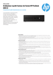
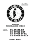
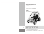
AFE325
AFE325 Product Manual
Purpose of this manual: To provide detailed
installation and operation instructions; to give
insights into how the machine works; to list
possible causes for problems; and to suggest
procedures for specific types of service.
The refrigeration system is either air or water
cooled, and it uses R-134a as a refrigerant. The
control system uses thermostat as a bin control
and a water pressure switch as the water safety
control.
The AFE325 is an ice maker that makes and
stores flaked ice.
Table of Contents
Specifications: . . . . . . . . . . . . . . . . . . . . . . . . . . . . . . . . . . . . . . . . . . . . Page 2
To The Installer: . . . . . . . . . . . . . . . . . . . . . . . . . . . . . . . . . . . . . . . . . . . Page 3
For The Plumber . . . . . . . . . . . . . . . . . . . . . . . . . . . . . . . . . . . . . . . . . . Page 4
For The Electrician . . . . . . . . . . . . . . . . . . . . . . . . . . . . . . . . . . . . . . . . . Page 5
Final Check List & Initial Start Up . . . . . . . . . . . . . . . . . . . . . . . . . . . . . . . . . . Page 6
User Operation . . . . . . . . . . . . . . . . . . . . . . . . . . . . . . . . . . . . . . . . . . . Page 7
Component Location: Control Box . . . . . . . . . . . . . . . . . . . . . . . . . . . . . . . . . Page 8
Refrigeration System Operation
. . . . . . . . . . . . . . . . . . . . . . . . . . . . . . . . . . Page 9
Water System Operation: . . . . . . . . . . . . . . . . . . . . . . . . . . . . . . . . . . . . . . Page 10
Mechanical Operation . . . . . . . . . . . . . . . . . . . . . . . . . . . . . . . . . . . . . . . . Page 11
Sanitation and Cleaning . . . . . . . . . . . . . . . . . . . . . . . . . . . . . . . . . . . . . . . Page 12
Maintenance And Cleaning . . . . . . . . . . . . . . . . . . . . . . . . . . . . . . . . . . . . . Page 13
Maintenance: Air Cooled Condenser . . . . . . . . . . . . . . . . . . . . . . . . . . . . . . . . Page 14
Maintenance: Component Inspection . . . . . . . . . . . . . . . . . . . . . . . . . . . . . . . . Page 15
Service Diagnosis . . . . . . . . . . . . . . . . . . . . . . . . . . . . . . . . . . . . . . . . . . Page 16
Removal and Replacement . . . . . . . . . . . . . . . . . . . . . . . . . . . . . . . . . . . . . Page 18
Water Seal & Bottom Bearing Replacement: . . . . . . . . . . . . . . . . . . . . . . . . . . . . Page 19
Refrigeration System . . . . . . . . . . . . . . . . . . . . . . . . . . . . . . . . . . . . . . . . Page 20
Gear Reducer Removal . . . . . . . . . . . . . . . . . . . . . . . . . . . . . . . . . . . . . . . Page 21
Gear Reducer Rebuild . . . . . . . . . . . . . . . . . . . . . . . . . . . . . . . . . . . . . . . Page 22
A Parts List and Wiring Diagram are located in the center of this manual, printed on yellow paper.
August 1994
Page 1
AFE325
Specifications:
Scotsman assumes no
liability or responsibility of
any kind for products
manufactured by
Scotsman that have been
altered in any way,
including the use of parts
and/of other components
not specifically approved
by Scotsman.
The finish for this machine is either
painted enamel or stainless steel. No
panel kit is available to convert an
enamel machine to stainless steel.
Scotsman ice machines, like the
AFE325, are designed to be installed
indoors, in a controlled environment.
The minimum and maximum
operating conditions are:
• Minimum Air Temperature:
50oF.
• Maximum Air Temperature:
100oF.
• Minimum Water Temperature:
40oF.
• Maximum Water Temperature:
100oF.
• 60 Hz Voltage may vary between
104 and 126 volts.
• Water Pressure may vary
between 20 and 80 psi.
Operating the machine
outside these
conditions constitutes
misuse and voids the
warranty.
Scotsman reserves the
right to make design
changes and/or
improvements at any
time. Specifications and
designs are subject to
change without notice
Scotsman Ice Systems
are designed and
manufactured with the
highest regard for
safety and
performance. They
meet or exceed the
standards of UL, NSF
and CSA.
.
Model
Dimensions
AFE325AE-1A 33 x 36 1⁄16 x 24
Basic
Electrical
115/60/1
Condenser
Type
Air Cooled
Min. Circ. Max. Fuse
Ampacity Size
10.7
15
Refrigerant Charge
(R-134a)
11 oz.
AFE325AE-6A 33 x 36 1⁄16 x 24
230/50/1
Air Cooled
5.4
11 oz.
H’ x W" x D"
August 1994
Page 2
15
AFE325
To The Installer:
A professional installation of any product is critical
to the long term satisfaction of the user. The
AFE325 is designed to be installed indoors, near a
drain. Determine the location from the anticipated
use and any options planned for.
This air cooled machine blows air out the back and
left sides of the cabinet. Do not install the machine
where the air flow might be blocked.
The machine will require electrical power, water
and a drain. Follow all local codes. Rough in the
utilities before placing the machine into position
(see For The Electrician and For The Plumber).
After uncrating, install the legs or optional casters.
If the building’s drain is a floor drain near the
machine, the cabinet can be placed on the floor
and sealed around the edges.
Place the cabinet in the place where it will be
operating. Note that the electrical and water
connections need to be made.
Water Quality:
The quality of the water supplied to the machine
will directly affect the purity of the ice and the
reliability of the machine. While the condition of the
water supplied to a building is normally out of the
control of the user, water can be treated at the
point of use.
There are two major types of water impurities:
suspended solids (those that are carried along
with the water and may be filtered out) and
dissolved solids (those that are part of the water
and have to be treated). A water filter is always a
good idea, but does require regular maintenance
to change the cartridge. In some water conditions,
water treatment may be required. Generally this
means a polyphosphate feeder of some kind.
Water softeners are not recommended for the
AFE325.
Level the unit front to back and left to right.
Nameplate Is Located
On The Back Panel.
Warm Air
Out
Utility
Connections
Here
Airflow Direction
Cool Air In
Warm Air Out
August 1994
Page 3
AFE325
For The Plumber
Drains: The ice maker requires a gravity drain for
the reservoir overflow and bin drain. The pitch on
the drain tubes must be at least 1/4 inch fall per
foot of horizontal run. On long horizontal runs, a
vent at the back of the cabinet will improve
draining, and is recommended.
There are two drains and one water inlet
connection to make.
Water supply:
Route a drain line to the reservoir overflow drain
hose. Route a separate drain to the bin drain tube.
Connect cold, potable water to the machine. A
hand valve near the location is recommended. A
water filter is also a good idea.
The drains are: a copper bin drain tube; and a
rubber reservoir overflow tube.
The water inlet connection is a 3/8" male flare.
Route the inlet water line to the fitting on the
corner post.
Follow all local codes.
Water Inlet
3/8" Male Flare
7⁄16"
Drain
I.D. Flexible Hose
January 2005
Page 4
AFE325
For The Electrician
Electrical connections:
Follow All Local, State & National Codes
Check the nameplate for voltage and current
requirements. An electrical cord is not supplied.
Connect the AFE325 to a separate electrical
circuit. Wiring to the machine must conform to all
codes. A licensed electrician may be required in
some situations. The electrical connection is made
in the control box inside the machine.
This unit must be grounded.
Route the electrical power cord thru the corner
post to the control box inside the cabinet.
Top Panel
To make the electrical connection, remove the
following parts:
• Top panel
• Bin door
• Rubber moulding
• Left moulding cover
• Left track
• Upper front panel
• Upper baffle
• Left side panel
• Front louvered panel
• Control box cover
If the machine will be started up later, after making
the electrical connections, replace all panels.
Control Box Cover
Ice Discharge Tube
(Ref)
Upper Front
Panel
Electrical
Inlet
Bin Door
Spacer
Bin Door
Serial Number
Plate
Left Track
Left Side
Panel
Left Moulding
Cover
Front Louvered
Panel
Upper Baffle
August 1994
Page 5
AFE325
Final Check List & Initial Start Up
1. Is the machine located indoors where the
temperature limitations are not exceeded?
Initial Start Up
2. Is there at least 6" clearance on the left side and
the back of the cabinet for adequate air flow?
3. Is the water supply adequate, and has a shut off
valve been installed?
4. Is the cabinet level?
5. Have all of the electrical and drain connections
been made?
Note: For High Altitude Installations an Altitude
Adjustment May Be Required:
(11-0354-01, 20 Ranco brand bin thermostats only)
Adjustment
Altitude (ft.
Amount of
above seal level) adjustment from
factory setting
Range
Screw CW
2,000
4,000
6,000
8,000
35o
90o
145o
190o
1. Remove the following parts:
• Top panel
• Bin door
• Rubber molding
• Left molding cover
• Left track
• Upper front panel
• Upper baffle
• Left side panel
• Front louvered panel
• Control box cover
• the top panel.
2. Open the water shut off valve.
3. Watch the water fill the reservoir. Check that it
flows in and fills the reservoir near to the mark
molded into the side of the reservoir. Check that
the float shuts off the water flow when the tank is
full. Check for leaks. Tighten hose clamps as
needed.
4. Plug the unit in or switch on the electrical power.
5. Switch the master switch to ON.
6. Let the machine operate, listen for any unusual
noises. If needed, reposition tubing & panels to
eliminate vibration.
After the unit has been operating for about 10
minutes, there should be enough ice in the bin to
test the bin thermostat.
7. Pick up some ice and hold it up against the
bottom of the ice thermostat tube.
8. After a short time the bin thermostat should
switch the machine off.
9. Pour water into the bin and check that the drain
does not leak but drains the water rapidly.
10. Replace all panels.
11. Explain to the user the maintenance
requirements and operation of the machine.
12. Fill out the Warranty Registration and
Customer Evaluation form. Mail it to Scotsman.
13. Leave the service manual with the owner/user
and explain who should be called if service is
needed.
August 1994
Page 6
AFE325
User Operation
The AFE325 is an automatic ice flaked machine.
All it requires is cool air, clean water, a drain, and
an adequate supply of electrical power.
The user must regularly sanitize and clean the
machine.
Component Location & Function
Evaporator. This is a vertical cylinder full of water
and refrigerated. Also in the cylinder is a slowly
rotating auger. The auger forces the ice up the
evaporator walls and compresses it at the top. The
resulting flaked ice then falls by gravity into the ice
storage bin.
Water Reservoir. The water reservoir contains the
inlet float valve and the water level sensor. The
float valve controls the flow of water into the
reservoir.
Water Pressure Cut Out Switch: The purpose of
this switch is to stop the ice maker if the water
supply fails.
Condenser. The AFE325 uses an air cooled
condenser. It blows air out, away from the fan
motor. The heat removed from the water is
exhausted from the condenser.
Compressor. The refrigeration system
compressor provides the force to move the
refrigerant around the system.
Auger Drive. The auger drive
is a direct drive gear reducer.
August 1994
Page 7
AFE325
Component Location: Control Box
Auger Delay Pressure Control: This pressure
switch, connected to the low side of the
refrigeration system, controls the auger drive
motor.
On-Off switch: This toggle switch shuts off the
machine. It is not a complete disconnect.
Bin Thermostat: This thermostat turns the
machine on and off in response to changes in
temperature of the capillary tube. It opens at 350 F.
and closes at 450 F. The capillary tube is mounted
on the inside of the ice chute.
Toggle Switch
Auger Delay Pressure
Control
Terminal Strip
Bin Thermostat
Control Box
August 1994
Page 8
AFE325
Refrigeration System Operation
The AFE325 uses a forced draft air cooled
condenser, capillary tube and hermetic
compressor. The system uses R-134a as a
refrigerant. High pressure, high temperature
refrigerant is forced thru the condenser where it
looses enough heat to condense. The high
pressure liquid refrigerant then passes thru the
capillary tube which causes a pressure drop in the
evaporator. As the high pressure liquid refrigerant
moves into the evaporator’s area of low pressure,
the warm water and low pressure cause the
refrigerant to evaporate and absorb heat from the
metal walls of the evaporator. After the refrigerant
has flowed thru the evaporator it goes back to the
compressor thru the suction line as a low pressure
vapor. At the compressor the cycle is repeated.
The AFE325 uses a low side pressure control as a
safety, it will shut the system down if the suction
pressure is too low for reliable operation.
System Characteristics:
Note: This ice machine has a sealed
refrigeration system. Tap into the system ONLY
when it’s absolutely necessary. After tapping
in, recovery, repair, evacuation and recharging,
the piercing valve must be removed and the
system re-sealed.
Typical Low Side Pressure*: 7 - 10 PSIG
Typical Discharge Side Pressure*: 130 - 165 PSIG
Typical Auger Drive Motor Amps (60 Hz): 2.8 - 3.1
Auger Drive Output RPM (60 Hz): 9.6
System Refrigerant Charge: 11 Ounces of R-134a
* Pressures depend upon air and water
temperatures. Numbers listed are for 70oF.
air/50oF. water and 90oF. air/70oF. water.
Refrigeration System Schematic
Evaporator
Capillary Tube
Suction Line
Drier
Compressor
Air Cooled
Condenser
August 1994
Page 9
AFE325
Water System Operation:
The water system consists of a float valve and
reservoir. The water level in the reservoir tank is
the same level as that inside the evaporator.
Building water supply flows to the float valve and
the float valve opens to add water to the reservoir
as water flows out to the evaporator.
.
Inside the evaporator there is a water seal. This
seal is the type that has a rotating half and a
stationary half. The area where the two seals
touch are smooth flat surfaces. When the auger is
installed in the evaporator, it forces the rotating
half of the seal against the stationary half. The
stationary half is spring-loaded and provides a firm
pressure against the auger portion of the seal.
Reservoir
Ice
Bin
Thermostat
Bracket
Clamp
Grommet
Ice Tube
Spout
Float
Water Inlet
Water Line
Evaporator
Reservoir Overflow
Gear Reducer
Bin Drain
Water System Schematic
August 1994
Page 10
AFE325
Mechanical Operation
• As the compressor runs, the low side or suction
ELECTRICAL SEQUENCE
There are two circuits in the AFE325: one is a
series circuit with several switches connected in
series to the compressor. The other is a parallel
branch of the series circuit, controlling the gear
drive motor.
• The series circuit begins at the terminal strip in
the control box. From there, the line side power
is connected to the Master Switch.
• When the master switch is closed, the power is
then connected to the Spout Switch. This
switch, located on the top of the ice chute, is
closed unless the ice chute has overfilled with
ice, it is a manual reset.
• The line side power is also connected, in a
parallel circuit, to terminal 1 of the Auger Delay
pressure control. This pressure control,
connected to the low side of the refrigeration
system, is designed as a by-pass circuit to the
auger drive motor whenever the low side
refrigerant pressure is at it’s normal ice making
range. At start up, the contacts between
terminals 1 and 2 are open. The line side power
does not pass any further through the auger
delay pressure control, until the compressor
starts, and the low side pressure drops.
• The next control the power is connected to is
the Low Water Pressure Control. This switch is
designed to open should the water pressure to
the machine drop too low.
• The next control is the Bin Thermostat. It is
closed when there is no ice on the portion of the
control inside the ice bin. It is open when there
is ice on the portion of the control inside the ice
bin. Closing of the bin thermostat begins the
process of making ice, because the line side
power now goes to the compressor, gearmotor,
and if air cooled, the fan motor.
• Power is initially connected to the gearmotor
through contacts 3 and 2 of the auger delay
pressure control. This causes the auger motor
to start and run. At the same time, if the
centrifugal switch on top of the gearmotor
closes (meaning the motor is at full speed) the
compressor is connected to the neutral side of
the power supply, and the compressor begins
to run.
pressure begins to fall, when it reaches a preset
point, the contacts within it move, opening 3
and 2, then closing 1 and 2. The power for the
gearmotor is then connected to a point in the
series circuit ahead of the low pressure control,
the low water pressure control and the bin
thermostat, so that if any of these open, the
gearmotor will continue to run, pushing ice out
of the evaporator.
The refrigeration system uses a hermetic
compressor (specifically designed for R-134a),
forced draft air cooled condenser, capillary tube
and vertical flaked ice evaporator. Inside the
evaporator is a slowly rotating auger. The auger is
supported by bearings at each end, and there is a
face-type water seal above the bottom bearing.
The auger is driven by a 1/10 HP direct drive gear
reducer. The auger drive motor has a speed
operated switch on it that will keep the compressor
from operating if the auger motor is not turning at
full speed.
Water flows from the building supply to the
reservoir . Water from the reservoir is used to
make ice.
The bin and reservoir overflow have separate
drains.
August 1994
Page 11
AFE325
Sanitation and Cleaning
Maintenance:
The water and ice making systems will need to be
periodically sanitized and de-mineralized. The air
cooled condenser will also need to be kept clean.
Detailed instructions are provided on page 14.
Schedule the sanitation, cleaning and
de-mineralization on a regular basis to keep the
ice clean and the machine operating efficiently
Water System:
The water system requires periodic sanitation and
de-mineralization.
Schedule & Responsibility:
A Scotsman Ice System represents a sizable
investment of time and money in any company’s
business. In order to receive the best return for
that investment, it MUST receive periodic
maintenance.
It is the USER’S RESPONSIBILITY to see that the
unit is properly maintained. The following is a list
of recommended maintenance that will help keep
the machine running with a minimum of problems.
Maintenance and Cleaning should be scheduled at
a minimum of twice per year.
ICEMAKING SYSTEM: In place cleaning
1. Check and clean any water treatment devices, if
any are installed.
2. Remove screws and remove the top and front
panels.
3. Move the ON - OFF switch to OFF.
4. Open the door to the ice storage bin, and
remove the ice.
5. Remove the cover to the water reservoir and
block the float up.
6. Drain the water reservoir and freezer assembly.
7. Prepare the cleaning solution: Mix 4 ounces of
Scotsman Ice Machine Cleaner with 1 1⁄2 quarts of
hot water. The water should be between 90-115oF.
Scotsman Ice Machine
Cleaner contains acids.
These compounds may
cause burns.
If swallowed, DO NOT
induce vomiting. Give
large amounts of water or
milk. Call Physician
immediately. In case of
external contact, flush
with water.
KEEP OUT OF THE
REACH OF CHILDREN.
8. Slowly pour the cleaning solution into the water
reservoir until it is full. Wait 15 minutes, then
switch the master switch to ON.
9. As the ice maker begins to use water from the
reservoir, continue to add more cleaning solution
to maintain a full reservoir.
10. After all of the cleaning solution has been
added to the reservoir, and the reservoir is nearly
empty, switch the master switch to OFF.
11. After draining the reservoir, as in step 6, wash
and rinse the water reservoir.
12. Go thru steps 13 - 18 to sanitize the ice
machine water system.
13. Mix two gallons of sanitizer solution. Use an
approved sanitizer.
A possible sanitzer solution may be obtained by
mixing two gallons of warm (90-115oF.) potable
water with 1 ounce of household bleach.
14. Slowly pout the sanitizer solution into the water
reservoir until it is full, then switch the master
switch to ON.
15. As the ice machine uses water from the
reservoir, continue to add sanitizing solution to
keep the reservoir full.
16. After 1⁄2 of the sanitizer solution has been
added to the reservoir, and the reservoir is nearly
empty, switch the master switch OFF.
17. Drain the reservoir and thoroughly wash the
interior of the reservoir and cover with sanitizer
solution.
18. Remove the block from the float in the water
reservoir.
19. Switch the master switch to ON.
20. Continue ice making for at least 15 minutes, to
flush out any cleaning solution. Switch the master
switch OFF.
DO NOT USE any ice produced from the
cleaning solution. Be sure no ice remains in
the bin.
21. Remove all ice from the storage bin.
22. Add warm water to the ice storage bin and
thoroughly wash and rinse all surfaces within the
bin.
23. Sanitize the bin interior by thoroughtly washing
all interior surfaces of the bin with the balance of
the sanitizer solution.
24. Switch the master switch ON.
25. Replace the top and the front panels.
January 1996
Page 12
AFE325
Maintenance and Cleaning
In some areas, the water supply to the ice maker
will contain a high concentration of minerals, and
that will result in an evaporator and auger
becoming coated with these minerals, requiring a
more frequent removal than twice per year. If in
doubt about the condition of the evaporator and
auger, the auger can be removed so the parts can
be inspected.
Note: Water filters can filter out suspended solids,
but not dissolved solids. ‘‘Soft’’ water may not be
the complete answer. Check with a water
treatment specialist regarding water treatment.
For more information on removal of these
parts, see REMOVAL AND REPLACEMENT.
To Inspect the Auger:
1. Disconnect electrical power and shut off the
water.
2. Remove the two screws from the spout at the
side of the evaporator. Pull the spout away from
the evaporator.
3. Remove screw holding spout plate to evaporator.
4. Pull up on cap hook located in the top of the
freezer assembly to remove the ice breaker
assembly, auger, and the top portion of the water
seal.
5. Inspect the auger and the water seal. Clean the
auger of any mineral build up. Scotsman Ice
Machine Cleaner and a scouring pad work well to
clean the auger. DO NOT USE steel wool.
To Inspect The Top Bearing:
1. Disconnect electrical power and shut off the
water.
6. Replace the water seal, see the instructions
under "Removal and Replacement".
Electrical Shock Hazard
Disconnect electrical
power before beginning.
2. Remove the two screws from the spout at the
side of the evaporator. Pull the spout away from
the evaporator.
3. Remove screw holding spout plate to evaporator.
4. Remove the snap ring and cap, and remove the
bolt from the ice breaker and auger assembly to
separate the ice breaker assembly from the auger.
Pull the ice breaker with bearing out of the top of
the evaporator: the auger should stay in the
evaporator.
The bearings may be inspected for rust, wear, and
roughness. Reverse to reassemble.
August 1994
Page 13
AFE325
Maintenance: Air Cooled Condenser, Bearings
Auger and Bearing Inspection
1. Disconnect electrical power.
Electrical Shock Hazard
Disconnect electrical
power before beginning.
2. Remove front louvered panel
3. Wipe the lint off the front of the condenser. If
needed, clean the interior of the condenser.
4. Use pressurized air to blow the lint from the
inside of the condenser. A vacuum cleaner hose
should pick up most of the dust. Check for interior
dirt. If needed, use coil cleaner to de-grease the
condenser.
5. Replace all panels and reconnect electrical
power.
While in most areas regular in-place cleaning with
Scotsman Ice Machine Cleaner will be adequate to
keep the interior of the evaporator free of
excessive mineral build up, some water conditions
may require more intense methods. In addition,
the auger bearings require physical inspection to
determine that they are not wearing. This physical
inspection is recommended twice per year for the
top bearing and once per year for the auger and
both bearings.
Whenever the auger is removed, replacement of
the water seal is recommended.
If a bearing requires replacement, the other
bearing must also be replaced.
1. Unplug or disconnect electrical power.
2. Shut off the water supply.
3. Remove top panel.
4. Remove right side panel.
5. Drain the evaporator and reservoir.
6. Remove the two screws from the spout at the
side of the evaporator.
7 Remove screw holding spout plate to evaporator.
8. Remove spout.
9. Pull up on the pull ring to remove the auger. If it
is difficult to pull:
A. Remove the breaker cover by taking the snap
ring out.
B. Unscrew the auger bolt.
C. Use threaded rod or a slide hammer puller and
screw into the auger, slide the weight up against
the stop to remove the auger.
If the auger still will not move, bearing replacement
is mandatory. See Bearing Removal and
Replacement.
August 1994
Page 14
AFE325
Maintenance: Component Inspection
Auger. The auger is made of stainless steel. It has
a polished surface that may be very shinny or dull.
Allow the auger to dry, if mineral scale is found on
the auger’s surface, clean off the auger with ice
machine cleaner and a scrubbing pad.
Remove the water seal and clean off the shoulder
of the auger.
10. Push the auger down, and rotate the breaker
until the screw hole lines up with the pilot hole in
the evaporator.
11. When the auger is completely seated, reinstall
the breaker screws.
12. Replace spout and rubber top.
Bearings: The top bearing should spin freely with
no rough spots. If it feels rough when spun by
hand, replace it. There should be minimal rust or
dirt. If in doubt, replace the bearing.
13. Switch on the water supply.
The bottom bearing must be removed from the
evaporator when replacing the water seal.
15. Replace all panels.
14. Observe operation. The unit should make
minimal noise while producing ice. Catch first 2
minutes of ice and discard it.
Coupling
Remove the three bolts holding the evaporator to
the gearmotor adapter and lift the evaporator up
slightly. Tap the water seal and bottom bearing out
from the top down. Check the bottom bearing the
same way as the top.
Replace the water seal and install a new bearing
set if needed.
Use the grease zerk on the side of the coupling to
add grease once per year.
That concludes normal maintenance. If the fan
motor has an oil plug, it may be oiled after 10
years of operation.
To replace the water seal:
1. Remove old rotating half from the auger. Clean
the mounting area.
2. Place a bead of food grade sealant (such as
Scotsman part number 19-0529-01) onto the
shoulder of the auger where the rotating half of the
water seal will be installed.
3. Wash the new seal in water. While wet, slip it
onto the bottom of the auger, rubber side toward
the auger. Push up until seated against the
sealant. Do not allow any sealant to come into
contact with the face of the seal.
4. Wash the stationary half the water seal with
water. Slip it up into the bottom of the evaporator
until the bottom of the seal is inside the evaporator
about 1/4".
5. Push the bottom bearing against the water seal
until the bottom bearing is inside the evaporator
about 1/16".
6. Replace the evaporator on the adapter, and
re-attach the stand using the original bolts.
7. Attach the auger to the top bearing and breaker.
8. Return the auger to the evaporator and slide it
down until the splines touch the coupling.
9. Rotate the auger until the coupling splines align
with the auger.
August 1994
Page 15
AFE325
Service Diagnosis
Problem
No ice, nothing is operating.
Possible Cause
Unit has no power.
Master switch off
No water (water safety switch
open)
Spout switch open
Bin thermostat open
Auger drive motor will not start.
No ice, auger drive is operating.
Restore water supply. Check
filters or strainer.
Check bin thermostat for failure to
open and shut off machine.
Check spout for internal pitting.
Check air temp, it must be over
50oF. for thermostat to start unit.
Check windings of auger drive
motor. Check for seized gears.
Auger delay switch open
Replace auger delay.
Centrifugal switch is open.
Compressor will not start.
Check/replace switch
Check voltage.
Check start relay
Lack of refrigerant
Unit will not shut off.
Auger motor will not shut off.
Probable Correction
Restore power. If breaker or fuse
tripped, check for overloaded
circuit or short circuit.
Switch unit on. Determine why
switch was off.
No condensing
Bin thermostat stuck closed.
Auger delay stuck
Check start capacitor
Check compressor
Check system. Locate leak.
Recover remaining refrigerant,
replace drier, evacuate to 200
microns and weigh in the system
charge.
Fan not turning, or blade broken.
Replace thermostat.
Replace auger delay
System pressures to low to switch Check pressures. If low, check for
auger delay off.
restriction or leak.
August 1994
Page 16
AFE325
Service Diagnosis
PROBLEM
Unusual noise
POSSIBLE CAUSE
Mineral scale in evaporator
Auger coupling dry
Auger coupling worn
Bearings worn
Gearmotor loose on frame
Low water level
Tubing vibrating
Water leaks from cabinet
No refrigeration
PROBABLE CORRECTION
Clean water system with ice
machine cleaner.
Grease coupling
Replace coupling and adapter
stand.
Replace bearings and water seal.
Tighten bolts, check grommets
Check water level in reservoir
Check tubing for contact
Tooth on a gear missing
Compressor too loud
Gear noise
Evaporator water seal worn or
cracked
Tubing to evaporator leaks
Drain leaks
External drain restricted
Check gears in auger drive
Replace compressor
Check gearmotor for oil leak
Replace seal and bearings
Gearmotor does not turn
Centrifugal switch does not close
Fan motor does not turn
Lack of refrigerant
Check motor
Check switch
Check fan motor
Add refrigerant, if problem is
reduced, locate leak and repair it.
Check/replace start capacitor
Check/replace start relay
Check/replace compressor
Compressor does not pump
August 1994
Page 17
Replace tubing/fittings
Check drain tubes and fittings
Clean out drain
AFE325
Removal and Replacement
Water System
4. Thread in a threaded rod and weight or
slide-hammer puller into the auger.
The water system consists of the reservoir and
inlet water valve.
5. Use the threaded rod & weight or slide hammer
puller to remove the auger.
Reservoir.
Or
1. Shut off the water supply.
1. Remove three cap screws holding evaporator to
the adapter stand.
2. Remove the top panel.
3. Remove the left side panel.
2. Lift evaporator up slightly and tip the bottom out
to expose the splined end of the auger.
4. Drain the water reservoir and evaporator.
3. Use a plastic mallet or dead-blow hammer to tap
the bottom of the auger and force the auger up. Do
NOT damage the splines of the auger or the auger
will have to be replaced.
5. Disconnect inlet and outlet tubes from the
reservoir.
6. Remove screws holding reservoir to its
mounting bracket.
7. Remove reservoir from the machine.
If the auger is "frozen" to the bottom bearing, do
not force the bottom bearing thru the evaporator.
8. Reverse to reassemble.
Replacement
1. Replace the bearings and water seal. Replace
the auger if the splines are damaged. Replace the
evaporator if more than 1/3 of the vertical rifle
grooves are gone. Sand or hone and sand the
inside of the evaporator if mineral build up is heavy.
Bearings, Water Seal and Auger
1. Disconnect electrical power.
Top Bearing Replacement:
Electrical Shock Hazard
Disconnect electrical
power before beginning.
If the inner race is secure, use an arbor press to
push the top bearing out of the breaker. If the inner
race has separated from the bearing, replace the
breaker.
2. Shut off the water supply.
Insert a new bearing in the breaker.
3. Remove the top panel.
Replace the "O" ring in the breaker.
4. Remove the front and side panels.
Push the bearing in, push only on the outer race.
5. Drain the reservoir and evaporator.
6. Remove rubber cap from the top of the
evaporator.
7. Remove the two bolts from the spout on the side
of the evaporator.
8. Remove the screw holding the bearing retainer
to the evaporator.
9. Pull up on the ring to lift the auger out of the
evaporator.
If the auger will not lift out:
1. Remove snap ring holding bearing cover to
breaker.
2. Remove bearing cover.
3. Unscrew bolt holding bearing to auger.
August 1994
Page 18
AFE325
Water Seal & Bottom Bearing Replacement:
1. Remove old rotating half from the auger. Clean
the mounting area.
2. Place a bead of food grade sealant (such as
Scotsman part number 19-0529-01) onto the
shoulder of the auger where the rotating half of the
water seal will be installed.
3. Wash the new seal in water. While wet, slip it
onto the bottom of the auger, rubber side toward
the auger. Push up until seated against the
sealant. Do not allow any sealant to come into
contact with the face of the seal.
Evaporator
Follow all steps to remove the auger & bearings.
1. Recover the refrigerant charge. Note: The
refrigeration system must not remain open for
more than 15 minutes.
2. Unsweat suction and cap tube connections.
3. Remove evaporator from the machine.
4. Remove old drier.
5. Install new evaporator.
4. Wash the stationary half the water seal with
water. Slip it up into the bottom of the evaporator
until the bottom of the seal is inside the evaporator
about 1/4".
6. Install new HFC type drier.
5. Push the bottom bearing against the water seal
until the bottom bearing is inside the evaporator
about 1/16".
7. Braze the drier connections, cap tube and
suction line together.
6. Replace the evaporator on the adapter, and
re-attach the stand using the original bolts.
Note: The refrigeration system uses an HFC type
refrigerant and MUST use an HFC type drier.
8. Evacuate to 200 microns, and weigh in the
system charge.
7. Attach the auger to the top bearing and breaker.
8. Return the auger to the evaporator and slide it
down until the splines touch the coupling.
9. Rotate the auger until the coupling splines align
with the auger.
Water Line
10. Push the auger down, and rotate the breaker
until the screw holes line up with the pilot holes in
the evaporator.
11. When the auger is completely seated, reinstall
the breaker screws.
12. Replace permagum and foam top.
13. Switch on the water supply.
Coupling
14. Check bin cover for electrical grounds and
switch on the electrical power.
15. Observe operation. The unit should make
minimal noise while producing ice. Catch first 2
minutes of ice and discard it.
16. Replace the bin cover and all panels.
Gasket
Gear
Reducer
August 1994
Page 19
AFE325
Refrigeration System
This ice machine uses R-134a as the refrigerant.
This refrigerant has no chlorine, and therefore
requires polyolester type refrigerant oil. This oil
requires specific service procedures.
Service Recommendations:
This ice machine has a sealed refrigeration
system. It must not be tapped into unless
absolutely necessary. If access is required, tap into
the "process" tubes (dead-end tubing that has
been pinched-off and brazed shut).
Temperature Pressure Chart, Selected Points
Temperature in 0F.
PSIG of R-134a
-10
2.0
-6
3.7
After recovery, repair, evacuation and re-charging,
remove the piercing valves:
1. Pinch off the process tube below the valve.
2. Remove the valve.
3. Braze the end of the tube shut.
A HFC type liquid line drier is required. "Standard"
driers may not take out enough moisture and may
affect the oil additives.
The time that the refrigeration system is open to
the air must not exceed 15 minutes. The oil will
rapidly absorb moisture from the air, and the
contact time must be kept to a minimum.
A special or very sensitive electronic leak detector
will be needed to locate refrigerant leaks. Many
are on the market that will sense R-134a.
Recovery and vacuum equipment should use
polyolester oil to minimize cross-contamination.
A HFC type drier must be used.
As with any other refrigerant, do not place
pressurized air or oxygen into the refrigeration
system.
Evacuation to 200 microns is recommended.
August 1994
Page 20
-4
-2
0
1
4.6
5.5
6.5
7.0
2
3
4
5
10
7.5
8.0
8.6
9.1
12.0
12
14
16
18
13.2
14.4
15.7
17.1
20
25
30
31
32
18.4
22.1
26.1
26.9
27.8
33
34
35
40
28.6
29.5
30.4
35.0
45
50
75
90
110
40.0
45.4
78.7
104.3
146.4
120
130
150
171.1
198.7
262.8
AFE325
Gear Reducer Removal
1. Disconnect electrical power.
Electrical Shock Hazard
Disconnect electrical
power before beginning.
2. Shut off the water supply.
3. Remove the top, front and side panel.
4. Remove the control box cover.
5. Remove the centrifugal switch cover on the top
of the auger drive motor.
6. Disconnect the electrical wires from the
centrifugal switch.
7. Drain the evaporator and reservoir.
8. Disconnect the water inlet tube from the
evaporator.
9. Remove the three screws holding the
evaporator to the adapter stand.
10. Lift the evaporator up high enough for the
auger to clear the adapter stand.
11. Remove the mounting bolts holding the gear
reducer to the cabinet frame.
12. Trace auger drive motor wires back to the
control box.
13. Disconnect the drive motor wires from the relay
on the circuit board.
14. Pull the wires back to the auger drive motor.
15. Pull the gear reducer out the side of the
cabinet to remove it from the machine.
Note: If there is evidence of water near the output
shaft of the gear reducer, it would be a wise
precaution to pull the auger from the evaporator
and check the bearings.
16. Rebuild or replace the gear reducer.
August 1994
Page 21
AFE325
Gear Reducer Rebuild
1. After the gear reducer has been removed, the
internal components may be inspected and/or
replaced. Remove all bolts holding the two case
halves together.
2. Tap against the roll pins at each end of the gear
cases to split them.
3. Pry the case halves apart.
4. Check the internal condition of the gear reducer.
If rusty or water is present, replace the complete
assembly. The oil should be black and the proper
oil level is 1/8" from the top of the biggest gear
(with all gears installed). Check the input seal.
The gears may be replaced individually.
If the windings are to be replaced, remove the left
side panel and control box cover.
1. Locate the auger drive motor wires plugged into
a relay on the circuit board.
2. Disconnect the auger motor’s wires and pull
them back to the auger drive motor.
3. Lift the auger motor windings off the gear
reducer.
If the rotor needs to be removed:
1. Run a screw into the top of the rotor.
2. Grasp the screw with a grip pliers.
Auger Drive Motor
3. Pull and/or tap on the pliers to pull the rotor &
bearing out of the gear reducer.
The windings or top bearing & cover may be
replaced without removing the evaporator or gear
reducer from the machine.
4. Inspect the bearing and input seal. Replace
them if worn.
1. Disconnect electrical power.
Note: When the rotor is re-installed, be certain that
the bearing is fully seated in the gear case.
Electrical Shock Hazard
Disconnect electrical
power before beginning.
2. Shut off water supply.
3. Remove top panel.
4. Remove right side panel.
5. Drain the reservoir and evaporator.
6. Disconnect the reservoir outlet tube from the
bottom of the reservoir.
7. Remove screws holding reservoir mounting
bracket to the cabinet.
8. Lift the reservoir up & away from the top of the
auger drive motor.
9. Remove the 4 bolts holding the auger motor
cover to the gear reducer case.
10. Lift the plastic switch housing off the auger
drive motor.
11. Hold the centrifugal switch and remove the
screw holding it to the rotor of the motor.
12. Lift the centrifugal switch up and off the motor.
13. Lift the motor cover up and off the motor.
14. Pull the fan up and off the rotor.
August 1994
Page 22
AFE325
Gear Reducer
Shaft Seals, 2 are
used per shaft as
shown
Motor Cover & Top
Rotor Bearing
Fan
Stator
Woodruff
Key
Rotor
Spacer Washer,
Use To Adjust
Height of Gears to
Avoid Rubbing
First Gear
August 1994
Page 23