1
PJ-Net Organizer
PJ-Net Organizer
Model No. POA-LN01
Preparation
Installation
Basic Setting and Operation
Controlling the Monitor
Serial Port Use
Appendix
INSTALLATION and OPERATION of the PJNet Organizer
This PJ-Net Organizer is an optional product to control
and set up a monitor via a network. Attach this product
to the monitor and connect a network cable. By
accessing the connected monitor using the web browser on your computer, the monitor can be controlled and
set up remotely.
This product is only used for Monitors that
have a terminal for the PJ-Net Organizer.
This manual explains the installation of the PJ-Net
Organizer and its operation.
OWNERʼS MANUAL
Preparation
Compliance
Federal Communication Commission Notice
This equipment has been tested and found to comply with
the limits for a Class B digital device, pursuant to part 15
SANYO
POA-LN01
of the FCC Rules. These limits are designed to provide
Tested To Comply
reasonable protection against harmful interference in a
With FCC Standards
residential installation. This equipment generates, uses
FOR HOME OR OFFICE USE
and can radiate radio frequency energy and, if not
installed and used in accordance with the instructions,
may cause harmful interference to radio communications. However, there is no guarantee
that interference will not occur in a particular installation. If this equipment causes harmful
interference to radio or television reception which can be determined by turning the equipment off and on, the user is encouraged to try to correct the interference by one or more of
the following measures:
- Reorient or relocate the receiving antenna.
- Increase the separation between the equipment and receiver.
- Connect the equipment into an outlet on a circuit different from that to which the receiver is connected.
- Consult the dealer or an experienced radio/TV technician for help.
Use of shielded cable is required to comply with class B limits in Subpart B of Part 15 of
FCC Rules.
Do not make any changes or modifications to the equipment unless otherwise specified in
the manual. If such changes or modifications should be made, you could be required to
stop operation of the equipment.
Model Numbers
Trade Name
Responsible party
Address
Telephone No.
Trademark
: POA-LN01
: Sanyo
: SANYO FISHER COMPANY
: 21605 Plummer Street, Chatsworth, California 91311
: (818)998-7322
Ethernet is a registered trademark of Xerox Corporation. Microsoft, Windows, are registered
trademarks of Microsoft Corporation. Internet Explorer is a registered trademark of Microsoft
Corporation.JavaScript is a registered trademark of Sun Microsystems Inc. Adobe and Adobe
Flash player are registered trademarks of Adobe systems Inc.
Other product or brand names in this manual are registered trademarks or trademarks of
their respective owners.
* Unauthorized use of a part or whole of the contents in this manual is prohibited.
* The contents of this manual are subject to change without notice.
2
Preparation
Expression/Abbreviation
The following abbreviations may appear in this manual:
● Windows 2000,Windows XP
➜
Windows
In some cases, the “PJ-Net Organizer” is explained as “this product” or “Network Board” in
this manual. The word “monitor” found in this manual means “LCD monitor provided with
PJ-Net Organizer” unless otherwise noted.
Use of this manual
This manual does not provide the description of basic operation and functions for computer, web browser, monitor and network. For instructions about each piece of equipment or
application software, please refer to the respective booklet.
CAUTION ON USE IN NETWORK
- When you receive an alert e-mail from the monitor, you must check the monitor
immediately. Fire or accident may result if the monitor is used in an abnormal condition.
- When you install the monitor at remote location and use it through the network,
you must perform the safety inspections periodically. In this case you must pay
attention to the change of environment in which you installed the monitor. It may
cause fire or an accident depending on the change of environment.
CAUTION
SANYO Electric Co. Ltd assumes no responsibility for the loss or damage of data or
damage of the computer caused by use of this product.
3
Contents
Features . . . . . . . . . . . . . . . . . . . . . . . . . . . . . . . . .5
Recommended Operating Environment . . . . . . . . . 6
1 Installation . . . . . . . . . . . . . . . . . . . . . .7
Flow of installation . . . . . . . . . . . . . . . . . . . . . . . . . .8
Name and function of each part . . . . . . . . . . . . . . . .9
[1] Mounting . . . . . . . . . . . . . . . . . . . . . . . . . . . . . .10
[2] Connection of LAN cable . . . . . . . . . . . . . . . . .12
[3] Network configuration . . . . . . . . . . . . . . . . . . .13
Configure the network with the computer . . . . . . .14
Completing of installation . . . . . . . . . . . . . . . . . . .15
Flash Player . . . . . . . . . . . . . . . . . . . . . . . . . . . . .16
Configure the network of computer . . . . . . . . . . . .17
. . . . . . . . . . . . . . . . . . . . . .17
Windows 2000
Windows XP . . . . . . . . . . . . . . . . . . . . . . . . . . . . .18
Notice about system construction . . . . . . . . . . . . .19
2 Basic Setting and Operation . . . . . .21
Login the setting page of the monitor . . . . . . . . . .22
1 Enter the IP address . . . . . . . . . . . . . . . . . . . . .22
2 Login . . . . . . . . . . . . . . . . . . . . . . . . . . . . . . . . .22
3 Display of setting page . . . . . . . . . . . . . . .. . . . 23
Initial Settings . . . . . . . . . . . . . . . . . . . . . . . . . . . .24
Password Setting . . . . . . . . . . . . . . . . . . . . . . . . .24
Network Configuration . . . . . . . . . . . . . . . . . . . . .25
1 Configure the network . . . . . . . . . . . . . . . . . . . .25
2 Setting the model ID . . . . . . . . . . . . . . . . . . . . .25
E-mail Setting . . . . . . . . . . . . . . . . . . . . . . . . . . . .26
1 E-mail Setting . . . . . . . . . . . . . . . . . . . . . . . . . .26
2 Mail Check and Delete . . . . . . . . . . . . . . . . . . . .27
3 Option . . . . . . . . . . . . . . . . . . . . . . . . . . . . . . . .27
Examples: Type and contents of alert mail . . . . . .28
SNMP Setting . . . . . . . . . . . . . . . . . . . . . . . . . . . .29
1 LCD Information . . . . . . . . . . . . . . . . . . . . . . . .29
2 Trap Send . . . . . . . . . . . . . . . . . . . . . . . . . . . . .29
3 Trap Check and Delete . . . . . . . . . . . . . . . . . . .30
4 Trap Option . . . . . . . . . . . . . . . . . . . . . . . . . . . .30
3 Controlling the Monitor . . . . . . . . . . .31
Check the status of monitor . . . . . . . . . . . . . . . . .32
1 Status 1 . . . . . . . . . . . . . . . . . . . . . . . . . . . . . . .32
2 Status 2 . . . . . . . . . . . . . . . . . . . . . . . . . . . . . . .33
Control the monitor . . . . . . . . . . . . . . . . . . . . . . . .34
1 Power . . . . . . . . . . . . . . . . . . . . . . . . . . . . . . . . .34
2 Input . . . . . . . . . . . . . . . . . . . . . . . . . . . . . . . . . .35
3 Wide Mode . . . . . . . . . . . . . . . . . . . . . . . . . . . . .35
4 Other 1 . . . . . . . . . . . . . . . . . . . . . . . . . . . . . . . .36
5 Other 2 . . . . . . . . . . . . . . . . . . . . . . . . . . . . . . . .36
Make a memo . . . . . . . . . . . . . . . . . . . . . . . . . . . .37
Use other command . . . . . . . . . . . . . . . . . . . . . . .37
4
4 Serial Port Use . . . . . . . . . . . . . . . . . .39
Example of Connection . . . . . . . . . . . . . . . . . . . . .40
Specification and Setting of RS232C Terminal . . .40
Command for controlling the monitor . . . . . . . . . .41
How to set network congiguration on
network board to default . . . . . . . . . . . . . . . . . . .42
5 Appendix . . . . . . . . . . . . . . . . . . . . . .43
Examples of Connection . . . . . . . . . . . . . . . . . . . .44
Direct connection . . . . . . . . . . . . . . . . . . . . . . . .44
The gateway (Router) installed in the network . . .45
Web browser setting . . . . . . . . . . . . . . . . . . . . . . .46
Active Script/JavaScript enable . . . . . . . . . . . . . .46
Proxy setting . . . . . . . . . . . . . . . . . . . . . . . . . . . . .46
Examples: OS/Browsers . . . . . . . . . . . . . . . . . . . .47
Windows XP Professional . . . . . . . . . . . . . . . . . . .47
Product specification . . . . . . . . . . . . . . . . . . . . . . .49
Port Specification . . . . . . . . . . . . . . . . . . . . . . . . . .50
MAC Address . . . . . . . . . . . . . . . . . . . . . . . . . . . .50
Preparation
Features
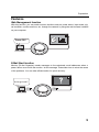
Web Management function
With this function, you can watch monitor functions such as power status, input mode, signal condition, monitor-use time, etc. through the network by using the web browser installed
on your computer.
Power ON !
E-Mail Alert function
Monitor (PJ-Net Organizer) sends messages to the registered e-mail addresses when a
power failure occurs with the monitor. In this message, it describes how to solve the cause
of the problems. You can take efficient action for quick recovery.
You've got mail !
5
Preparation
Recommended Operating Environment
To perform the management and setting up the monitor using this product, the environment described below is required.
Operating System
Windows 2000 sp4 or later
Windows XP sp2 or later
Web Browser*
Internet Explorer version 6.0 or 7.0
* Used to control and set up the monitor. The layout of pages in
the browser may slightly differ from each type of application or
operating system you use.
Plug-Ins
Adobe Flash Player version 9,0, 28,0 or later
Computer
Environment
Network
Environment
The computer must provide a 10Base-T or 100Base-TX network
card.
Internet Mailer*
- Microsoft Outlook
Network must handle Ethernet correctly and accept TCP/IP.
- Microsoft OutlookExpress
* Required the internet e-mail application software to receive an
e-mail alert sent from this product. If you do not use the function E-mail Alert, this application is not required.
The limitation of connection between this product and Hub or
Computer
Suitable LAN cables are limited by length and type as follows;
Connection
Type of usable LAN cable
Maximum length
PJ-Net Organizer - Hub
UTP Straight Cable with category 3 or 5
100m
PJ-Net Organizer - Computer UTP Cross Cable with category 3 or 5
100m
✐ Category of LAN cable indicates the cable quality. Normally, cable with category 3 or 5 is used for
10Base-T network and cable with category 5 is used for 100Base-TX network.
✐ There may be other limitations depending on your network environment or LAN specification.
Please contact your network administrator for further details.
6
1
Installation
7
Installation
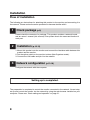
Flow of installation
The following are instructions for attaching this product to the monitor and connecting it to
the network. Please review the entire procedure to become familiar with it.
1 Check package (p.9)
Please check the contents of a package. This product contains a network board,
and an ownerʼs manual (this manual). Also please check the name and function of
each part.
2
Installation (p.10-12)
1. Mount this product onto the monitor and connect the interface cable between this
product and the monitor.
2. Set the option switch on the monitor to down (Net-Organizer mode).
3. Connect the LAN cable and join it to the network.
3 Network configuration (p.13-19)
Configure the network with the computer.
Setting up is completed.
The preparation is completed to control the monitor connected to the network. At next step,
set up and control the monitor via the network by using the web browser installed on your
computer. Please see “Basic setting and operation” on page 21.
8
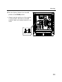
Name and function of each part
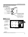
Name and function of each part
Network Board
Power indicator
This illuminates red when the
network board is mounted
onto the monitor and the AC
plug is connected .
Serial port
Connecting the Serial cable.
LAN port
LINK indicator (Orange)
Connecting the LAN cable.
This illuminates orange when
the network board is connected
to the network correctly.
ACT indicator (Green)
This turns on and off when
sending or receiving of data
Monitor
(Rear Terminal of Monitor)
Input port
Connecting the output connection from
the network board.
Option Switch
Set to the down
position for the network
board use.
✐ Set back to the
UP position
when the network
board is not used.
!
(LCD) Monitor
Caution
✐ Do not touch the connector. It may damage the product.
9
Installation
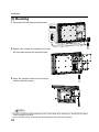
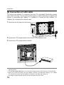
[1] Mounting
1 Disconnect the AC plug from the monitor.
2 Remove the screws on the back of the cabinet, and then remove the terminal covers.
3 Insert the network board into the monitor,
and fix it with the screws.
!
Caution
✐ The AC cord must be disconnected from AC power outlet when mounting or removing this product.
It may damage the product.
✐ Do not connect the AC cord until after connecting the LAN cable and computer.
10
Mounting
4 Set
the Option Switch from the UP
position to the DOWN position.
PC - IN
H
D
M
I
✐ Cannot use the serial port of the monitor
in this position. Set back to the UP
position when the network board is not
used.
L
R
L
R
AV2-IN
AV2-OUT
SERIAL
PORT-IN
SERIAL
PORT
NET
Organizer
SERVICE
R
PR
R
G
Y
G
Y
B
PB
B
PB
PR
SERIAL
PORT-OUT
AV3
VIDEO-IN
AV1
AV3
VIDEO-OUT
H/V
H/V
V
V
N4JF
Up
Down
Position Position
11
Installation
[2] Connection of LAN cable
To connect to the network, it is required to use the UTP (Unshielded Twisted Pair) straight
cable with RJ-45 plug. There are two different types of cables depending on whether the
network is constructed with 10Base-T or 100Base-TX. Prepare the Hub (10Base-T or
100Base-TX) to distribute the network cable.
1 Disconnect the AC plug from the monitor.
2 Connect the UTP straight cable to the LAN port on the network board.
3 Connect the UTP straight cable to the hub.
✐ The AC cord must be disconnected from AC power outlet when connecting the cable. It may damage the product.
✐ Use the UTP cross cable when you connect the computer and monitor directly not using the hub.
✐ When you connect the monitor into the 10Base-T network, use cable with category 3 or 5. When
you connect the monitor into the 100Base-TX network, use cable with category 5.
✐ The length of cable between hub and monitor should be less than 100m.
12
Network configuration
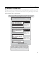
[3] Network configuration
When you connect a monitor to a network, the network number of monitor must be the
same as the network you intend to connect. You should configure monitorʼs network first.
Make sure that the monitor is connected to the network correctly. To configure the network,
use the computer. Refer to the chart below.
Procedure of Connecting the monitor to the network
Configure the network with computer
Temporarily set up the computer's
network with the default network
number of the PJ-Net Organizer.
Restart the Computer, if required
Using the web browser and login to
the setting page of the PJ-Net
Organizer by accessing the default
IP address.
Change the network address you
want to connect to the existing
network through the setting menu
on the browser.
p.14
Please see further
informatin on pages
14-19.
Example of monitor's configuration
IP Address : 192.168.0.5
Subnet Mask : 255.255.255.0
Default Gateway : (blank)
DNS : (blank)
Please see further
informatin on pages
22-25.
Default Network Address of the PJNetOrganizer
IP Address : 192.168.0.2
Subnet Mask : 255.255.255.0
Default Gateway : 0.0.0.0
DNS : 0.0.0.0
Example of monitor's configuration
IP Address : 172.21.95.224
Subnet Mask : 255.255.255.0
Default Gateway : 172.021.095.001
DNS : 172.21.1.53
Restart the PJ-Net Organizer
Reset to the computer's original
network configuration.
Completing the network configuration. Perform the basic
setting and operation of the monitor by using the web
browser. Please see chapter "2: Basic Setting and
Operation" on page 21 for further information.
13
Installation
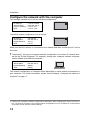
Configure the network with the computer
This example explains how to set the following configuration.
IP Address
Subnet Mask
Default Gateway
DNS
:
:
:
:
172.21.95.224
255.255.255.0
172.21.95.1
172.21.1.53
The default network configuration is set as follows.
IP Address
Subnet Mask
Default Gateway
DNS
: 192.168.0.2
: 255.255.255.0
: 0.0.0.0
: 0.0.0.0
Make sure that the monitor is connected to the network and then connect the AC cord to
the outlet.
1 Temporarily*
set up your computer network configuration to the same IP network number as the PJ-Net Organizer. For example, change your computer network configuration as follows and restart the computer.
1
IP Address
Subnet Mask
Default Gateway
DNS
: 192.168.0.5
: 255.255.255.0
: (blank)
: (blank)
The network configuration of computer differs depending on each network environment or
your computer. For further information, please see the chapter “Configure the network of
computer” on page 17.
*1 Change your computerʼs network configuration temporarily. After completing the set up for the monitor, you must set up again to the original network configuration for your computer. It is recommended to make a note of those network settings.
14
Network configuration
2 Configure the network of the monitor by using the web browser.
1. Enter the IP address of the monitor as the URL. The login page will be displayed and
login. For further information, please see chapter “2: Basic Setting and Operation” on
page 21.
2. Configure the network through the setting page on the browser. For further information, please see chapter “Network Configuration” on page 25.
Completing of installation
Now the installation is completed. The IP address of this monitor has been set to
“172.21.95.224”. You must reset the network configuration of the computer to the original and restart the computer.
Next, please see chapter “Basic Setting and Operation” on page 22 It describes how to
operate and set up the monitor .
✐ If you use a cable to connect the monitor and computer directly, without using a hub, you must use
a UTP cross cable. In this case, you cannot access the login page if the setting of web browser is
set to “Use proxy server”. It must be changed to the “Not use proxy server”. For further information,
please see the “Web browser setting” of chapter "Appendix" on page 46.
✐ When you set up the network of monitor which has a default setting by using the computer, it must
be carried out in the network which does not provide any gateways (routers).
15
Installation
Flash Player
The Flash Player version 9 or later is required when you control the monitor.
If your computer does not have, follow to the message on the control page
to install the Flash Player. For further product information or installing,
see the homepage. (http://www.adobe.com)
16
Installation
Configure the network of computer
Configure the network of computer
When you use the monitor through the network, the IP address of the monitor
must have the same IP network number of the existing network. Also it is required to
use the same IP network number of the computer to set up the monitor. In the network
included with the gateway (router), it must be used with the IP network number specified
by the gateway (router).
Configure the computer's network by following steps:
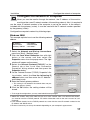
Windows 2000
This example explains how to set the following network
address.
IP Address
: 192.168.0.5
Subnet Mask
: 255.255.255.0
Gateway Address : 192.168.0.1
1 Select
2
3
4
5
the Network and Dial-up Connections
menu from [Start] - [Settings] menu.
Click the Local Area Connection icon with right
button of the mouse and then select the
Properties menu from the popup menu. The right
window will appear on the screen.
Select the Internet Protocol(TCP/IP) *1 on the
General tab of the "Local Area Connection
Properties" dialog window and then press the
Properties button.
On the "Internet Protocol (TCP/IP) Properties" dialog window, select the Use the following IP
address button and then enter the IP Address*2
and Subnet mask.
Enter the Default gateway address.
✐ This setting is not needed if the network does not provide the gateway (router).
6 Click
the OK button, the setting window will be
closed.
✐ To change the configuration, you may need administrator privileges.
*1 Select the "TCP/IP" item of the LAN card you use. If the "TCP/IP" item is not listed in the column,
you need to install the TCP/IP protocol. For further information refer to the user's manual of your
computer.
*2 If the network already has the TCP/IP protocol set, enter with the same IP network number for the
IP address and Subnet mask.
*3 There are some ways to set up the network depending on your computer's appearances.
17
Configure the network of computer
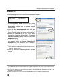
Windows XP
This example explains how to set the following network address.
IP Address
: 192.168.0.5
Subnet Mask
: 255.255.255.0
Gateway Address : 192.168.0.1
1 Select
2
3
4
5
the Control Panel menu from the [Start]
menu. Click the Network and Internet
Connection and then click the Network on the
control panel.
Click the Local Area Connection icon with right
button of the mouse and then select the Property
menu. The right window will appear on the screen.
Select the General tab on the "Local Area
Connection Properties" dialog window. Select the
Internet Protocol(TCP/IP)*1 and then press the
Properties button.
On the "Internet Protocol (TCP/IP) Properties" dialog window, select the Use the following IP
address button and then enter the IP address*2
and Subnet mask.
Enter the Default gateway address.
✐ This setting is not needed if the network does not provide the gateway (router).
6 Click
the OK button, the setting window will be
closed.
*1 Select the "TCP/IP" item of the LAN card you use. If the "TCP/IP" item is not listed in the column,
you need to install the TCP/IP protocol. For further information refer to the user's manual of your
computer.
*2 If the network already has the TCP/IP protocol set, enter with the same IP network number for the
IP address and Subnet mask.
*3 There are some ways to set up the network depending on your computer's appearances.
18
Installation
Notice about system construction
In case of installing the monitor with PJ-Net Organizer into the network
constructed with the DHCP/BOOTP server.
This PJ-Net Organizer does not support the DHCP/BOOTP server. The static IP address
must be configured by the manual. To use this product in this network environment, set it
up so that the DHCP/BOOTP server does not assign the IP address configured to this
product for another device on the network. Please contact your network administrator for
further information.
19
Note
20
2
Basic Setting and Operation
21
Basic Setting and Operation
This chapter describes basic operations and settings for controlling the monitor via a network using this product. It is required that computer and monitor are connected to the network and the network address be properly configured.
Login the setting page of the monitor
1 Enter the IP address
Launch the web browser installed in your
computer, enter the IP address into the
"Address" on the browser and the press the
“Enter” key.
Enter the IP address that you configured in chapter “Network Configuration” on page 13. The
default IP address is [192.168.0.2].
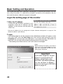
2 Login
If the setting page has set the password, the authentication window will appear. In this
case type "user" onto the User Name text area and the login password onto the
Password text area and then click OK button. If you check the item “Remember my
password”, you can login without entering the password for the next login.
* The entering User Name must be "user" and it cannot be changed.
[Note]
When accessing the monitor at first time or
setting the no password [0000], the autologin will be performed and the next main
setting page is displayed.
Important
If you have forgotton current
network configuration(IP
address, subnet mask, password DNS, and default gateway,
you can set them to default
value via serial port (RS232C)
Refer to page 42
22
Login the setting page of the monitor
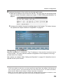
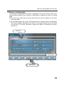
3 Display of setting page
The following setting page of the monitor is displayed. Perform the various kinds of setting through this page. Press a button of Main Menu to display the control or setting
page.
☛ The main menu which can be set up and control the monitor appears on the lower
side of the page.
☛ On the setting page, the control and status items for selected menu are displayed.
The "Status" page is displayed as the default. This page indicates the current status
of the monitor. For further information, please see chapter “Controlling the monitor”
on page 31.
Sub Menu
Setting Page
Main menu
23
Basic Setting and Operation
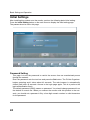
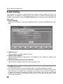
Initial Settings
After installing this product onto the monitor, perform the following basic initial setting.
Press the Initial Setting button on the main menu to display the initial setting page.
The password can be set in this page.
Password Setting
This page is to set the password to restrict the access from an unauthorized person
through the network.
Enter the password onto the text box and press the Set button. The PJ-Net Organizer
begins restarting and it takes about 40 seconds. The web browser is automatically
closed (Quit) after 40 seconds. Access to the login page again. This is to perform the
login authentication firmly.
The default password [0000] means no password. You should change password from
the default in normal use. When you connect the monitor with this product to the network, you should set a password. Only a four-digit numeric number is valid characters
for the password.
24
Network Configuration
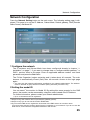
Network Configuration
Press the Network Setting button on the main menu. The following setting page is displayed. This page is to set the IP Address, Subnet Mask, Default gateway, DNS (Domain
Name Server) and Model ID.
1 Configure the network
The IP address and Subnet Mask have been configured already in chapter “1:
Installation” on page 7. If you want to change them or configure default gateway*1 or
DNS*2, perform them in this page. Enter an applicable address number onto each
parameter and press the Set button.
The PJ-Net Organizer begins restarting and it takes about 40 seconds. The web
browser is automatically closed (Quit) after 40 seconds. Access to the login page
again.
✐ You must use the network configuration specified by your network administrator. The address
must be entered as group with four numbers split by a dot like [192.168.1.101].
2 Setting the model ID
You can name*3 the monitor for Model ID. By setting this name properly for the DNS
server, the monitor can be accessed by using this name instead of the IP address.
For further information, please contact your network administrator.
✐ Up to 10 characters can be registered.
*1 Set [0.0.0.0] if the network does not provide the gateway (router).
*2 Set [0.0.0.0] if you do not use the function E-Mail alert.
*3 If you use the DNS server, register the host name to the DNS server as a monitor name.
You can access with this monitor name from any computers in your network. If you do not use the
DNS server, access with the assigned IP address to the monitor.
25
Basic Setting and Operation
E-mail Setting
This product has an E-mail function which can send an alert message to users or an
administrator if it detects an abnormality on the monitor or when the panel usage time
reaches to setting time. Press the E-Mail Setting button on the main menu and follow the
below steps.
1 E-mail Setting
Select "E-mail Setting" of sub menu, type below items, and press the Set button for setting.
1-1 SMTP Server*1
Type the address of SMTP server for E-mail.
1-2 Administrator Address
Type the E-mail address of administrator. This address is set to "Reply-To" address sent
from the monitor.
1-3 Registering and deleting E-mail addresses
Type the E-mail address to which an alert message is sent.
*1 The SMTP server is a server for sending E-Mail. Please contact your network administrator to have
this SMTP server address.
✐ To use the E-Mail function, it must be set the DNS address on the Network Setting page correctly.
✐ You cannot use this E-mail function if the DNS server and SMTP server cannot be used in your network environment. If the SMTP server is located in your LAN (Local Area network), the address set
to SMTP server should be specified the in SMTP server located in your LAN. The server located
outside of your LAN may not be available for security reason. For further information please contact
your network administrator.
26
E-mail Setting
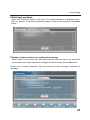
2 Mail Check and Delete
Select "Mail Check and Delete" of sub menu. The registered address is displayed as the
"Mail To" address. To delete the registered address, check the box and press the Delete
button.
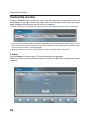
3 Option (Condition selection for sending alert message)
Select "Option" of sub menu.Type the panel usage time that you want to set, and check
the condition items under which alert messages will be sent and press the Set button.
Please refer to chapter “Examples :Type and contents of alert messages” described on
next page.
27
Basic Setting and Operation
Examples: Type and contents of alert mail
When the monitor has an abnormality, the following alert messages are sent to the registered E-mail address according to your selected condition. Administrator or user can take
an efficient action quickly by receiving this massage. This is very useful to maintain and
service the monitor.
The following are examples of received messages.
●When the set has failed:
TITLE: Message from Monitor
Monitor Model Name: 42LM4
TCP/IP: 192.168.0.2 Monitor Name: MYLCD-1
It sends you following message.
Error! The set has failed
●When the internal power circuit has failed:
TITLE: Message from Monitor
Monitor Model Name: 42LM4
TCP/IP: 192.168.0.2 Monitor Name: MYLCD-1
It sends you following message.
Error! Power circuit has failed
✐ The Monitor was turned off, because the monitor power circuit failed.
Unplug the monitor from AC outlet and ask servicing to a qualified service personnel.
●When panel usage time reaches 30,000 hours:
TITLE: Message from Monitor
Monitor Model Name: 42LM4
TCP/IP: 192.168.0.2 Monitor Name: MYLCD-1
It sends you following message.
Information! Panel usage time has reached "30,000" hours.
28
SNMP Setting
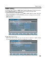
SNMP Setting
This product can be used for SNMP (Simple Network Management Protocol) function.
Press the SNMP Setting button on the main menu and follow the below steps.
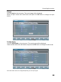
1 LCD Information (Setting SNMP Agent)
Select "Information" of sub menu, type the MIB of SNMP agent (A contact name and
a place of this product) or a community name (reference or setting) and press the Set
button for setting.
✐ MIB: Management Information Base
2 Trap Send (Setting Trap)
Select "Trap Send" of sub menu, type the host name (IP address) of SNMP manager
(PC) and a community name, and press the Set button for setting.
29
Basic Setting and Operation
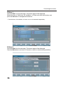
3 Trap Check and Delete
Select "Trap Check and Delete" of sub menu. The registered trap is displayed. To delete
it, check the box and press the Delete button.
4 Trap Option (Selection for sending alert message)
Select "Trap Option" of sub menu.Type the panel usage time that you want to set, and
check the condition items under which alert messages will be sent and press the Set
button.
30
3
Controlling the Monitor
31
Controlling the Monitor
Check the status of monitor
In the "Status" page, you can check the status of the monitor as follows:
1 Status 1
Power:
Input:
Condition of Power
Power ON / Power Error / Power OFF
Input Mode
AV1 / RGB / AV2 RGBHV / AV2 YPbPr / AV3 / HDMI / PC
Video Signal: Availability of Input Signal
Yes / No
Panel Usage: Accumulated Panel-use Time
Wide:
Picture:
Example: 163H (hours)
Wide Mode
Auto / Natural / Zoom 16:9 / Title in 16:9 / Zoom 14:9 / Title in 14:9 /
Full / Normal
Condition of Picture
Dynamic / Standard / Eco / Personal
✐ The Monitor was turned off in "Power Error", because the monitor power circuit failed.
Unplug the monitor from AC outlet and ask servicing to a qualified service personnel.
32
Check the status of monitor
2 Status 2
Child Lock:
Key Lock of Monitor
OFF (Unlock) / On
RC Inhibition: Button Lock of Remote Control
OFF (Unlock) / On
Power save: The monitor turns into power save mode,
after 1 minute with no signal.
Off/On
33
Controlling the Monitor
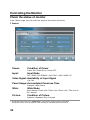
Control the monitor
Press the Control button on the main menu. The sub menu for controlling the monitor will
be displayed on the upper side of the page. When you click each control item, the control
page is displayed according to the sub menu you selected.
✐ Please see the owner's manual of the monitor to have the further information of each control item.
✐ The control page displays valid control items depending on the selected input mode, signal or functions of the monitor you use, therefore, there may be different controls between the described items
and actual control items on the page display.
✐ When the monitor is turned off, only the power control is effective; others are inactive.
1 Power
Click the Power on the sub menu. The control page will be displayed.
Select the power condition with radio button and press the Set button to change the power
condition.
34
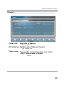
Controlling the monitor
2 Input
Click the Input on the sub menu. The control page will be displayed.
Select an input source with radio button and press the Set button to change the input
source.
3 Wide Mode
Click the Wide Mode on the sub menu. The control page will be displayed.
Select a wide mode with radio button and press the Set button to change the wide mode.
The wide mode cannot be changed depending on the input signal.
35
Controlling the monitor
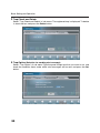
4 Other 1
Click the Other 1 on the sub menu. The control page will be displayed.
Select the item of Child Lock, RC Inhibition, or Power save with radio button and
press the Set button to change these functions.
✐ The Child Lock, RC Inhibition, or Power save can be selected independently.
5 Other 2
Click the Other 2 on the sub menu. The control page will be displayed.
Press the Set button to set Auto PC function or return to factory setting condition.
36
Controlling the Monitor
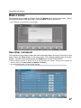
Make a memo
This function can be used as a memo. Press the Memo button on the main menu. The following setting page will be displayed. Press the Save button to memorize.
✐ The maximum 127 characters can be typed.
Use other command
This function can be used to send other command which does not have in the menu of this
board. Press the Other button on the main menu. The following setting page will be displayed. Type the command and press the Send button to control the monitor.
✐ Please see the chapter "4: Serial Port Use" on page 39 or the owner's manual of the monitor for
other command. ("Configurations of RS232C Terminal")
✐ The box of Explanation can be used for the title.
37
Note
38
4
Serial Port Use
39
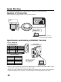
Serial Port Use
This Network Board provides with a serial control port (RS232C) to control the monitor.
Example of Connection
Control the monitor through network and serial control function.
AV1
Power ON !
RS232C serial cable with
reverse type (Not supplied)
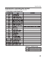
Specification and Setting of RS232C Terminal
Terminal : HDB9-PIN
Pin Configuration
1
2
3
4
5
No Connect
RxD
TxD
No Connect
Ground
6
7
8
9
No Connect
No Connect
No Connect
No Connect
9
8
7
6
5
Connection
4
3
2
1
Interface (Fixed)
Protocol
Baud rate
Data length
Parity
Stop bit
Flow control
RS-232C
19200 bps
8 bits
1 bit
-
RS232C serial cable
with reverse type
(Not supplied)
✐ Exclusive driver software for control of this Network board is required. This product does not provide any driver software. Please consult your local dealer.
✐ There are 2 types of RS-232C serial cable, Normal and Reverse type. Usually, when connecting
between this product and a computer, use Reverse type of serial cable (Serial Cross Cable).
40
Serial Port Use
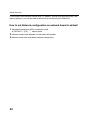
Command for controlling the monitor
The below commands for controlling the monitor can be used.
PSAVE
PSAVE
EXAMPLE : POWER ON (C00)
HEX
ASCII
FUNCTION CODE / END CODE
43h 30h 30h 0Dh 0Ah
'C' '0' '0' [CR] [LF]
41
Serial Port Use
If you forgot current network configuration, (IP address, subnet mask,password DNS, and
default gateway), you can set them to default value via the serial port (RS232C).
How to set Network configuration on network board to default
1 Send below command (ASCII) to network board
W_DEFAULT + [CR]
“_” means space.
2 Network board will be rebooted. It takes about 40 seconds.
3 Network board starts with default network configuration.
42
5
Appendix
43
Appendix
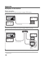
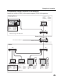
Examples of Connection
Direct connection
Connect the monitor (LCD01) to the control computer (PC05) directly.
Computer Name: PC05
IP Address
Subnet Mask
Default Gateway
DNS
: 192.168.0.5
: 255.255.255.0
:
:
Monitor Name: LCD01
IP Address
Subnet Mask
Default Gateway
DNS
: 192.168.0.2
: 255.255.255.0
: 0.0.0.0
: 0.0.0.0
* UTP cross cable
Connect the monitor (LCD01) to the control computer (PC05) via the hub.
Hub
Computer Name: PC05
IP Address
Subnet Mask
Default Gateway
DNS
: 192.168.0.5
: 255.255.255.0
:
:
Monitor Name: LCD01
IP Address
Subnet Mask
Default Gateway
DNS
: 192.168.0.2
: 255.255.255.0
: 0.0.0.0
: 0.0.0.0
UTP straight cable
Computer Name: PC10
IP Address
Subnet Mask
Default Gateway
DNS
: 192.168.0.10
: 255.255.255.0
:
:
✐ When the monitor is connected to the computer directly without hub, the UTP cross cable
should be used .
44
Examples of connection
The gateway (Router) installed in the network
Connect the monitor (LCD01) to the control computer (PC05) via the gateway.
Meeting Room
Computer Name
IP Address
Subnet Mask
Default Gateway
DNS
: PC205
: 192.168.200.5
: 255.255.255.0
: 192.168.200.1
: 192.201.1.5
Monitor Name: LCD01
IP Address
Subnet Mask
Default Gateway
DNS
: 192.168.200.15
: 255.255.255.0
: 192.168.200.1
: 192.201.1.5
Hub
Network Group: 192.168.200.0
Gateway (Router)
To another network
IP Address : 192.168.200.1
IP Address : 192.168.100.1
IP Address : 192.168.10.1
Office
Hub
Hub
Computer Name: PC05
IP Address
Subnet Mask
Default Gateway
DNS
: 192.168.10.5
: 255.255.255.0
: 192.168.10.1
: 192.201.1.5
Computer Name
IP Address
Subnet Mask
Default Gateway
DNS
: PC10
: 192.168.10.10
: 255.255.255.0
: 192.168.10.1
: 192.201.1.5
Computer Name
IP Address
Subnet Mask
Default Gateway
DNS
: PC51
: 192.168.10.51
: 255.255.255.0
: 192.168.10.1
: 192.201.1.5
Computer Name
IP Address
Subnet Mask
Default Gateway
DNS
: PC61
: 192.168.10.61
: 255.255.255.0
: 192.168.10.1
: 192.201.1.5
Network Group: 192.168.10.0
45
Appendix
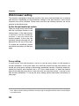
Web browser setting
This product is designed to enable the monitor to be set up and controlled from an Internet
web browser. Depending on the preference settings of the web browser, some control
functions may not be available. Please make sure that the following functions are set up
properly in the web browser.
Active Script/JavaScript enable
There are some control items used
with the JavaScript function in the
setting pages. If the web browser
is set not to use this JavaScript
function, it may not control the
monitor properly. In this case, the
following warning message will be
displayed on the top of the page.
To enable the JavaScript, please
see further instructions on the next
page.
Proxy setting
In some cases, your web browser is set up to use the proxy server for the internet or
intranet connection. In this case, when you install this product into the local network, you
should set up the proxy setting of web browser preference correctly. Especially when connecting the monitor and computer with a UTP cross cable directly, or when the network
does not provide the proxy server, make sure that “not use proxy server” is set up in your
web browser preference. To set up the proxy setting, please see further instructions on
next page.
✐ There are various ways to change your browser preferences depending on the version or applications. Please see the setting instructions on next page for example and also refer to on-line help of
your web browser.
46
Web browser setting
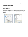
Examples: OS/Browsers
Windows XP Professional
Internet Explorer v.6.0
ActiveScript setting
Select the Internet Options menu from the Tool menu on the web browser and then select
Security tab and click Customize Level… button. On the security setting window, scroll
down and find the Scripting item, make sure that “Enable” is selected in item Active
Scripting.
47
Appendix
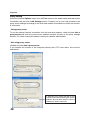
Proxy setting
Select the Internet Options menu from the Tool menu on the web browser and then select
Connection tab and click LAN Settings button. Properly set up your web browser's the
proxy server settings according to the local area network environment to which the monitor
is connected.
- Using proxy server
To use an external internet connection from the local area network, check the item Use a
proxy server and enter the proxy server address and port correctly in the proxy settings
window. For further instruction please consult your network administrator.
- Not using proxy server
Uncheck the item Use a proxy server.
If you connect the monitor to the computer directly with UTP cross cable, this must be
unchecked.
To designate proxy settings that will not use
the proxy server when accessing the monitor
installed in the local area network, enter the
IP address or domain name here.
48
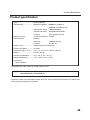
Product Specification
Product specification
Type ......................................Pj-Net Organizer
LAN interface ........................Applicant regulation IEEE802.3 (10Base-T)
IEEE802.3u (100Base-TX)
Data transfer speed
10Mbps/100Mbps
data transfer mode
Half duplex/Full Duplex
Terminal
8-pin modular (RJ-45)
Network protocol
TCP/IP specification
TCP/IP
Serial interface
RS232C
Baud rate
19.2Kbps (Fixed)
Terminal
D sub 9-pin
Power source ........................Supplied from the LCD monitor
Power consumption ..............3.0 watts
Dimensions (W x H x D)........4.2” x 1.4” x 5.3” (107 x 34.9 x 135mm)
Weight ..................................0.92 lbs (420 g)
Operating temperature ..........41˚F ~ 95 ˚F (5˚C ~ 35 ˚C)
Storage temperature ............14˚F ~ 140˚F (-10˚C ~ 60˚C)
Accessories
Owner's Manual
* The specifications are subject to change without notice.
Applicable monitor model
CE42LM4WPN-NA, CE42LM4N-NA
* The above model is the applicable monitor which can be connected for this product. For further information please consult your local dealer.
49
Appendix
Port Specification
LAN port specification
8-pin modular connector (RJ-45)
12 3 4 5 6 7 8
pin No.
Signal
1
2
3
4
5
6
7
8
TX+
TXRD+
(not used)
(not used)
RD(not used)
(not used)
Function
Transfer data (+)
Transfer data (-)
Receive data (+)
Receive data (-)
MAC Address
MAC Address
The MAC address is indicated on the rating label.
NOTES ON Lithium Battery (CALIFORNIA USA ONLY)
This product uses a Lithium Battery which contains Perchlorate Material - special han dling may apply. See www.dtsc.ca.gov/hazardouswaste/perchlorate
Notas acerca de pilas de litio(SOLO PARA CALIFORNIA, EE.UU.)
Este producto usa una pila de litio que contiene el material perclorato – puede ser nec esario una manipulación especial.
Consulte la página www.dtsc.ca.gov/hazardouswaste/perchlorate
50
Note
51
Printed in Japan
Part No. 610 333 5582 (1AA6P1P5387-- IFFNA)