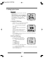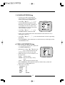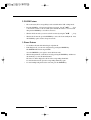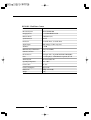
1
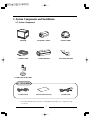
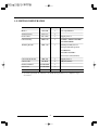
COLOR QUAD OBSERVATION
SYSTEM Installation Manual
SSC-21
CAUTION
RISK OF ELECTRIC SHOCK
DO NOT OPEN
CAUTION : TO REDUCE THE RISK OF ELECTRIC SHOCK, DO
NOT REMOVE COVER (OR BACK). NO USER
SERVICEABLE PARTS INSIDE. REFER SERVICING
TO QUALIFIED SERVICE PERSONNEL.
Graphic Symbol Explanation
The lightning flash with arrowhead symbol, within an
equilateral triangle, is intended to alert the user to the presence
of uninsulated ‘dangerous voltage’ within the product’s
enclosure that may be of sufficient magnitude to constitute a
risk of electric shock to persons.
The exclamation point within an equilateral triangle is intended
to alert the user to the presence of important operating and
maintenance (servicing) instructions in
the literature accompanying the appliance.
Warning - To Prevent Fire or Shock Hazard, Do Not Expose
This Monitor To Rain or Moisture.
1
IMPORTANT SAFEGUARDS
Caution
Power source is indicated on the rear of the set. It contains high-voltage parts. If you remove
the cover, it may cause fire or electric shock. Do not remove the cover by yourself. (Control
switches are at the front of the monitor).
1. Read Instructions : All the safety and operating instructions should be read before
the appliance is operated.
2. Retain Instructions : The safety and operating instructions should be retained for
future reference.
3. Heed Warnings : All warnings on the monitor and in the operating instructions
should be adhered to.
4. Follow Instructions : All operating and use instructions should be followed.
5. Cleaning : Unplug this monitor from the wall outlet before cleaning. Do not use
liquid cleaners or aerosol cleaners. Use a damp cloth for cleaning.
Exception. A monitor that is meant for uninterrupted service and that for some
specific reason, such as the possibility of the loss of an authorization code for a
CATV converter, is not intended to be unplugged by the user for cleaning or any
other purpose, may exclude the reference to unplugging the monitor in the cleaning
description otherwise required in Item 5.
6. Attachments : Do not use attachments not recommended by SAMSUNG as they
may cause hazards.
7. Water and Moisture : Do not use this monitor near water for example, near a
bathtub, wash bowl, kitchen sink, or laundry tub, in a wet basement, or near a
swimming pool and the like.
8. Accessories : Do not place this monitor on an unstable cart, stand, tripod, bracket,
or table. The monitor may fall, causing serious injury to a child or adult, and
serious damage to the appliance. Use only with a cart, stand, tripod, bracket, or
table recommended by SAMSUNG, or sold with the monitor. Any mounting of the
monitor should follow SAMSUNG’s instructions, and should use a mounting
accessory recommended by SAMSUNG.
2
9. Ventilation : Slots and openings in the cabinet are provided for ventilation and to
ensure reliable operation of the monitor and to protect it from overheating, and
these openings should never be blocked by placing the monitor on a bed, sofa, rug,
or other similar surface. This monitor should never be placed near or over a
radiator or heat register.
This monitor should not be placed in a built-in installation such as a bookcase or
rack unless proper ventilation is provided or SAMSUNG’s instructions have been
adhered to.
10. Power Sources : This monitor should be operated only from the type of power
source indicated on the making label. If you are not sure of the type of power
supply to your installation site, consult your SAMSUNG dealer or local power
company.
11. Grounding or Polarization : For monitors equipped with a 3-wire grounding-type
plug having a third(grounding)pin. This plug will only fit into a grounding type
power outlet. This is a safety feature. If you are unable to insert the plug into the
outlet, contact your electrician to replace your obsolete outlet. Do not defeat the
safety purpose of the grounding-type plug.
12. Power : Cord Protection-Power supply cords should be routed so that they are not
likely to be walked on or pinched by items placed upon or against them, paying
particular attention to cords at plugs, convenience receptacles, and the point where
they exit from the monitor.
13. Lightning : For added protection for this monitor during a lightning storm, or
when it is left unattened and unused for long periods of time, unplug it from the
wall outlet and disconnect the cable system. This will prevent damage to the
monitor due to lightning and power-line surges.
14. Overloading : Do not overload wall outlets and extension cords as this can result
in a risk of fire of electric shock.
15. Object and Liquid Entry : Never push objects of any kind into this monitor
through openings as they may touch dangerous voltage points or short-out parts
that could result in a fire or electric shock.
Never spill liquid of any kind on the monitor.
3
16. Servicing : Do not attempt to service this monitor yourself as opening or removing
covers may expose you to dangerous voltage or other hazards. Refer all servicing
to qualified service personnel.
17. Damage Requiring Service : Unplug this monitor from the wall outlet and refer
servicing to qualified service personnel under the following conditions.
a.
b.
c.
d.
When the power-supply cord or plug is damaged.
If liquid has been spilled, or objects have fallen into the monitor.
If the monitor has been exposed to rain or water.
If the monitor does not operate normally by following the operating instructions.
Adjust only those controls that are covered by the operating instructions as an
improper adjustment of other controls may result in damage and will often require
extensive work by a qualified technician to restore the monitor to its normal
operation.
e. If the monitor has been dropped or the cabinet has been damaged.
f. When the monitor exhibits a distinct change in performance-this indicates a need
for service.
18. Replacement Parts : When replacement parts are required, be sure the service
technician has used replacement parts specified by SAMSUNG or have the same
characteristics as the original parts.
Unauthorized substitutions may result in fire, electric shock or other hazards.
19. Safety Check : Upon completion of any service or repairs to this monitor, ask the
service technician to preform safety checks to determine that the monitor is in
proper operating condition.
4
FCC & ICES Information
Warning
This equipment has been tested and found to comply the limits for a class B digital
device, pursuant to part 15 of the FCC Rules and ICES-003 of Industry Canada.
These limits are designed to provide reasonable protection against harmful
interference when the equipment is operated in a commercial environment. This
equipment generate, uses, and can radiate radio frequency energy and, if not
installed and used in accordance with the instruction manual, may cause harmful
interference to radio communications. Operation of this equipment in a residential
area is likely to cause harmful interference in which case the user will be required
to correct the interference at his own expense.
User-Installer Caution
Your authority to operate this FCC verified equipment could be voided if you make
changes or modifications not expressly approved by the party responsible for
compliance to part 15 of the FCC Rules.
5
Contents
IMPORTANT SAFEGUARDS
2
1. System Components and Installation
7
1-1. SYSTEM Components
7
1-2. SYSTEM CONFIGURATION
8
1-3. Individual Component Installation
9
1-4. Basic System Installation
19
2. Connecting Peripheral Devices
20
2-1. To connect a PIR Sensor
20
2-2. To connect a VCR
20
3. System Overview
21
4. Part Names and Functions
22
4-1. Camera
22
4-2. Monitor
24
5. Setting Up the System
29
6. Specifications
34
6
1. System Components and Installation
1-1. System Components
MONITOR
STANDARD CAMERA
DOME CAMERA
CAMERA CABLE
CAMERA HOUSING
MOUNTING BRACKET
INSTALLATION MANUAL
POWER CORD
CAMERA MOUNT BRACKET
ACCESSORIES
ALARM CABLE
✳ If you have purchased only a monitor, you should directly purchase every component except
accessories.
7
1-2. SYSTEM CONFIGURATION
Model Name Quantity
Note
Monitor
SSC-21M
1
Color Quad Monitor
Standard Camera
SSC-21C
3
Dome Camera
SSC-21DC
1
Tapping Screw 2
Camera Housing
MHG-110
1
SCREW 1, SPRING WASHER 1,
PLANE WASHER 1
Mounting Bracket
SBR-120
1
Housing Assembly Screw 2
(hexagon socket head, cap screws)
L-WRENCH 1
PLASTIC ANCHOR 4
Screw 4 (for wall attachment)
Camera Mount Bracket
SBR-110
3
Tapping Screw 3
Camera Cable
MCB-60
4
60ft(1ft:0.3048m)
Installation Manual
ACCESSORY
1
Power Cord
ACCESSORY
1
Alarm cable
ACCESSORY
1
Alarm cable(1.5m)
✳ If you have purchased only a monitor, you should directly purchase every component except
accessories.
8
1-3. Individual Component Installation
1) INSTALLING STANDARD CAMERA (SSC-21C)
SSC-21C' s camera can be attached to the wall, ceiling or shelf using the camera mount bracket
(SBR-110).
• Choose an installation site that can sufficiently support the weight of the equipments to be
installed.
• Attach the camera mount bracket to the wall or ceiling using the supplied three screws
(M3 X L16).
• Adjust the camera to target the video location and tighten the bracket handle on the camera
mount bracket.
3 ✕ 12 sized
screws
wall or ceiling
9
2) INSTALLING DOME CAMERA (SSC-21DC)
• Remove the dome cover from the main body of the camera by turning the cover in a
counter clockwise direction with one hand while holding the body with the other.
• Connect the camera cable to the camera cable jack on the dome camera, then connect, and
the other end of the cable to the monitor's channel input jack.
10
• Attach the camera to the wall or ceiling using the supplied tap screws.
• Adjust the video location by swiveling the camera (PCB board) up and down, and adjust the
focus by turning the lens clockwise and counter clockwise.
• Put the dome cover back on the camera by rotating the cover clockwise.
✳ Caution: When removing or closing the dome cover, do not get dirt or dust on the cover.
11
3) CAMERA MOUNT BRACKET(SBR-110) & STANDARD CAMERA(SSC-21C)
! Overview
CAMERA MOUNT BRACKET (SBR-110) is used to attach the camera to a wall, ceiling or
shelf.
@ Installation
Explains the installation of CAMERA MOUNT BRACKET as wall as the installation of the
camera onto the CAMERA MOUNT BRACKET.
• Choose an installation site that can sufficiently support the weight of the equipments to be
installed.
• Attach the camera mount bracket to the wall using the supplied screws (M3 X L16).
• Adjust the camera to target the video location and tighten the bracket handle on the camera
mount bracket.
Install the camera on to the male screw of the Camera Mount Bracket by rotating the camera
in clockwise.
12
• Loosen the handle by turning it in a counter clockwise direction and then adjust the camera
position. Tighten the handle, turning it clockwise, and lock the camera in position.
• Connect the camera cable to the camera.
Handle
# Specifications
Use
: Indoor
Installation : Wall or Ceiling
Dimensions : 52 ✕ 53 ✕ 97(W ✕ H ✕ D)
Weight
: 150g
Operating Temperature : -10 °C ~ 50 °C
$ Accessories
SCREW (M3 ✕ L16) ---------- 3
13
4) MOUNTING BRACKET(SBR-120)
! Overview
MOUNTING BRACKET (SBR-120) is used to install camera housing to a wall.
@ Installation
•
Choose an installation site that can sufficiently support the weight of the equipments to be
installed.
•
Mark the mounting holes using the house mount bracket as a template, then drill pilot
holes (8 mm diameter, 45 mm depth), and then install and secure the plastic anchors.
At this time, cut away all exposed protrusions.
• Align the housing mount bracket over the plastic anchor holes, then firmly fasten the
tapping screws.
• Install the housing according to the following CAMERA HOUSING installation method.
# Specification
Use
: Indoor
Installation : Wall
Dimensions : 75 ✕ 115 ✕ 240(W ✕ H ✕ D)
Weight
: 500g
Operating Temperature : -10 °C ~ 50 °C
$ Accessories
Hexagon Socket Head Cap Screws ---------- 2
L- WRENCH ------------------------------------1
SCREW ------------------------------------------ 4
Plastic Anchor ----------------------------------- 4
Tapping Screw(M5 ✕ J5) ---------------------- 4
14
5) CAMERA HOUSING(MHG-110)
! Overview
CAMERA HOUSING (MHG-110) is the equipment that protects the indoor camera from the
operating environment so that the camera may perform safely.
@ Installation
This section explains how to install the camera within the HOUSING and how to install the
CAMERA HOUSING (MHG-110) onto the MOUNTING BRACKET (SBR-120).
• Loosen the two screws located in the REAR CAP of CAMERA HOUSING, then detach
the COVER BODY by pushing it in the direction of arrow.
Cover Body
Rear Cap
15
• Loosen two screws from the CAMERA HOUSING PLATE and detach from HOUSING.
• Slide the spring washer and plain washer onto the supplied screw (1/4-20UNF), then
install the camera onto the camera housing plate.
Camera Housing Plate
• Insert one end of the cable to CABLE GROUND (PG-13.5), then pull that end of the cable
from the inside of HOUSING.
16
•
Connect the cable to the camera, then set up CAMERA MOUNTING PLATE and the
camera in the appropriate place inside the HOUSING.
Camera Mounting Plate
•
Slide the camera body into the housing body in the direction of arrow, then install the two
supplied screws to the rear cap.
17
• Use the supplied two screws and L-WRENCH to set up the CAMERA HOUSING onto
WALL MOUNT BRACKET.
• Use the supplied L-WRENCH to slightly loosen the hexagonal groove SCREW located at
the bottom of WALL MOUNT BRACKET by turning it counter clockwise, then position
the CAMERA HOUSING by tilting and swiveling, and tighten the hexagonal groove
SCREW by turning it clockwise.
# Specifications
Use
: Indoor
Dimensions : 147 ✕ 100 ✕ 254(W ✕ H ✕ Dmm)
Weight
: 1kg
Operating Temperature : -10 °C ~ 45 °C
$ Accessories
SCREW(1/4-20UNF) --------- 1
SPRING WASHER ------------1
PLANE WASHER ------------ 1
18
1-4. Basic System Installation
Perform the following steps to install your system.
• Take the monitor out of the packaging box.
• Place the monitor where you would like to install it. Do not turn on power until installation is
complete
• Choose the place where you want to install the camera.
• Once the monitor and camera locations have been chosen, install the camera.
• Connect the cable to the jack on the back of the camera.
• Connect the other end to CAMERA IN on the back of the monitor.
(At this time, select the numbers and sequence of cameras.)
• Connect the camera you wish to install (as shown below).
• Connect the power cord between the monitor and the power outlet.
• When the Power switch on the front panel of the monitor is pressed, the equipment becomes
operational.
(Initially quad screen will be displayed.)
✳ After the power has been turned on, the CRT needs approximately 20 seconds of stabilization
period.
✳ The output signal of each camera can be used as an external input for another device.
✳ Connect an alarm cable between the Alarm jack and a VCR.
(Alarm line: gray, Reset line: brown, GND: black)
19
2. Connecting Peripheral Devices
2-1. To Connect a PIR Sensor
Camera alarm in jack
Sensor
in put
Sensor
Mount on
the camera
- An additional PIR sensor or external sensor can also be connected.
- The additional PIR sensor can be connected as shown in the above graphic.
- Sensor's trigger signal is NO (Normal Open).
- Sensor is not supplied. (Sold separately)
2-2. Connecting to a VCR
- Connect the VCR as shown above.
- Connect Time lapse VCR's Alarm in jack to Monitor Alarm out jack.(Color : Gray)
- Connect Time lapse VCR's Alarm reset jack to Monitor's Alarm reset jack.(Color : Brown)
- Connect Time lapse VCR's Ground to Monitor's Alarm Ground jack.(Color : Black)
20
3. System Overview
The purpose of Samsung Observation system is to provide economical yet on effective
surveillance method using more than one video camera.
System features are as follows:
•
•
•
•
•
•
•
•
•
•
•
•
•
High-quality video reproduction using Super HAD IT CCD
Real-time Quad system
Quad mode or four camera locations in full screen display
Still picture for each channel
Automatic sequential rotation of channels
Selectable dwell time
Alarm output connectivity to alarm system or fire detection system
Alarm Buzzer On/Off and Sound Select features
Auto detection of camera connections and video loss detection
Selectable ZOOM in location (X2 Zoom in on a location)
PIP (Picture-In-Picture) feature
Channel OSD (On Screen Display) title and time B'd line editing
Power save feature
(The CRT may be turned off to prolong its life and reduce power consumption.
Nothing will be displayed on the screen, but the recording and alarm features will operate
normally in the background.)
21
4. Part Names and Functions
4-1. Camera
Standard Camera
a
d
b
e
c
PIN NUMBER
SPEC
1
ALARM_OUT
2
VIDEO_OUT
3
GND
4
GND
5
AUDIO_OUT
6
12V DC
a
Lens
It has a focal length of 3.8mm and makes it possible for you to observe a relatively wide
area.
b
Microphone
Capable of picking up all sound in the vicinity of the camera location and transmitting to
the monitor.
c
Camera fitting groove
Enables the camera to be fixed onto the bracket.
You may install it either above or below the camera if necessary.
d
6-pin modular jack
Used to connect the camera to the monitor.
e
SENSOR jack
Used to connect the sensor to the camera.
22
Fixed Dome Camera
a
d
b
e
c
a
b
c
Fixed Focus Lens
Fixed-focus that has a lens attached to the camera.
Keep the camera free of dust or dirt.
PCB Board
It is an important part of the camera that carries out the main function.
Handle with care.
Camera Frame
Frame that provides support to the camera.
d
Dome Cover
Clear plastic cover that protects the camera. Take care not to scratch the cover.
e
6Pin modular jack
Used to connect the monitor.
PIN NUMBER
SPEC
1
N.C
2
VIDEO_OUT
3
GND
4
N.C
5
N.C
6
12V DC
✳ Fixed Dome Camera does not support alarm in feature nor audio feature.
23
4-2. Monitor
Monitor Controls - Front Panel
① Monitor ON/OFF and Alarm Reset
MONITOR ON/OFF
In the monitor screen OFF mode, the monitor switches to the power save mode outputting
only the VCR OUT signal.
✳ When an alarm occurs, while in the power save mode, Monitor screen turns on
automatically.
At this time, if the Monitor ON/OFF key is pressed, the Alarm will be cancelled.
However,the Monitor screen will not be turned off.
ALARM RESET
This key enables the cancellation of all Alarms, after one or more alarms have been
detected.
(Clears the alarm and turns off the buzzer)
② VOLUME
Enables the control of audio output volume.
It is possible to control the volume output while in Quad, Single, Auto Switcher, PIP, and VCR
Modes. (Except in the case of Alarm and Zoom modes)
Enter the volume mode by pressing the VOLUME key, then use the` ▲ a
` ▼ akeys to
control the output volume.
To exit the volume mode, press the VOLUME key again.
✳ While in the volume mode, if no keys are pressed for 5 seconds, the volume mode will
be cancelled.
24
③ MENU
Displays the SYSTEM MENU on the screen.
The setup is possible in all modes, except when an alarm occurs.
④ LED
Indicates the current status of Display Modes, both ZOOM and FREEZE.
Freeze : LED flashes in red during the freeze mode.
Zoom : LED flashes green in the zoom mode.
✳ When the display is in both Freeze and Zoom modes, LED will be lit in Orange.
⑤ VCR/ENTER
VCR
Displays the VCR reproduction input signal.
(Loss information for all channels will not be displayed.)
If VCR playback input signal is lost, the display shown will have a blue back screen.
ENTER
In QUAD, SINGLE, AUTO SWITCHER, and PIP MODE, this is used to store changes
made to preset values as well as to select or cancel the function.
⑥ CHANNEL SELECT
When switching to SINGLE MODE
Used when switching to SINGLE MODE from QUAD, AUTO SWITCHER MODE.
Main screen switch
Used when switching from Sub screen to Main screen in the PIP Mode.
Selected channel becomes the Main screen of PIP mode.
FREEZE Select/Cancel
Used to select or cancel Freeze mode for all or certain displayed channel(s) during Quad
mode.
The Freeze mode will be cancelled when the corresponding channel key is pressed while
in the Freeze mode.
ZOOM Area and CURSOR Movement
Used to move the Zoom Area and the Cursor while in System Mode.
Changing Preset values
In the System Setup Mode, use the` ▲ ▼ ˇ ˆ akeys to change the preset values.
25
⑦ ZOOM
Used to switch to the Zoom mode from Single and VCR Modes.
✳ Zoom Feature supports X2 Zoom in capability.
⑧ FREEZE
Enables selection or cancellation of Freeze feature in Single Display, VCR, and Zoom
Display Modes.
In the Freeze mode, it is used to cancel the Freeze feature.
⑨ MODE
Enables the Display Mode to switch sequentially in the order of QUAD ➡ AUTO ➡ PIP
respectively.
Corresponding LED lights are lit sequentially in the order of QUAD ➡ AUTO ➡ PIP each
time the MODE key is pressed.
QUAD : Displays four camera locations.
AUTO : Rotates sequentially according to duration of Auto Switcher time set in the
Menu Setup.
PIP
: Displays PIP (Picture-In-Picture) screen.
⑩ MAIN POWER
On/Off Switch for the main power.
26
Monitor Controls- Back Panel
① AC IN
Power input jack.
② CAMERA IN
A 6 Pin Modular jack used for video input and camera power input.
Pin Configuration of the 6 Pin Connector is as follows.
PIN NUMBER
27
SPEC
1
ALARM_IN
2
VIDEO_IN
3
GND
4
GND
5
AUDIO_IN
6
12V DC
③ CAMERA OUT
CAMERA OUT: This jack means a video output signal of each camera. You can use it when
connecting to an external device.
④ VCR IN/OUT
VIDEO IN : VCR video input jack.
VIDEO OUT : Video recording output jack.
⑤ AUDIO IN/OUT
AUDIO IN
AUDIO OUT
: VCR audio input jack.
: Audio recording output jack.
➅ ALARM
ALARM OUT
When an Alarm occurs, Alarm signal will output for the duration of Alarm Hold time.
ALARM RESET
If Alarm Reset Key is turned On, Alarm Reset signal has on output.
At this time, Alarm mode is cancelled.
When connecting an alarm cable, connect the S-VHS jack to the monitor, and then connect to the
VCR using the three-line cables.
(ALARM : GRAY LEAD,RESET : BROWN LEAD,GND : BLACK LEAD)
➆ MONITOR OUT
Monitor Out: This jack means an external output of the video signal that is output to the monitor.
You can use it when connecting to an external device.
28
5. Setting Up the System
Menu Setup
• Use this to set data for System operation, such as Time,
Date, Alarm, etc.
Whenever the MENU key is pressed, the Main Menu
will be displayed (except when in the ALARM Mode).
Move the cursor to the item to be set,` ▲ a
` ▼ athen
press the ENTER key to display the Sub Menu.
In the Menu mode, press the MENU key to exit the
System setup.
1. CHANNEL TITLE Setup
• This Menu allows you to change the title of each channel.
• Move the → to the desired channel then, using the
`ˇ a
`ˆ a
keys, move the cursor to the desired
input location.
• Use the` ▲ a
` ▼a
keys to locate the character to
be inputted.
(Characters available for input are shown at the
bottom of the screen as "Character table".)
Maximum of 8 characters can be entered for each
channel.
• Press the ENTER key after the input, This data is stored in the memory and the display
returns to the Main Menu screen.
2. DATE and TIME Setup
• Use this to set date, time and their format.
• Go to DATE TYPE,` ▲ a
` ▼ athen use the
`ˇ a
`ˆ a
keys to select the desired format.
'DATE TYPE'
<1> : YY/MM/DD, Type
<2> : MM/DD/YY, Type
<3> : DD/MM/YY, Type
• Select the item to change,` ▲ a
` ▼ athen use the
`ˇ a
`ˆ a
keys to input DATE and TIME.
• Press the ENTER key after the input, this data is now stored in the memory and the display
returns to the Main Menu screen.
29
3.Display Mode Setup
• Use this to display date, time, and Channel Title
display as well as to set the quadrant border color.
• Go to "TYPE",` ▲ a
` ▼ athen use the
`ˇ `
a ˆ akeys to select the display type
(ALL, TITLE, DATA & TIME, NONE).
• Go to "BORDER",` ▲ a
` ▼ athen use the
`ˇ a
` ˆ akeys to select the BORDER color
(BLACK, WHITE).
• Go to "LOSS INFO",` ▲ a
` ▼ athen use the
`ˇ a
` ˆ akeys to select either ON or OFF.
• Press the ENTER key, Where all the adjustments are stored in the memory and the display
will returns to the Main Menu screen.
✳ If LOSS INFO is set to OFF, video loss will not be detected in the event of actual Loss.
4.AUTO SWITCHER Setup
• Use this to set Channel Switching time while in the Auto Switcher and PIP modes.
• Select the desired channel,` ▲ a
` ▼ athen
use the` ˇ a
` ˆ akeys to set the Switching
time.
• Switching time can be between 0 to 30
seconds.
• When the switching time is set to "0" the
corresponding channel will be skipped during
channel switching
• Press the ENTER key, the setting procedure is
now completed and the display returns to the
Main Menu screen.
30
5. ALARM & BUZZER Setup
• Use this to select audio output channel for
alarm and video loss occurrence while in the
System operation Setup and Quad modes.
• Use the` ▲ a
` ▼ akeys` ˇ a
` ˆ ato set
the Alarm Hold Time Setting Mode. Alarm
Hold Time can be between 0 to 30 minutes; 59
seconds.When more than one Alarm occurs,
Alarm hold time goes comes into effect in the
order of the Alarm occurrence.
• Use the` ▲ a
` ▼ akeys` ˇ a
` ˆ ato set
ALARM and LOSS to either ON or OFF.
• If ON is selected, Channel Audio will be muted and buzzer will sound in the event of
alarm trigger or video loss.
• Use the` ▲ a
` ▼ akeys` ˇ a
` ˆ ato select the desired channel for Audio output during
Quad Mode.
• Press the ENTER key, all the adjustments are stored in the memory and the display returns
to the Main Menu screen.
6. VIDEO ADJUSTMENT Setup
• Use to set up items concerning video signals such
as CONTRAST, BRIGHT, etc.
• Select the item to change,` ▲ a
` ▼ athen use the
`ˇ a
` ˆ akeys to change the numerical value.
A numerical value can range from 0 to 100.
• "EXIT" will allow you to choose whether to save
the changed data.
"SAVE" : Saves the changes
"PRESET" : Resets all the setting to factory
preset.
"QUIT" : Exits the setup mode without saving.
• Press the ENTER key, all the adjustments will be stored in the memory and the will
display returns to the Main Menu screen.
✳ Preset values of all setting
CONTRAST : 80
BRIGHT
: 50
COLOR
: 50
TINT
: 50
SHARP
: 50
EXIT
: PRESET
31
ALARM/ZOOM/FREEZE Operation
1. ALARM Feature
• When an alarm occurs, all functions of the monitor are temporarily paused and the monitor
switches to the Alarm Display mode.
• When an alarm trigger is received, the corresponding channel will be displayed in Single
Display mode with the letter "A" shown at the bottom left of the full screen.
• When more than one alarm occurs, the monitor will automatically switch to Quad Display
mode and the letter "A" will be displayed at the bottom left quadrant of the corresponding
channels.
• While in the Alarm mode, you can still change the screen by using the MODE and CH
keys. However,you will not be able to set up Zoom, Freeze, and Menu.
• While in the Alarm mode, if the ALARM RESET key is pressed or the Alarm Hold Time
has elapsed, all Alarms will be cancelled and the monitor will switch back to the previous
mode.
• If an alarm cable is connected between a monitor and a VCR, both Alarm and Reset
signals output from the monitor will become input signals for the VCR.
Terminal Name
Signal Level
Alarm Reset
VIH: 4~5V
VIL : 0~0.6V
T: 400 ms LOW output
Output
Alarm Out
VIH: 4~5V
VIL : 0~0.6V
T: LOW output during Alarm Hold Time
Output
< Monitor rear panel >
32
Signal Type
2. ZOOM Feature
• The zoom feature (X2 zoom capability) can be used while in the VCR or Single mode.
• Press the ZOOM key. A Zoom Area will appear on screen. Use the` ▲ ▼ ˇ ˆ akeys
to move the Zoom Area to the area which you would like the monitor to zoon in on and
then press the ENTER key to view X2 zoom screen.
• While in X2 Zoom mode, you can move the Zoom Area by using the` ▲ ▼ ˇ ˆ akeys.
• While in the Zoom mode, press the ENTER key to exit to the Zoom standby mode. Press
the ZOOM key again to return to the previous mode.
3. Freeze Feature
• Use the Freeze Feature while in the Single or Quad mode.
• In the Single mode, you can view a still picture by pressing the FREEZE key.
The FREEZE LED on the front panel blink.
Press the FREEZE key once again to cancel the Freeze mode.
• When in the Quad mode, set the Freeze mode by pressing the FREEZE key and then use
the channel keys to select the desired channel.
The letter "F" will be displayed to the left of the corresponding channel title.
To cancel the Freeze mode, press the corresponding channel key again.
• To cancel multiple still pictures at the same time, press the FREEZE key.
33
6.Technical Specifications
SSC-21M : Monitor
Specifications
Model Name
SSC-21M
Broadcast System
Standard NTSC
Picture Tube
21 Inch CRT, 0.71mm stripe pitch, 90°
deflection Visible screen size: 50.8 cm
(20 inch) (measured diagonally)
Horizontal Resolution
450 lines
Video Input/Outputs
4 Channel Input/Output
VCR In /Out, Monitor Output
Input Signal
Video Signal: Composite 1Vp-p
Video Signal: 0.714Vp-p,Sync
Signal:0.286Vp-p
3.579545MHz ± 500Hz
Color subcarrier frequency sync range
(at room temperature)
Range of horizontal sync frequency (HSF)
15.75KHz ± 500Hz
Range of vertical sync frequency (VSF)
60Hz ± 5Hz
High Voltage
25KV ± 1.5KV
Power Consumption
90Watts (Maximum) with 4 camera
Convergence
1.0 mm ≤ (at center of picture)
Power Source
AC110V~220V(60Hz)
Operating Humidity Range
0~90%
Operating Temperature Range
0~40°C
Audio Output
1.0 Watts
Dimensions
W:490mm, H:444mm, D:482mm
Weight
without packing
26 kg
34
SSC-21C : Standard Camera
Model Name
SSC-21C
Broadcast System
NTSC STANDARD
Imaging Device
1/3" SUPER HAD IT CCD
Effective Pixels
510(H) ✕ 492(V)
Synchronization
Internal
Resolution
H :330 TV Lines, V: 350 TV Lines
Signal Output
VBS 1.0Vp-p (75ohm composite)
S/N Ratio
≤ 50 dB
Minimum Object Illumination
2lux (F2.0, 50 IRE)
Gamma Correction
0.45
I/O Connectors
A/C input, Video outputs: MODULAR CABLE(60ft)
Lens
Focal Length (f) : 3.8mm, Relative Aperture (F) : 2.0
Shutter System
Electronic Shutter lris
Audio
-40dB Condenser Microphone Inclusion
Operating Temperature
-10 ~ + 50°C
Power Source
DC 12V
Power Consumption
Approx. 2W
Dimensions
Weight
51.8mm(W) ✕ 50.3mm(H)✕ 96.5mm(L)
150g
35
SSC-21DC : Fixed Dome Camera
Model Name
SSC-21DC
Broadcast System
NTSC STANDARD
Imaging Device
1/3" SUPER HAD IT CCD
Effective Pixels
510(H) ✕ 492(V)
Synchronization
Internal
Resolution
H :330 TV Lines, V: 350 TV Lines
Signal Output
VBS 1.0Vp-p (75ohm composite)
S/N Ratio
≤ 50 dB
Minimum Object Illumination
2lux (F2.0, 50 IRE)
Gamma Correction
0.45
I/O Connectors
A/C input, Video outputs:MODULAR CABLE(60ft)
Lens
Focal Length (f) : 3.8mm, Relative Aperture (F): 2.0
Shutter System
Electronic Shutter lris
Operating Temperature
-10 ~ +50°C
Power Source
DC 12V
Power Consumption
Approx 2W
Dimensions
Weight
100(φ) ✕ 67mm(H)
150g
36
Memo
37
Memo
38
Samsung CCTV dba GV1
1621 West Crosby, Suite 104
Carrollton, TX. 75006
PHONE : 866.492.8246
Part No.: AA68-02504A
Printed in Korea