1
Setting the Standard With the
World's Most Valued Grinders.
384
MANUAL
BEDKNIFE GRINDER
This book consists of two manuals:
The OPERATORS MANUAL which contains all the
information on operating and doing routine daily
maintenance on this equipment.
The ASSEMBLY and SERVICE MANUAL which is
used by the maintainence department to install the
equipment and to do all maintenance except routine
daily maintenance.
1
Setting the Standard With the World's Most Valued Grinders.
W e are committed to:
Providing superior customer support, training,
and service.
Manufacturing the highest quality products at an
unequaled value.
Setting the industry standard by investing in
technological product innovation.
Manufacturing products specifically designed to
maintain original equipment manufacturers'
specifications.
Interacting with and supporting all original
equipment manufacturers.
2
384
MANUAL
BEDKNIFE GRINDER
OPERATORS
MANUAL
WARNING
You must thoroughly read and understand this manual
before operating the equipment, paying particular
attention to the Warning & Safety instructions.
3
3847953 (7-03)
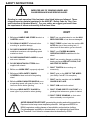
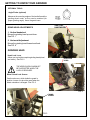
SAFETY INSTRUCTIONS
Safety Awareness Symbols are inserted into this
manual to alert you to possible Safety Hazards. Whenever you see these symbols, follow their instructions.
The Warning Symbol identifies special instructions
or procedures which, if not correctly followed, could
result in personal injury.
The Caution Symbol identifies special instructions
or procedures which, if not strictly observed, could
result in damage to or destruction of equipment.
1. KEEP GUARDS IN PLACE and in working
order.
13. MAINTAIN GRINDER WITH CARE. Follow
instructions in Assembly and Service Manual for
lubrication and preventive maintenance.
2. REMOVE WRENCHES AND OTHER TOOLS.
14. DISCONNECT POWER BEFORE SERVICING,
or when changing the grinding wheel.
3. KEEP WORK AREA CLEAN.
4. DON'T USE IN DANGEROUS ENVIRONMENT.
Don't use Grinder in damp or wet locations.
Grinder is for indoor use only. Keep work area
well lit.
15. REDUCE THE RISK OF UNINTENTIONAL
STARTING. Make sure the switch is OFF
before plugging in the Grinder.
16. USE RECOMMENDED ACCESSORIES.
Consult the manual for recommended
accessories. Using improper accessories may
cause risk of personal injury.
5. KEEP ALL VISITORS AWAY. All visitors
should be kept a safe distance from work area.
6. MAKE WORK AREA CHILD-PROOF with
padlocks or master switches.
17. CHECK DAMAGED PARTS. A guard or other
part that is damaged or will not perform its
intended function should be properly repaired
or replaced.
7. DON'T FORCE THE GRINDER. It will do the job
better and safer if used as specified in this
manual.
18. NEVER LEAVE GRINDER RUNNING
UNATTENED. TURN POWER OFF. Do not
leave grinder until it comes to a complete stop.
8. USE THE RIGHT TOOL. Don't force the Grinder
or an attachment to do a job for which it was not
designed.
19. KNOW YOUR EQUIPMENT. Read this manual
carefully. Learn its application and limitations as
well as specific potential hazards.
9. WEAR PROPER APPAREL. Wear no loose
clothing, gloves, neckties, or jewelry which may
get caught in moving parts. Nonslip footwear is
recommended. Wear protective hair covering to
contain long hair.
20. KEEP ALL SAFETY DECALS CLEAN AND
LEGIBLE. If safety decals become damaged or
illegible for any reason, replace immediately.
Refer to replacement parts illustrations in
Assembly & Service Manual for the proper
location and part numbers of safety decals.
10. ALWAYS USE SAFETY GLASSES.
11. SECURE YOUR WORK. Make certain that the
bedknife is securely fastened with the clamps
provided before operating.
21. DO NOT OPERATE THE GRINDER WHEN
UNDER THE INFLUENCE OF DRUGS,
ALCOHOL, OR MEDICATION
12. DON'T OVERREACH. Keep proper footing and
balance at all times.
4
SAFETY INSTRUCTIONS
IMPROPER USE OF GRINDING WHEEL MAY
CAUSE BREAKAGE AND SERIOUS INJURY.
Grinding is a safe operation if the few basic rules listed below are followed. These
rules are based on material contained in the ANSI B7.1 Safety Code for "Use, Care
and Protection of Abrasive Wheels". For your safety, we suggest you benefit from
the experience of others and carefully follow these rules.
DO
DON'T
1. DO always HANDLE AND STORE wheels in a
CAREFUL manner.
1. DON'T use a cracked wheel or one that HAS
BEEN DROPPED or has become damaged.
2. DO VISUALLY INSPECT all wheels before
mounting for possible damage.
2. DON'T FORCE a wheel onto the machine OR
ALTER the size of the mounting hole - if
wheel won't fit the machine, get one that will.
3. DO CHECK MACHINE SPEED against the
established maximum safe operating speed
marked on wheel.
3. DON'T ever EXCEED MAXIMUM
OPERATING SPEED established for the
wheel.
4. DO CHECK MOUNTING FLANGES for equal
and correct diameter.
4. DON'T use mounting flanges on which the
bearing surfaces ARE NOT CLEAN, FLAT
AND FREE OF BURRS.
5. DO USE MOUNTING BLOTTERS when
supplied with wheels.
5. DON'T TIGHTEN the mounting nut
excessively.
6. DO be sure WORK REST is properly adjusted.
7. DO always USE A SAFETY GUARD
COVERING at least one-half of the grinding
wheel.
6. DON'T grind on the SIDE OF THE WHEEL
(see Safety Code B7.2 for exception).
7. DON'T start the machine until the WHEEL
GUARD IS IN PLACE.
8. DO allow NEWLY MOUNTED WHEELS to run
at operating speed, with guard in place, for at
least one minute before grinding.
8. DON'T JAM work into the wheel.
9. DO always WEAR SAFETY GLASSES or
some type of eye protection when grinding.
9. DON'T STAND DIRECTLY IN FRONT of a
grinding wheel whenever a grinder is started.
10. DON'T FORCE GRINDING so that motor
slows noticeably or work gets hot.
AVOID INHALATION OF DUST generated by grinding and cutting operations.
Exposure to dust may cause respiratory ailments. Use approved NIOSH or
MSHA respirators, safety glasses or face shields, and protective clothing.
Provide adequate ventilation to eliminate dust, or to maintain dust level below
the Threshold. Limit Value for nuisance dust as classified by OSHA.
5
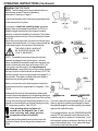
OPERATING INSTRUCTIONS
This machine is intended for manual reel mower bedknife grinding
ONLY. Any use other than this may cause personal injury and void
the warranty.
To assure the quality and safety of your machine and to maintain
the warranty, you MUST use original equipment manufactures
replacement parts and have any repair work done by a qualified
professional.
ALL operators of this equipment must be thoroughly trained
BEFORE operating the equipment.
Do not used compressed air to clean grinding dust from the
machine. This dust can cause personal injury as well as damage to
the grinder.
Grinder is for indoor use ONLY. Do not powerwash grinder.
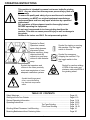
Symbols for Read
Operators manual,
wear safety glasses,
disconnect power
before servicing, sharp
objects which will
cause injury and keep
visitors a safe distance
away.
Symbol that operators and
visitors in the close proximity
must wear respirators or have
adequate ventilation systems
Symbol for starting or running
the machine. Flip the toggle
switch to this side.
Symbol for emergency
stopping the machine. Flip
the toggle switch to this
side.
Symbol for caution relating
to RPM of the motor and
minimum safe rated RPM of
the grinding wheel.
Symbol identifying a panel,
cover, or area as having
live electrical components
within.
TABLE OF CONTENTS
Safety Warnings ...................................................................................................... Page 4-6
Getting to Know Your Grinder .................................................................................. Page 6-10
General Operating Information ................................................................................. Page 11-14
Operating Instructions .............................................................................................. Page 15-20
Top Face Grinding ........................... Page 16-17
Front Face Grinding ......................... Page 18-19
Grinding Wheel Clearance, Link Mounting ............................................................... Page 14
Mounting Bedknives without Centering Holes .......................................................... Page 20
6
SPECIFICATIONS AND DAILY MAINTENANCE
SPECIFICATIONS
Electrical Requirements .................... 120V 60 Hz 13-amp or 220 VAC 50Hz 7 Amp circuit
Net Weight ................................................................................................ 230 lbs [104 kg]
Shipping Weight ........................................................................................ 250 lbs [113 kg]
Maximum Grinding Length ........................................................................ 34 in. [ 864 mm]
Sound Level ................................................................................................Less than 75 Dba
DAILY MAINTENANCE
On a daily basis, clean the grinder by wiping all areas down.
On a daily basis, inspect the grinder for loose fasteners or components and tighten.
Contact your company's Maintenance Department if damaged or defective parts are found.
DO NOT USE COMPRESSED
AIR TO CLEAN GRINDING DUST
FROM THE GRINDER.
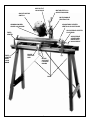
7
MOTOR TILT
LOCK KNOB
MOTOR VERTICAL
ADJUSTING KNOB
ON/OFF MOTOR
SWITCH
MOTOR ANGLE
PROTRACTOR
ADJUSTABLE CENTER
VERTICAL ADJUST KNOB
GRINDING WHEEL
GUARD LOCK KNOB
ADJUSTABLE CENTER
LOCK RING
FIXED
CENTER
ADJUSTABLE
CENTER BEDKNIFE HOLD
ADJUSTMENT
FIXED
CENTER
ASSY
LOCK
KNOB
BLADE
SUPPORT
ROD
BLADE
SUPPORT
LOCKING
KNOBS
BASE
8
GETTING TO KNOW YOUR GRINDER
OPTIONAL TOOLS
Angle Finder (optional)
Measures the mounting angles of the bedknife and the
grinding wheel motor, so they can be matched (for
proper grinding angle). Has a magnetic base.
VERTICAL
HANDWHEEL
GRIND HEAD ADJUSTMENTS
1. Vertical handwheel
Moves the grinding head up and down.
See FIG. 1
2. Horizontal Adjustment
Moves the grinding head forward and back.
See FIG. 8
GRINDING HEAD
Head Lock Lever
Allows you to pivot the complete grinding head (wheel
and motor). See FIG. 2
HEAD LOCK
LEVER
FIG. 1
THE HEAD IS HEAVY AND MUST
BE SUPPORTED WHEN THE
LOCK IS RELEASED.
Wheel Guard Lock Screws
One thumb screw which holds the guard in
position. Loosen it to pivot the guard when the
wheel orientation is changed. See FIG. 3
FIG. 2
THUMB
SCREW
FIG. 3
9
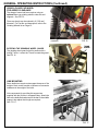
GETTING TO KNOW YOUR GRINDER (Continued)
FIXED SUPPORT
FIXED BEDKNIFE SUPPORT
Handwheel locks the center in position on the base.
See FIG. 4
FIG. 4
CENTER BEDKNIFE SUPPORT
MIDDLE SUPPORT
-
Lower Handwheel locks the center support in
position on the base. See FIG.
-
Center Support Lock Handle Bedknife in
rotational position to the grinding wheel. See FIG. 5
LOCK
HANDLE
FIG. 5
LOWER
HANDWHEEL
ADJUSTABLE BEDKNIFE SUPPORT
-
Lower Handwheel locks the Center Assy in
position on Adjustable Base. See FIG. 6
-
Side Handwheel for in/out positioning of the
center to the bedbar, with lock ring. See FIG. 6
-
Horizontal and Vertical Knobs are adjusted for
Bedknife Centers Alignment. See FIG. 6
ADJUSTABLE SUPPORT
HORIZONTAL
ADJUSTMENT
KNOB
VERTICAL
ADJUSTMENT KNOB
LOCK RING
SIDE
HANDWHEEL
LOWER
HANDWHEEL
FIG. 6
DIAMOND DRESSER
OPTIONAL Diamond Dresser allows you to dress the
grinding wheel to remove any buildup. See page 13
for more information. See FIG. 7
FIG. 7
10
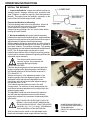
GENERAL OPERATING INFORMATION
A
WHEN TO SHARPEN THE BEDKNIFE
NOTE: To fully sharpen a reel mower, you need to grind
the reel blades (using a Reel Grinder) and reshape the
cutting edge of the bedknife (using the 384 Bedknife
Grinder).
NOTE: New bedknives should be ground before being
put into use.
When the grass is not being cut cleanly, or the cut ends
of the grass appear torn or ragged, the edges of the reel
blade and bedknife have become rounded and need
sharpening. See Fig. 8A. The purpose of sharpening is
to restore the match between the reel blades and the
cutting edge of the bedknife. See Fig. 8B.
B
FIG. 8
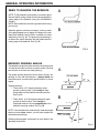
BEDKNIFE GRINDING ANGLES
The bedknife has two faces that normally need to be ground
- the top face and the front face (on some models, the front
face may be curved and not need grinding.)
A
The proper grinding angles for the two faces will vary, depending on the reel manufacturer - always follow the
manufacturers's recommended specifications for these
angles.
Typically however,
** There will be a 5-7 degree clearance angle
ground on the top face. It will usually be measured relative to the bedknife mounting surface.
See Fig. 9A.
** There will be a 10-30 degrees clearance angle
ground on the front face. It will usually be
measured relative to a line perpendicular to the
bedknife mounting surface. See Fig. 9B.
B
NOTE: If the manufacturer measures the clearance angle
relative to some other surface, you will have to adjust our
calculations accordingly.
Obtaining these angles is discussed in more detail in the
operating instructions.
Fig. 9
11
GENERAL OPERATING INFORMATION (Continued)
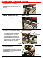
MOUNTING A GRINDING WHEEL
To replace the grinding wheel: See FIG. 10.
1. Turn the GRINDING WHEEL switch OFF.
2. Remove two of the three screws that hold the wheel
cover guard.
3. Unscrew the mounting flange that holds the grinding
wheel - use a 3/4" open-end wrench.
4. Remove the old wheel and install the new one.
5. Screws on the flange finger tight, then tighten
1/8 turn further with the wrench. It will self-tighten
when the motor is turned on.
IF THE WHEEL FLANGE IS
OVERTIGHTENED, THE GRINDING
WHEEL MAY CRACK AND EVENTUALLY
FLY APART.
FIG. 10
6. Reattach the wheel cover guard.
7. After you install a new or different wheel, we
recommend that you dress it before grinding.
See Page 10.
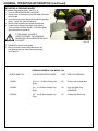
GRINDING WHEELS FOR MODEL 384
WHEEL PART NO.
COLOR/DESCRIPTION/SIZE
GRIT USE FOR GRINDING
3700067
6/4 x 1 x 1.25 Bore Flaring Cup
Ruby
60
Flaring Cup for clearance
3700265
6 x 1 x 1.25 Bore Straight Cup
Ruby
60
Finer Grit Strait Cup
STANDARD
3700266
6 x 1 x 1.25 Bore Straight Cup
Gray
46
Coarser Grit Strait Cup
12
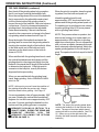
GENERAL OPERATING INFORMATION (Continued)
DRESSING THE GRINDING WHEEL
There are two methods to dress the grinding wheel, the
dressing brick which comes standard with the grinder and the
diamond dresser which is optional for the grinder. Dress the
grinding wheel whenever there is any glazing ("glazing" is the
buildup of stone dust and grinding grit on the face of the wheel).
For best results, also dress the wheel before making the final
grind.
REFER ALSO TO THE "SAFETY RULES WHEN
GRINDING" ON PAGE 5.
FIG. 11
For dressing, move the grinding head to the left hand side of the
machine as shown in FIG. 11, so you are clear of the bedknife.
Don't change the angle of the grinding head when dressing.
With the wheel spinning, use the dressing brick to dress the
face of the wheel, See FIG. 12, or with the diamond dresser,
move the grinding head and grinding wheel over the dresser
and turn the dresser adjusting screw until the diamond point
just touches the wheel. It may be necessary to loosen the
horizontal slide and move the grinding head to the diamond
dresser. See FIG. 13.
NOTE: Excessive dressing will shorten the life of the wheel.
The grinding wheel can only be dressed with the diamond
dresser in the top face grinding position.
FIG. 12
Replacing the Wheel
A new grinding wheel is 1" [25 mm] deep. When it wears down
to a depth of 0.62" [15 mm], it should be replaced. See FIG. 14.
.62 [15mm] minimum
FIG. 14
CONTROLLING TEMPERATURE
There are two suggested methods for controlling the
temperature of the grinding wheel during the grinding
process in order to avoid heat distortion and achieve
optimum results:
A. Begin by dry grinding the bedknife. Then allow the
bedknife to cool completely before doing the
final grind. NOTE: It may be necessary to wait an
hour between grinds for the bedknife to cool
completely).
B. The second method would be to use a spray bottle
with water or a wet rag or sponge to cool the
bedknife between grinding passes.
13
FIG. 13
GENERAL OPERATING INSTRUCTIONS (Continued)
USING A FLARE CUP WHEEL
FOR ADDED CLEARANCE
The shape of some bed bars requires using an
optional flare-cup grinding wheel to clear the end
supports. See FIG. 15.
Flare-cup wheels can be ordered in 6 [150 mm]
diameter. For Part No. and description, refer to the
Grinding Wheels list on Page 12.
FLARE CUP
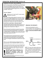
ROTATING THE GRINDING WHEEL GUARD
The grinding wheel guard is held in position with a
locking T-knob. Loosen the T-knob to rotate the guard.
See FIG. 16
FIG. 15
THUMB
SCREW
FIG. 16
LINK MOUNTING
Some bedknives require extra support because of the
weight of their center bracket or because of excessive
imbalance in the weight of the knife.
Link components for providing this support are
supplied with the Grinder in a separate bag. Attach the
links to the bedknife bracket and to the bar on the middle
support, then adjust their length as required.
See FIG. 17.
FIG. 17
14
OPERATING INSTRUCTIONS
INSTALL THE BEDKNIFE
1. Inspect the Bedknife: Inspect the bedknife and bar for
damage (cracks, warpage, bushing wear, excessive knife
wear.) Replace or repair as required. (See Manufacturer's
Manual.) Thoroughly clean the bedknife, especially on the
bottom where the middle support's will contact.
Prepare the Machine for Mounting
Pivot the grinding head to the vertical position. Move it all
the way to the left, then crank it up (so the adjustable
center stand will be easier to reposition).
Always wipe any grindings, dirt, etc. from the base before
moving the center stands.
2. Mount the bedknife: Mount the bedknife assembly
between the centers on the bedknife grinder. Adjust the blade
support bar so the top face to be ground is held at an angle of
approximately 30 degrees from horizontal plane.
With the blade at this angle, there will be very little vertical or
horizontal adjustments required as the motor is pivoted to
grind both surfaces. This position is arbitrary. The grinding
head clearance to motor base will determine final adjustments.
NOTE: The 30 degree angle may be less for some
bedknife faces that are close to the pivot mounting position,
so there will be clearance between the grinding head and the
adjustable center assembly.
FIG. 18
FIG. 19
The center stands must be locked
securely in place. Any looseness will
adversely affect grind quality.
ALIGN THE CENTERS
Place the alignment gauge onto the base and adjust the
alignment gauge so the projecting edge is touching the
top diameter and side of the fixed center as shown in
FiG. 18 and FIG. 19.
Without moving any of the adjustments made on the
alignment gauge, place the alignment gauge over the
adjustable center and adjust the adjustable center
accordingly until it is just touching the alignment gauge
top and side. See FIG. 20.
Your bedknife mounting holes are now in line with
carriage travel. For accuracy of setup always adjust the
vertical and horizontal adjustment so you adjust up to the
alignment gauge edge.
The adjustable center lock must be securely tightened
and the fixed and adjustable center must be securely
tightened to the base. Any looseness will adversely affect
grind quality.
DON'T FORCE THE CENTER TIGHTLY INTO THE
BEDBAR. THIS COULD DISTORT AND MISALIGN
THE ADJUSTABLE SUPPORT. LEAVE THE CENTER
LOOSE BY .005 - .015" [.15-.40mm], THEN REMOVE
THIS LOOSENESS AS EXPLAINED BELOW.
With your hand turn the center on the adjustable center
stand until the bedbar is held snugly with zero free play.
15
FIG. 20
SOME BEDKNIVES REQUIRE
EXTRA SUPPORT BECAUSE OF
THEIR IMBALANCE.
REFER TO "LINK MOUNTING" ON
PAGE 14.
OPERATING INSTRUCTIONS (Continued)
GRINDING THE TOP FACE
NOTE: The following instructions presume that you
have already studied "General Operating
Information" starting on Page 11.
Loosen the thumbscrew on the wheel guard and rotate
to the rear and lock in place.
If you want to match the exsisting angle, place the
Angle Finder on the bedknife as shown in FIG. 21A.
Read the angle indicated on the magnetic bubble
indicator to which the bedknife is mounted. Then place
the bubble indicator on top of the motorhead as shown
in FIG. 22.
Adjust the motor head until it is positioned at the same
angle as the bedknife face. You have now matched the
motorhead angle to the top face of the bedknife.
FIG. 23
THE HEAD IS HEAVY AND MUST
BE SUPPORTED WHEN THE
LOCK IS RELEASED.
NOTE: The bedknife may have been excessively
adjusted and lapped since its last grind. In these
cases, establish the bedknife angle from the small top
surface outside the wear area as shown in FIG. 21A.
If you want to set the angle to the manufacturer's
specifications, measure the mounting surface angle at
the top or bottom of the bedknife as shown in FIG. 21B
and then get the correct working angle from page 21 of
this manual. Then add or subtract the relief angle to
determine the grinding wheel angle.
FIG. 21
When you have the motor head angle set, adjust the
motorhead protractor angle scale to 0 degrees. See
FIG. 24.
Handcrank the vertical feed adjustment knobs and
move the horizontal adjustment until grinding wheel just
touches the face of the bedknife and covers the surface
FIG. 22
to be ground. At this point the grinding wheel rim is to If you don't have the optional angle finder, you will
extend over the bedknife top surface being ground by have to adjust the grinding head angle to match
1/2" whenever possible. See FIG. 23.
the bedknife angle by visually matching the wheel
angle to the bedknife angle.
If the grinding wheel rim does not
extend over the bedknife face, it will
wear unevenly and cause grooves
For final adjustments, turn the GRINDING WHEEL
across the surface of bedknife.
switch OFF and manually touch the wheel to the
bedknife top face to where it is contacting. Look
When the grinding wheel cannot extend over the
at the scratch marks to determine that they go fully
bedknife surface, dress the grinding wheel more
across the bedknife face. If not, adjust the angle
often.
of the motor head until they match.
16
OPERATING INSTRUCTIONS (Continued)
TOP FACE GRINDING (continued)
Next, back off the grinding wheel only enough so
that it is no longer touching the bedknife face.
Move the carriage down to the end of the bedknife
that is supported by the adjustable center stand
until the contact area of the grinding wheel is
beyond the end of the bedknife. See note below on
contact area. Check for clearance between the
grinding wheel, the bedbar and the adjustable
center stand assembly. If there is interference,
reposition the components or change to the flared
cup grinding wheel as described on Page 14.
Move the length of the bedknife and watch the
grinding head to ensure that the grinding wheel is
traveling the complete length of the bedknife. Move
to the fixed center end of the knife and verify
clearance as the head comes of the knife as
shown in FIG. 25.
When the grind is complete, dress the grinding wheel, cool the knife and spark out.
Infeed the grinding head for only
approximately .002" stock removal in final
passes and let the grinding wheel spark out.
For sparking out in grinding process, always
traverse grinding head 10 or more passes
with no grinding head infeed.
NOTE: This process refers to sparkout, but
what we are looking for is a near spark out,
approximately a 99% reduction in grinding
spark from normal grind. Do not run sparkout
until you have no sparks, because this could
be an extremely extended period. Watch the
sparks grinding pattern for the full length of
grind. The sparks should look equal for the full
length.
When satisfied with the grinding head travel, crank
the vertical feed adjustment knob down until the
grinding wheel is removing metal lightly from the
bedknife. Now travel the full length of the bedknife
to determine the high point. If the high point is
excessive to the low point, reverify the centers
alignment before proceeding.
When you are satisfied with the grinding head
travel, begin grinding. Set the GRINDING WHEEL
switch at ON.
FIG. 24
NOTE: At this point you won't know the condition of
the grinding wheel after the previous job. Always
dress the wheel before grinding. See Page 13.
It is recommended to take off approximately .002"
per pass. Rotating the vertical feed handwheel 7
degrees of a turn will remove approximately .002"
per pass. Continue grinding the bedknife in this
manner until the grinding process is complete.
BEDKNIFE COOLING IS CRITICAL TO A
QUALITY GRIND. DURING THE GRIND AND
SPARKOUT PROCESS, COOL THE
BEDKNIFE FOLLOWING THE OPTIONS
LISTED ON PAGE 13.
17
FIG. 25
NOTE: The area of the grinding wheel which
contacts the bedknife is on the left side of the
motor. The area of the wheel which doesn't
contact will still be over the bedknife. See FIG.
25. (When you go to the right end of the
Grinder, the wheel traverses completely off the
bedknife.)
OPERATING INSTRUCTIONS (Continued)
GRINDING THE FRONT FACE
NOTE: On some mower bedknives, the front face is
curved and therefore may not have to be sharpened.
Reposition the Head for Front-Face Grinding
Set the head angle protractor to zero (if not already at
zero) after the top face is ground. Then pivot the grinding
head so it is in position to grind the front face. Move the
grinding head to the right end of the carriage (beyond the
end of the bedknife). See FIG. 26. Loosen the grinding
head lock lever and rotate the head to the manufacturer's
angle specified on page 21 using the head angle protractor. See FIG. 27.
THE HEAD IS HEAVY AND MUST BE SUPPORTED WHEN THE LOCK LEVER IS
RELEASED.
FIG. 26
Reset the wheel guard as shown by loosening the
T-knobs and swinging the guard around 180 degrees
so the wheel can grind the front face of the bedknife.
See FIG. 16.
If you want to match the exsisting angle, place the
Angle Finder on the bedknife. Read the angle indicated on the magnetic bubble indicator to which the
bedknife is mounted. Then place the bubble indicator
on end of the motorhead. Adjust the motor head until
it is positioned at the same angle as the bedknife
face. You have now matched the motorhead angle to
the top face of the bedknife.
THE HEAD IS HEAVY AND MUST BE
SUPPORTED WHEN THE LOCK LEVER
IS RELEASED.
If you don't have the optional angle finder, you will have
to adjust the grinding head angle to match the
bedknife angle by visually matching the wheel angle to
the bedknife angle.
For final adjustments, turn the GRINDING WHEEL
switch OFF and manually touch the wheel to the
bedknife top face to where it is contacting. Look at
the scratch marks to determine that they go fully
across the bedknife face. If not, adjust the angle of the
motor head until they match.
18
FIG. 27
OPERATING INSTRUCTIONS (Continued)
GRINDING THE FRONT FACE (Continued)
Hand crank the vertical feed adjustment knobs and move
the horizontal adjustment until grinding wheel just touches
the face of the bedknife and covers the surface to be
ground. At this point the grinding wheel rim is to extend
over the bedknife surface being ground by 1/2" whenever
possible. See FIG. 28.
Grind the Bedknife
REFER ALSO TO THE "SAFETY RULES WHEN
GRINDING" ON PAGE 5.
Next, back off the grinding wheel only enough so that it is
no longer touching the bedknife face. Move the carriage
down to the end of the bedknife that is supported by the
adjustable center stand until the contact area of the
grinding wheel is beyond the end of the bedknife. See
note below on contact area. Check for clearance
between the grinding wheel, the bedbar and the
adjustable center stand assembly. If there is interference,
reposition the components or change to the flared cup
grinding wheel as described on Page 14.
Move the length of the bedknife and watch the grinding
head to ensure that the grinding wheel is traveling the
complete length of the bedknife. Move to the fixed center
end of the knife and verify clearance as the head comes
of the knife as shown in FIG. 29.
FIG. 28
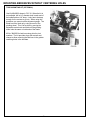
REMOVING THE BEDKNIFE
Screw back the adjustable centers.
If the next bedknife is the same length, just
mount it and screw out the adjustable center to
secure it. Don't move the adjustable (right)
support unless the next bedknife is a different
length.
When satisfied with the grinding head travel, crank the
vertical feed adjustment knob down until the grinding
wheel is removing metal lightly from the bedknife. Now
travel the full length of the bedknife to determine the high
point.
When you are satisfied with the grinding head travel,
begin grinding. Set the GRINDING WHEEL switch at ON.
FIG. 29
Crank the head until the wheel is removing metal lightly from
the bedknife. We recommend taking off about .002 to .003"
[.05 to .075 mm] per pass. When the head is horizontal,
NOTE: The area of the grinding wheel which
rotating the horizontal handwheel 7 degrees will remove
contacts the bedknife is on the left side of the
about .002 per pass.
motor. The area of the wheel which doesn't
BEDKNIFE COOLING IS CRITICAL TO A
contact will still be over the bedknife. See FIG.
QUALITY GRIND. DURING THE GRIND AND
29. (When you go to the right end of the
SPARKOUT PROCESS, COOL THE
Grinder, the wheel traverses completely off the
BEDKNIFE FOLLOWING THE OPTIONS
bedknife.)
LISTED ON PAGE 13.
Continue grinding the bedknife in this manner until you are
satisfied with the front face grind.
19
MOUNTING BEDKNIVES WITHOUT CENTERING HOLES
TORO MOUNTING KIT (OPTIONAL)
Use Kit #3840553 shown in FIG. 30. When the kit is
not available, drill a 1/4" diameter hole in each end of
the bedknife about 1/4" deep. It only has to be deep
enough for the centers to go into. When using this
procedure you cannot use the alignment gauge. The
blade has to be lined up by using a corner of the
grinding wheel. This is to be done by moving the
adjustable center back and forth until the grinding
wheel rubs the same on both ends of the blade.
Kit No. 3840553 for bed bars using slots for pivot
washers. The kit provides slugs with centers and
clamps to allow mounting the bed bars in the grinder
centering holes in the bed bars.
FIG. 30
20
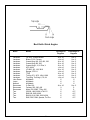
Bed Knife Grind Angles
Make
Model
Jacobsen
Jacobsen
Jacobsen
Jacobsen
Jacobsen
Jacobsen
Jacobsen
Jacobsen
Jacobsen
Jacobsen
Jacobsen
John Deere
Lesco
National
Ransomes
Ransomes
Ransomes
Toro
Toro
Toro
Toro
19” & 22” Greens Mower
Blitzer, F133, Fairway
Greens King 418, 518, 422, 522
Greens King 426, 526
Greens King II, IV, IV Plus, V
HFS, HM11
LF1000, 123, 128, 3810
Ranger, ST5111
TF60
Tri King 671, 1672, 1684, 1900
Trim King, Turf King II, 76, 84
All Models
All Models
All Models
G-Plex 160
Fairway, 250, 305, 405
Motor 180, 350D, T-Plex 185
GR500, 1000, 3000, HTM 175
RM5100, 5300, 6500
RM108, 216, 2300, 3500, 4500
RM5, RM7, RMII, Spartan, Turf Pro
21
Top Angle in
Degrees
Front Angle in
Degrees
-8 to -10
+4 to +6
-8 to -10
-8 to -10
-8 to -10
+4 to +6
-8 to -10
+4 to +6
-8 to -10
+4 to +6
+4 to +6
-5
-6
-5
-8 to -10
-3
-3
-5
-5
-5
-5
0 to -5
0 to -5
0 to -5
0 to -5
0 to -5
0 to -5
0 to -5
0 to -5
0 to -5
0 to -5
0 to -5
-5
-5
-5
0 to -5
0
0
-15**
-15**
-15**
-15**