1
®
Concerning Copyright
The law prohibits the unauthorized recording, public performance, broadcast, sale,
or distribution etc. of a work (CD recording, video recording, broadcast, etc.) whose
copyright is owned by a third party. Roland will take no responsibility for any
infringement of copyright that you may commit in using the VS-880EX.
SCMS (Appendices p. 124)
OWNER'S MANUAL
About SCMS
The VS-880EX does not implement SCMS. This design decision was made with the
intent that SCMS should not restrict the creation of original compositions which do
not violate copyright law. Do not use this device in a way which would infringe on
copyrights held by another.
Roland will take no responsibility for any “direct damages,” “consequential damages,” or “any other damages” which may result from your use of the VS-880EX.
These damages may include but are not limited to the following events which can
occur when using the VS-880EX.
● Any loss of profit that may occur to you
● Permanent loss of your music or data
● Inability to continue using the VS-880EX itself or a connected device
About the License Agreement
The VS-880EX and its CD-R capability are designed to allow you to reproduce
material to which you have copyright, or material which the copyright owner has
granted you permission to copy. Accordingly, reproduction of music CDs or other
copyrighted material without the permission of the copyright owner, other than for
your own personal use and enjoyment (private use) constitutes copyright infringement, which may incur penalties. Consult a copyright specialist or special publications for more detailed information on obtaining such permission from copyright
holders.
* Microsoft and Windows are registered trademarks of Microsoft Corporation.
Before using this unit, carefully read the sections entitled: “IMPORTANT SAFETY INSTRUCTIONS” (p. 2), “USING THE UNIT SAFELY” (p.
3, 4), and “IMPORTANT NOTES” (p. 5). These sections provide important
information concerning the proper operation of the unit. Additionally, in
order to feel assured that you have gained a good grasp of every feature
provided by your new unit, Quick Start, Owner’s Manual, and Appendices
should be read in its entirety. The manual should be saved and kept on
hand as a convenient reference.
* Windows® 95 is known officially as: “Microsoft® Windows® 95 operating system.”
* Macintosh is a registered trademark of Apple Computer, Inc.
* Iomega is a registered trademark of Iomega Corporation.
* ZIP is a trademark of Iomega Corporation.
* Cakewalk is a registered trademark of Twelve Tone systems, Inc.
* Cakewalk Pro Audio and Cakewalk Professional are trademarks of Twelve Tone systems, Inc.
* All product names mentioned in this document are trademarks or registered trademarks of their respective owners.
01562867
OWNER'S MANUAL
Disclaimer of liability
'99-3-E3-41N
Copyright © 1998 ROLAND CORPORATION
All rights reserved. No part of this publication may be reproduced in any form
without the written permission of ROLAND CORPORATION.
Roland Homepage http://www.rolandcorp.com/
CAUTION
RISK OF ELECTRIC SHOCK
DO NOT OPEN
ATTENTION: RISQUE DE CHOC ELECTRIQUE NE PAS OUVRIR
CAUTION: TO REDUCE THE RISK OF ELECTRIC SHOCK,
DO NOT REMOVE COVER (OR BACK).
NO USER-SERVICEABLE PARTS INSIDE.
REFER SERVICING TO QUALIFIED SERVICE PERSONNEL.
The lightning flash with arrowhead symbol, within an
equilateral triangle, is intended to alert the user to the
presence of uninsulated “dangerous voltage” within the
product’s enclosure that may be of sufficient magnitude to
constitute a risk of electric shock to persons.
The exclamation point within an equilateral triangle is
intended to alert the user to the presence of important
operating and maintenance (servicing) instructions in the
literature accompanying the product.
INSTRUCTIONS PERTAINING TO A RISK OF FIRE, ELECTRIC SHOCK, OR INJURY TO PERSONS.
IMPORTANT SAFETY INSTRUCTIONS
SAVE THESE INSTRUCTIONS
WARNING - When using electric products, basic precautions should always be followed, including the following:
1. Read all the instructions before using the product.
2. Do not use this product near water — for example, near a
bathtub, washbowl, kitchen sink, in a wet basement, or near
a swimming pool, or the like.
3. This product should be used only with a cart or stand that is
recommended by the manufacturer.
4. This product, either alone or in combination with an amplifier
and headphones or speakers, may be capable of producing
sound levels that could cause permanent hearing loss. Do
not operate for a long period of time at a high volume level
or at a level that is uncomfortable. If you experience any
hearing loss or ringing in the ears, you should consult an
audiologist.
5. The product should be located so that its location or position
does not interfere with its proper ventilation.
6. The product should be located away from heat sources such
as radiators, heat registers, or other products that produce
heat.
7. The product should be connected to a power supply only of
the type described in the operating instructions or as marked
on the product.
8. The power-supply cord of the product should be unplugged
from the outlet when left unused for a long period of time.
9. Care should be taken so that objects do not fall and liquids
are not spilled into the enclosure through openings.
10.The product should be serviced by qualified service
personnel when:
A. The power-supply cord or the plug has been damaged; or
B. Objects have fallen, or liquid has been spilled into the
product; or
C. The product has been exposed to rain; or
D. The product does not appear to operate normally or
exhibits a marked change in performance; or
E. The product has been dropped, or the enclosure
damaged.
11.Do not attempt to service the product beyond that described
in the user-maintenance instructions. All other servicing
should be referred to qualified service personnel.
For EU Countries
This product complies with the requirements of European Directives EMC 89/336/EEC and LVD 73/23/EEC.
For the USA
FEDERAL COMMUNICATIONS COMMISSION
RADIO FREQUENCY INTERFERENCE STATEMENT
This equipment has been tested and found to comply with the limits for a Class B digital device, pursuant to Part 15 of the
FCC Rules. These limits are designed to provide reasonable protection against harmful interference in a residential
installation. This equipment generates, uses, and can radiate radio frequency energy and, if not installed and used in
accordance with the instructions, may cause harmful interference to radio communications. However, there is no guarantee
that interference will not occur in a particular installation. If this equipment does cause harmful interference to radio or
television reception, which can be determined by turning the equipment off and on, the user is encouraged to try to correct the
interference by one or more of the following measures:
– Reorient or relocate the receiving antenna.
– Increase the separation between the equipment and receiver.
– Connect the equipment into an outlet on a circuit different from that to which the receiver is connected.
– Consult the dealer or an experienced radio/TV technician for help.
Unauthorized changes or modification to this system can void the users authority to operate this equipment.
This equipment requires shielded interface cables in order to meet FCC class B Limit.
For Canada
NOTICE
This Class B digital apparatus meets all requirements of the Canadian Interference-Causing Equipment Regulations.
AVIS
Cet appareil numérique de la classe B respecte toutes les exigences du Règlement sur le matériel brouilleur du Canada.
For the USA
GROUNDING INSTRUCTIONS
This product must be grounded. If it should malfunction or breakdown, grounding provides a path of least resistance for
electric current to reduce the risk of electric shock.
This product is equipped with a cord having an equipment-grounding conductor and a grounding plug. The plug must be
plugged into an appropriate outlet that is properly installed and grounded in accordance with all local codes and ordinances.
DANGER: Improper connection of the equipment-grounding conductor can result in a risk of electric shock. Check with a
qualified electrician or serviceman if you are in doubt as to whether the product is properly grounded.
Do not modify the plug provided with the product — if it will not fit the outlet, have a proper outlet installed by a qualified
electrician.
For the U.K.
WARNING:
THIS APPARATUS MUST BE EARTHED
IMPORTANT: THE WIRES IN THIS MAINS LEAD ARE COLOURED IN ACCORDANCE WITH THE FOLLOWING CODE.
GREEN-AND-YELLOW: EARTH, BLUE: NEUTRAL, BROWN: LIVE
As the colours of the wires in the mains lead of this apparatus may not correspond with the coloured markings identifying
the terminals in your plug, proceed as follows:
The wire which is coloured GREEN-AND-YELLOW must be connected to the terminal in the plug which is marked by the
letter E or by the safety earth symbol or coloured GREEN or GREEN-AND-YELLOW.
The wire which is coloured BLUE must be connected to the terminal which is marked with the letter N or coloured BLACK.
The wire which is coloured BROWN must be connected to the terminal which is marked with the letter L or coloured RED.
The product which is equipped with a THREE WIRE GROUNDING TYPE LINE PLUG must be grounded.
2
191
USING THE UNIT SAFELY
Used for instructions intended to alert
the user to the risk of death or severe
injury should the unit be used
improperly.
Used for instructions intended to alert
the user to the risk of injury or material
damage should the unit be used
improperly.
* Material damage refers
other adverse effects
respect to the home
furnishings, as well
animals or pets.
to damage or
caused with
and all its
to domestic
• Before using this unit, make sure to read the instructions below, and the Owner’s Manual.
...........................................................................................................
• Do not open or perform any internal modifications
on the unit. (The only exception would be where
this manual provides specific instructions which
should be followed in order to put in place userinstallable options; see Quick Start p. 49.)
...........................................................................................................
• Make sure you always have the unit placed so it is
level and sure to remain stable. Never place it on
stands that could wobble, or on inclined surfaces.
...........................................................................................................
• Avoid damaging the power cord. Do not bend it
excessively, step on it, place heavy objects on it, etc.
A damaged cord can easily become a shock or fire
hazard. Never use a power cord after it has been
damaged.
...........................................................................................................
The
symbol alerts the user to important instructions
or warnings.The specific meaning of the symbol is
determined by the design contained within the
triangle. In the case of the symbol at left, it is used for
general cautions, warnings, or alerts to danger.
The
symbol alerts the user to items that must never
be carried out (are forbidden). The specific thing that
must not be done is indicated by the design contained
within the circle. In the case of the symbol at left, it
means that the unit must never be disassembled.
The ● symbol alerts the user to things that must be
carried out. The specific thing that must be done is
indicated by the design contained within the circle. In
the case of the symbol at left, it means that the powercord plug must be unplugged from the outlet.
• Do not force the unit’s power-supply cord to share
an outlet with an unreasonable number of other
devices. Be especially careful when using extension
cords—the total power used by all devices you have
connected to the extension cord’s outlet must never
exceed the power rating (watts/amperes) for the
extension cord. Excessive loads can cause the insulation on the cord to heat up and eventually melt
through.
...........................................................................................................
• Before using the unit in a foreign country, consult
with your retailer, the nearest Roland Service
Center, or an authorized Roland distributor, as listed on the “Information” page.
...........................................................................................................
• Always turn the unit off and unplug the power cord
before attempting installation of the Hard disk drive
unit (HDP88 series: Quick Start p. 49).
• In households with small children, an adult should
provide supervision until the child is capable of following all the rules essential for the safe operation
of the unit.
...........................................................................................................
• Protect the unit from strong impact.
(Do not drop it!)
3
USING THE UNIT SAFELY
• Always grasp only the plug on the power-supply
cord when plugging into, or unplugging from, an
outlet or this unit.
...........................................................................................................
• Try to prevent cords and cables from becoming
entangled. Also, all cords and cables should be
placed so they are out of the reach of children.
...........................................................................................................
• Never climb on top of, nor place heavy objects on
the unit.
...........................................................................................................
• Never handle the power cord or its plugs with wet
hands when plugging into, or unplugging from, an
outlet or this unit.
...........................................................................................................
• Before moving the unit, disconnect the power plug
from the outlet, and pull out all cords from external
devices.
...........................................................................................................
• Before cleaning the unit, turn off the power and
unplug the power cord from the outlet (p. 33).
...........................................................................................................
• Whenever you suspect the possibility of lightning in
your area, pull the plug on the power cord out of
the outlet.
...........................................................................................................
• When installing the Hard disk drive unit (HDP88
series), remove only the specified screws (Quick
Start p. 49).
...........................................................................................................
• If you use the optical connector, be sure that the
connector cover you removed is placed out of the
reach of children.
4
IMPORTANT NOTES
In addition to the items listed under “IMPORTANT
SAFETY INSTRUCTIONS” and “USING THE UNIT
SAFELY” on pages 2–4, please read and observe the
following:
Power Supply
● Do not use this unit on the same power circuit with
any device that will generate line noise (such as an
electric motor or variable lighting system).
● Before connecting this unit to other devices, turn off
the power to all units. This will help prevent malfunctions and/or damage to speakers or other
devices.
Placement
● Using the unit near power amplifiers (or other
equipment containing large power transformers)
may induce hum. To alleviate the problem, change
the orientation of this unit; or move it farther away
from the source of interference.
● This device may interfere with radio and television
reception. Do not use this device in the vicinity of
such receivers.
● Do not expose the unit to direct sunlight, place it
near devices that radiate heat, leave it inside an
enclosed vehicle, or otherwise subject it to temperature extremes. Excessive heat can deform or discolor the unit.
Maintenance
● For everyday cleaning wipe the unit with a soft, dry
cloth or one that has been slightly dampened with
water. To remove stubborn dirt, use a cloth impregnated with a mild, non-abrasive detergent.
Afterwards, be sure to wipe the unit thoroughly
with a soft, dry cloth.
● Never use benzine, thinners, alcohol or solvents of
any kind, to avoid the possibility of discoloration
and/or deformation.
Repairs and Data
● Please be aware that all data contained in the unit’s
memory may be lost when the unit is sent for
repairs. Important data should always be backed up
on a storage device (e.g., hard disk or Zip disk) or
DAT recorder, or written down on paper (when
possible). During repairs, due care is taken to avoid
the loss of data. However, in certain cases (such as
when circuitry related to memory itself is out of
order), we regret that it may not be possible to
restore the data, and Roland assumes no liability
concerning such loss of data.
Additional Precautions
● Please be aware that the contents of memory can be
irretrievably lost as a result of a malfunction, or the
improper operation of the unit. To protect yourself
against the risk of loosing important data, we recommend that you periodically save a backup copy
of important data you have stored in the unit’s
memory on a storage device (e.g., hard disk or Zip
disk), or DAT recorder.
● Unfortunately, it may be impossible to restore the
contents of data that was stored on a storage device
(e.g., hard disk or Zip disk), or DAT recorder once it
has been lost. Roland Corporation assumes no liability concerning such loss of data.
● Use a reasonable amount of care when using the
unit’s buttons, sliders, or other controls; and when
using its jacks and connectors. Rough handling can
lead to malfunctions.
● Never strike or apply strong pressure to the display.
● A small amount of noise may be heard from the display during normal operation.
● When connecting / disconnecting all cables, grasp
the connector itself—never pull on the cable. This
way you will avoid causing shorts, or damage to the
cable’s internal elements.
● A small amount of heat will radiate from the unit
during normal operation.
● To avoid disturbing your neighbors, try to keep the
unit’s volume at reasonable levels. You may prefer
to use headphones, so you do not need to be concerned about those around you (especially when it
is late at night).
● When you need to transport the unit, package it in
the box (including padding) that it came in, if possible. Otherwise, you will need to use equivalent
packaging materials.
If an internal IDE hard disk (HDP88 series) is
installed, then remove the hard disk. Place the hard
disk in its carton and set this in the specified place
inside the VS-880EX shipping carton. The unit is
now ready to be transported. Moving the VS-880EX
with the hard disk installed may result in loss of
song data or damage to the hard disk.
5
IMPORTANT NOTES
Handling the Disk Drive
Concerning Copyright
For details on hard disk handling, refer also to the
instructions that accompanied your hard disk.
The law prohibits the unauthorized recording, public
performance, broadcast, sale, or distribution etc. of a
work (CD recording, video recording, broadcast, etc.)
whose copyright is owned by a third party.
● Before performing any of the following actions, be
sure to perform the shutdown procedure. Failure to
do so may result in loss of song data or damage to
the hard disk.
• Turning off the power of the VS-880EX
• Turning off the power of the Zip drive connected
with SCSI connector
About SCMS
• Removing a disk from a Zip drive connected with
SCSI connector
The VS-880EX does not implement SCMS. This design
decision was made with the intent that SCMS should
not restrict the creation of original compositions which
do not violate copyright law. Do not use this device in
a way which would infringe on copyrights held by
another.
Shutdown (Appendices p. 124)
When the VS-880EX MIDI/DISK indicator or Zip
drive status indicator is lit, it means that data is being
written to or from the hard disk. If you are using a Zip
drive, confirm that this indicator is not lit before
removing disks.
● While using the VS-880EX, be careful not to subject
the unit to vibration or shock, and avoid moving the
unit while the power is turned on.
● Install the unit on a solid, level surface in an area
free from vibration. If the unit must be installed at
an angle, be sure the installation does not exceed
the permissible range.
● Avoid using the unit immediately after it has been
moved to a location with a level of humidity that is
greatly different than its former location. Rapid
changes in the environment can cause condensation
to form inside the drive, which will adversely affect
the operation of the drive and/or damage removable disks. When the unit has been moved, allow it
to become accustomed to the new environment
(allow a few hours) before operating it.
6
Roland will take no responsibility for any infringement of copyright that you may commit in using the
VS-880EX.
SCMS (Appendices p. 124)
Disclaimer of Liability
Roland will take no responsibility for any direct damages, consequential damages, or any other damages
which may result from your use of the VS-880EX.
These damages may include but are not limited to the
following events which can occur when using the VS880EX.
● Any loss of profit that may occur to you.
● Permanent loss of your music or data.
● Inability to continue using the VS-880EX itself or a
connected device.
About the License Agreement
The VS-880EX and its CD-R capability are designed to
allow you to reproduce material to which you have
copyright, or material which the copyright owner has
granted you permission to copy. Accordingly, reproduction of music CDs or other copyrighted material
without the permission of the copyright owner, other
than for your own personal use and enjoyment (private use) constitutes copyright infringement, which
may incur penalties. Consult a copyright specialist or
special publications for more detailed information on
obtaining such permission from copyright holders.
CONTENTS
Preparations .......................................................................... 12
About the Package Contents ...................................................................................... 12
Main Features ............................................................................................................. 12
Front and Rear Panels .......................................................... 14
Mixer Section .............................................................................................................. 14
Recorder Section ........................................................................................................ 16
Display section ............................................................................................................ 18
Rear Panel .................................................................................................................. 19
Chapter 1 Before You Start (VS-880EX Terminology) ........ 21
Saving and Managing Data ......................................................................................... 21
Managing Disk Contents (Partitioning) ......................................................................... 21
The Location Where a Performance is Recorded (Song) ............................................. 22
Sources, Tracks, and Channels ........................................................................................ 22
About Events ...................................................................................................................... 23
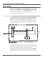
Mixer Section .............................................................................................................. 24
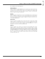
Signal Flow (Buses) ........................................................................................................... 24
Input Mixer ......................................................................................................................... 26
Track Mixer ......................................................................................................................... 27
Effect Return Mixer ........................................................................................................... 27
Switching the Fader Functions ........................................................................................ 28
Master Block ....................................................................................................................... 28
Recorder Section ........................................................................................................ 28
Differences with a Tape-Type MTR ................................................................................ 28
Track Minutes and Recording Time ............................................................................... 29
Auxiliary Tracks for Each Track ...................................................................................... 30
Effects Section ............................................................................................................ 31
About the Effect Expansion Board .................................................................................. 31
Connecting Effects ............................................................................................................. 31
Chapter 2 Basic Operation ................................................... 32
Before You Begin ........................................................................................................ 32
Turning On the Power ...................................................................................................... 32
If You Have Trouble Understanding Displays or Operations .................................... 32
Before You Finish Operations ..................................................................................... 32
Saving the Performance to Disk (Song Store) ................................................................ 32
Turning Off the Power ...................................................................................................... 33
Restarting ............................................................................................................................ 33
Basic Operations on the VS-880EX ............................................................................ 34
Display Each of the Condition Menus ............................................................................ 34
Selecting Pages Contained in Functions and Settings .................................................. 34
Select the Setting You Want to Change .......................................................................... 35
Change the Settings Values .............................................................................................. 35
Execute the Operation ....................................................................................................... 35
Switching Track Conditions ......................................................................................... 35
Changing the Current Time ......................................................................................... 36
Moving in Frame Units ..................................................................................................... 36
Moving in Measure/Beat Units ....................................................................................... 36
Moving to the Beginning or End of the Performance .................................................. 36
Storing a Time Location .............................................................................................. 36
Using the Locator ............................................................................................................... 37
Using Markers .................................................................................................................... 38
Chapter 3 Multi-Track Recording ......................................... 40
Recording .................................................................................................................... 40
Items Necessary for Multi-Track Recording .................................................................. 40
Creating a New Song (Song New) .................................................................................. 40
7
CONTENTS
General Course of the Recording Process ................................................................. 41
Connecting Instruments .............................................................................................. 41
Recording to the Tracks .............................................................................................. 42
Saving a Recorded Performance (Song Store) ........................................................... 43
Recording Over a Portion of a Performance (Punch-In/Punch-Out) ........................... 44
Using the RECORD Button (Manual Punch-In 1) ......................................................... 44
Using the Foot switch (Manual Punch-In 2) .................................................................. 44
Specifying Beforehand the Location for Rerecording (Auto Punch-In) .................... 45
Repeatedly Recording Over the Same Area (Loop Recording) .................................. 47
Recording to Other Tracks (Overdubbing) .................................................................. 49
Recording on V-Track 2 .................................................................................................... 49
Using Effects ............................................................................................................... 50
Applying Effects to the Playback .................................................................................... 50
Applying Effects While Recording (Send/Return) ...................................................... 51
Applying Effects While Recording (Insert) .................................................................... 52
Recording Digital Signals ............................................................................................ 55
Items Necessary for Digital Recording ........................................................................... 55
Make the Digital Connections ......................................................................................... 55
Match the Sample Rates .................................................................................................... 55
Select the Master Clock ..................................................................................................... 56
Select an Input Source ....................................................................................................... 56
Adjusting the Tone (Equalizer) .................................................................................... 57
Using the 3-Band Equalizer .............................................................................................. 57
Adjusting the Equalizer .................................................................................................... 57
Combining the Contents of Tracks (Track Bouncing) ................................................. 60
Applying Reverb While Track Bouncing ....................................................................... 61
Creating a Master Tape .............................................................................................. 63
To Record to a Cassette Tape ........................................................................................... 63
Recording with DAT and MD Recorders ....................................................................... 63
Protecting Songs (Song Protect) ................................................................................. 64
Protecting Performances ................................................................................................... 65
To Remove Song Protect ................................................................................................... 65
Selecting a Song (Song Select) .................................................................................. 65
Chapter 4 Using the Internal Effects ................................... 66
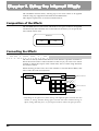
Composition of the Effects .......................................................................................... 66
Connecting the Effects ................................................................................................ 66
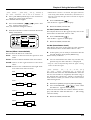
Changing the Source Sound Itself (Insert) ..................................................................... 66
Inserting with Input and Track Channels ...................................................................... 67
Inserting an Effect into the Master Block ....................................................................... 67
Adding the Sound with the Effect Applied to the Direct Sound (Send/Return) ..... 68
Selecting Effects (Patch) ............................................................................................. 70
Creating New Effects Sounds ..................................................................................... 71
When Saving to User Patches .......................................................................................... 72
When Storing to a Scene ................................................................................................... 72
Chapter 5 Storing Mixer Settings ......................................... 73
Recording the Current Condition of the Mixer (Scene) ............................................... 73
Making Mixer Settings Automatically(EZ Routing) ...................................................... 74
Recalling Recording Settings (Recording/Template) .................................................. 75
Recalling Track Bouncing Settings (Bouncing/Template) .......................................... 75
Recalling Mixdown Settings (Mixdown/Template) .................................................... 76
Storing Recording Settings (Recording/Step Edit) ...................................................... 77
Storing Track Bouncing Settings (Bouncing/Step Edit) .............................................. 81
Storing Mixdown Settings (Mixdown/Step Edit) ........................................................ 84
Saving the Current Routing (User Routing) .................................................................. 87
Recalling User Routing ..................................................................................................... 87
Deleting User Routings ..................................................................................................... 87
8
CONTENTS
Chapter 6 Editing a Recorded Performance (Track Editing) ... 88
About Editing Operations ............................................................................................ 88
Track Edit .................................................................................................................... 88
About the Bar Display ....................................................................................................... 88
Repeating Performance Data (Track Copy) ................................................................... 89
Moving Performance Data (Track Move) ...................................................................... 91
Exchanging Performance Data Between Tracks (Track Exchange) ............................ 92
Inserting a Blank Space Into Performance Data (Track Insert) ................................... 93
Deleting Performance Data (Track Cut) ......................................................................... 94
Erasing Performance Data (Track Erase) ....................................................................... 95
Modifying the Playback Time of the Performance Data
(Time Compression/Expansion) ..... 96
Chapter 7 Use with a Zip Drive ............................................ 99
Before You Use a Zip Drive ........................................................................................ 99
Handling the Zip Drive .................................................................................................... 99
Handling Zip Disks ........................................................................................................... 99
Connecting the Zip Drive ............................................................................................. 99
Initializing the Disk (Drive Initialize) ........................................................................... 100
Checking Disk Reliability ............................................................................................... 101
Saving Performance Data to a Zip Drive (Song Copy) ............................................. 102
Saving a Song to a Single Disk (Playable) ................................................................ 103
To Load Data from Disks (Drive Select) .................................................................... 104
When You Cannot Save a Song to a Single Disk (Archives) .................................... 105
Saving to Disks (Store) .................................................................................................... 105
Loading Data From Disks (Extract) .............................................................................. 106
About power-save mode ........................................................................................... 106
Chapter 8 Use with a CD-RW Drive .................................... 107
Before You Use a CD-RW Drive ............................................................................... 107
Handling the CD-RW Drive ........................................................................................... 107
Handling CD-RW Discs .................................................................................................. 107
Connecting the CD-RW Drive ................................................................................... 107
Creating an Audio CD ............................................................................................... 108
Items Necessary for Creating an Audio CD ................................................................ 108
Creating a Master Data ................................................................................................... 108
Writing Songs to CD-R Discs ......................................................................................... 109
Auditioning (Test Listening) Songs Written to CDs (CD Player Function) ............ 110
Writing Additional Songs to the Disc ........................................................................... 111
Arranging and Writing Multiple Songs to Disc .......................................................... 111
Writing the Song Data (Finalize) ................................................................................... 112
Arranging and Writing Songs and Song Data ............................................................ 113
Saving Songs to CD-RW Discs (CD-R Backup) ....................................................... 113
Items Necessary for CD-R Backup ................................................................................ 114
Saving Songs to CD-RW Discs ....................................................................................... 114
Loading Songs From CD-RW Discs .............................................................................. 115
How to Erase the Data in the CD-RW Disc ................................................................. 115
Chapter 9 Use with MIDI Devices ....................................... 116
Synchronizing with MIDI Sequencers ....................................................................... 116
Items Necessary for Synchronization ........................................................................... 116
Master and Slave .............................................................................................................. 116
Using MTC ....................................................................................................................... 116
Synchronization with the VS-880EX as the Reference (Master) ............................... 117
Synchronization with the MIDI Sequencer as the Reference (Slave) ....................... 118
Synchronizing with an External MIDI Device ............................................................ 119
Using the Sync Track (Master) ....................................................................................... 119
Using the Tempo Map (Master) .................................................................................... 121
9
CONTENTS
Various Operations Related to Synchronized Operation .......................................... 123
Use with a MIDI Controller ........................................................................................ 126
Switching Track Status ................................................................................................... 126
Switching Scenes .............................................................................................................. 127
Switching Effects .............................................................................................................. 127
Adjusting Effects .............................................................................................................. 127
Chapter 10 Use with a DAT Recorder (DAT Backup) ........ 128
Before Backing Up with DAT ..................................................................................... 128
Items Necessary for DAT Backup ............................................................................. 128
About the Devices Used in DAT Backup ..................................................................... 128
Saving Song Data to a DAT Recorder (Backup) ....................................................... 129
Loading Performance Data from a DAT Recorder (Recover) ................................... 131
When Canceling the Recover Operation ...................................................................... 132
Checking Names of Saved Performance Data (Name) ............................................ 133
Checking the Recording Condition of Saved Performance Data (Verify) .................. 134
Chapter 11 Compatibility .................................................... 136
Disk Compatibility ...................................................................................................... 136
VS-880 → VS-880EX ........................................................................................................ 136
VS-880EX → VS-880 ........................................................................................................ 136
VS-1680 → VS-880EX ...................................................................................................... 136
VS-880EX → VS-1680 ...................................................................................................... 137
VS-840 ↔ VS-880EX ........................................................................................................ 137
Song Data Compatibility ............................................................................................ 137
Loading VS-880 Performance Data into the VS-880EX (Song Import) .................... 137
Converting VS-880EX Song Data for Use with the VS-880 (Song Export) .............. 138
Chapter 12 Other Convenient Functions .......................... 140
Previewing Techniques (Preview) ............................................................................. 140
Using [TO] [FROM] ......................................................................................................... 140
Using [SCRUB] ................................................................................................................. 141
Recalling a Specific Location (Jump) ........................................................................ 142
Recording Mixer Settings (Auto Mix) ......................................................................... 142
Preparations for Auto Mix ............................................................................................. 143
Recording the Mixer Settings, Method 1 (Snapshot) .................................................. 143
Recording the Mixer Settings, Method 2 (Gradation) ................................................ 144
Recording Fader Operations (Realtime) ....................................................................... 144
If You Don’t Want to Record Fader Settings (Mask Fader) ....................................... 145
Playing Back the Auto Mix ............................................................................................. 145
Disabling Auto Mix Only on Specified Channels ....................................................... 145
Disabling Auto Mix on All Channels ........................................................................... 146
Undoing Recordings and Edits (Undo) ...................................................................... 146
Recording and Editing Operations Which Can Be Undone (Undo) ......................... 147
Canceling the Last-Performed Undo (Redo) ............................................................... 147
Canceling Only the Very Last-Performed Operation ................................................. 147
Listening Only to a Specific Channel (Solo/Mute) ..................................................... 148
Listening Only to a Specific Channel ............................................................................ 148
Muting Only to a Specific Channel ............................................................................... 148
Simultaneously Adjusting a Stereo Source (Channel Link) ....................................... 149
Adjusting the Faders ....................................................................................................... 149
Adjusting the Pan ............................................................................................................ 150
Linking Only the Faders (Fader Link) .......................................................................... 151
Mixing In a Stereo Source (Stereo In) ....................................................................... 152
Changing the Pitch During Playback (Vari-Pitch) ...................................................... 152
Record/Playback Tracks When Using Vari-Pitch ...................................................... 153
Directly Inputting Numeric Characters ...................................................................... 153
Selecting the Method for Numeric Input ..................................................................... 153
10
CONTENTS
Sounding the Metronome .......................................................................................... 154
Using an External MIDI Sound Source to Play the Metronome ............................... 155
When the Disk Has Little Remaining Space ............................................................. 156
Deleting Only Unneeded Performance Data (Song Optimize) ................................. 156
Deleting One Song of Performance Data (Song Erase) .............................................. 157
Changing the Name of Performance Data (Song Name) .......................................... 157
Adjusting the Levels for Each Track .......................................................................... 157
When Using Balanced Inputs .................................................................................... 158
Determining Output ................................................................................................... 158
MASTER Jacks ................................................................................................................. 158
AUX Jacks ......................................................................................................................... 159
DIGITAL OUT Connectors ............................................................................................ 159
DIRECT OUT ................................................................................................................... 160
Confirming That a Drive is Not Damaged (Drive Check) .......................................... 160
Chapter 13 Making Global Settings and Checking Conditions .. 163
Switching the Display Content .................................................................................. 163
Pre Level ........................................................................................................................... 163
Post Level .......................................................................................................................... 163
Play List ............................................................................................................................. 163
Feder/Pan ......................................................................................................................... 163
Checking the Size of a Recorded Performance ........................................................ 164
System Settings for Each Song ................................................................................ 164
Having the Volume Change as Soon as the Faders are Moved ................................ 164
Holding Level Meter Peaks ............................................................................................ 164
Checking the Remaining Disk Space ............................................................................ 165
When Using the Foot Switch .......................................................................................... 165
Overall Settings for the VS-880EX ............................................................................ 166
Holding the function of [SHIFT] (Shift Lock) .............................................................. 166
Displaying Measures and Beats .................................................................................... 166
Adjusting the Button Sensitivity ................................................................................... 167
Changing the VS-880EX’s SCSI ID Number ................................................................ 167
When There Is No Hard Disk Installed ........................................................................ 167
Changing at the Level at Which the Peak Indicator Lights ....................................... 168
Overall Settings for Playback and Recording ............................................................ 168
Constantly Monitoring the Input Source ..................................................................... 168
Stopping Automatically .................................................................................................. 168
If Noise Between Segments is Obtrusive ..................................................................... 169
Resetting Mixer and System Settings to Their Original State ................................... 169
Chapter 14 Takein Advantages of the VS-880EX (idea and examples) 170
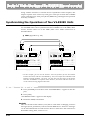
Synchronizing the Operations of Two VS-880EX Units ............................................ 170
Settings for the Master VS-880EX .................................................................................. 170
Settings for the Slave VS-880EX .................................................................................... 172
Synchronizing with Cakewalk Pro Audio (MMC) ....................................................... 173
Settings for the VS-880EX ............................................................................................... 174
Settings for Cakewalk Pro Audio .................................................................................. 175
Making Digital Connections with Cakewalk ............................................................... 177
Using an External MIDI Device to Adjust the Mixer (Compu Mix) ............................. 180
The Correspondence Between MIDI Channels and Controller Numbers .............. 181
Preparations for Compu Mix ......................................................................................... 182
Recording with Compu Mix .......................................................................................... 183
To Have the Fader Movements Ignored ...................................................................... 183
Synchronizing with Video Equipment ........................................................................ 184
Using External Effects Devices ................................................................................. 185
11
Preparations
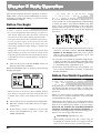
About the Package Contents
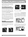
Digital Mixer Section
The following items are included with the VS-880EX.
Please check to make sure you have all the items.
You can store all mixer settings, including fader levels,
pan, and effects. Stored settings can be recalled very
simply, making it convenient in adjusting balances
during mixdown and comparing mixes with effects.
• VS-880EX
• AC cord
• Quick Start
• Owner’s Manual (this manual)
• Appendices
Changes in settings over time, such as fader levels and
pan, can also be stored (Auto Mix), so you can realize
easy fade-ins and fade-outs in your mixes.
You can easily make the most appropriate mixer condition settings, including those for recording, track
bouncing, and mixdown (EZ Routing).
Main Features
Effects Section
The Latest in Compact Home Studio
Environments
A Effect is built in. This allows you to use up to two
stereo effects when the VS-880 EX is used by itself.
The VS-880EX retains all of the features of Roland’s
VS-880 workstation; a revolution in the world of the
home studio, with the disk recorder, digital mixer, and
multi effects systematically and more organically integrated. From when you start picking mics to when
you actually record to mixdown, adding effects, and
on to creating the master data for playing through a
PA or mastering on a CD, you can get a handle on
every aspect of the recording process with the VS880EX in your home studio.
The effect provides not only basic effects such as
reverb and delay, but also effects ideal for vocals and
guitar (such as guitar amp simulator) and even special
effects such as RSS. The way in which each of these
effects are organized by the 34 “algorithms” so that
you can create new sounds easily.
Disk Recorder Section
The digital disk recorder section provides eight playback tracks, and allows eight tracks to be recorded
simultaneously. Each track has eight supplementary
tracks (V-tracks), and each song can have two sets of
these 64 tracks (8 tracks x 8 V-tracks). This means that
a song can have a total of 128 tracks (64 V-tracks x 2
banks), giving you flexibility when you need to record
multiple takes, or need a location for temporary storage for editing.
You can instantly find the location of sections in a
song you want to hear repeatedly or places that you
wish to record over (Locator) by placing marks at such
points (Marker). These Markers are recalled by simple
procedure, and you will never wait for any rewinding
or fast-forwarding time.
The VS-880EX uses “non-destructive editing.” This
allows you to cancel and recover up to 999 previous
recording and editing operations (Undo/Redo).
12
The effect provides 210 read only effects setting (Preset
Patches) which designed for various uses. In addition,
the effect provides 100 read and write effects setting
(User Patches) for changing and saving that contents.
You can instantly switch between a variety of effects
simply by selecting a patch.
Simple Operation
The VS-880EX can be operated as easily as conventional multi-track recorders. You will be able to enjoy the
advantages of home studio from the day that you purchase it.
The custom LCD screen provides visual confirmation
of many settings at once. In particular, the bar display
provides a graphical indication of the level meter, pan
and fader settings, and the track record status.
The LCD screen is backlit and inclined, so it is easy to
read when used on stage or wherever high visibility is
required.
Preparations
Connectivity
Substantial Options
There are six sets of balanced input jacks, handling a
wide input sensitivity range, from line level (+4 dBu)
to mic level (-50 dBu).
Internal Hard Disk (desinated by Roland):
Besides the RCA phono type (stereo) MASTER jacks,
the (mono) AUX A and AUX B jacks are provided.
The VS-880EX provides both coaxial and optical digital I/O connectors. With these, you can make digital
connections with popular consumer electronic devices
such as CD players, DAT recorders, MD recorders,
and so on.
A SCSI connector (DB-25 type) is also provided, allowing you to connect to external SCSI devices such as the
Zip drive and the CD-R drive.
MIDI IN and MIDI OUT/THRU connectors are also
provided. You can synchronize the VS-880EX with an
external MIDI sequencer, use the MIDI sequencer to
control the VS-880EX’s mixer, sound an external MIDI
sound generator with the metronome, and more.
Besides tracks for recording audio signals, the VS880EX has sync track for storing MIDI clock message.
You can even synchronize MIDI sequencers that are
not compatible with MTC (MIDI Time Code) or MMC
(MIDI Machine Control).
An internal 2.5-inch IDE hard disk. Having this internal hard disk installed makes the VS-880EX system
compact and easy to transport. Furthermore, there is
no need to make complex settings and no problems
with faulty connections (unlike those which could
occur when an external disk is used). We recommend
that you install an internal hard disk when using the
VS-880EX.
* For simultaneous recording or playback of a number of
tracks, for getting more out of the available hard disk
space, and in order to get the fullest performance in general from the VS-880EX, we recommend using the 2.1
GB or larger Hard Disk.
CD-R Drive (designated by Roland):
A CD-R drive connected with a SCSI connector. With
this drive, you can write songs created on the VS880EX as well as create your own original audio CDs.
Additionally, you can use it for backing up songs to
CD-R discs.
SI-80S:
This is a video/MIDI sync interface for connection to
the MIDI connector. VS-880EX operations such as
play/stop/forward can be synchronized from a video
device with a LANC connector.
13
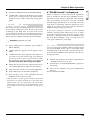
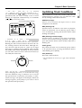
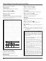
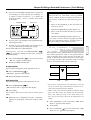
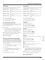
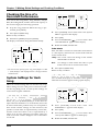
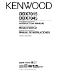
Front and Rear Panels
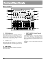
Mixer Section
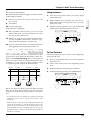
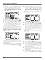
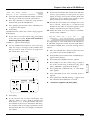
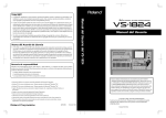
1.
1
2
7
3
8
4
9
5
10
6
11
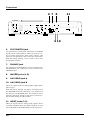
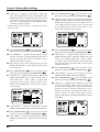
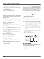
PEAK Indicators
These indicators allow you to confirm the sound level
input at the input jacks (1–6). They help you to determine the correct input level when adjusting the
INPUT knobs. You will need to specify the level at
which the indicators light beforehand (p. 61). The indicators are set at the factory to -6 dB.
2.
INPUT Knobs
These knobs adjust the sensitivity of the input jacks
(1–6). Turn a knob fully to the right for mic level (-50
dBu), and fully to the left for line level (+4 dBu).
3.
PAN Knobs
These knobs adjust the pan (location in the stereo output) of each channel.
14
4.
SELECT/CH EDIT (Select/Channel
Edit) buttons
Use these buttons when you wish to make settings for
a mixer channel. The names of the parameter groups
that can be set for each channel are printed below CH
EDIT. To directly specify a particular group, you can
hold down [SHIFT] and press the button for that
group name.
When editing a song, use these buttons to select tracks
for editing.
Preparations
5.
STATUS Buttons
These buttons switch the status of each track. The current status is shown by the button indicator.
SOURCE (orange):
The input source or track assigned to the channel is
being output.
10. FADER/EDIT Button
Pressing this button alternately assigns each channel’s
input mixer, track mixer and effect return mixer to the
fader for that channel. The button indicator shows the
current status.
INPUT (orange): Input Mixer
REC (blinking red):
TRACK (green):
Track Mixer
Recording is selected for the track assigned to the
channel. During playback, the track data is normally output.
RETURN (red):
Effect Return Mixer
In conjunction with [SHIFT], this accesses the Master
Block setting page.
REC (blinking red and orange):
Recording is selected for the track assigned to the
channel. During playback, you will be able to listen
to the source.
11. Master Fader
Use this fader to adjust the overall output level.
PLAY (green):
The track assigned to the channel will playback.
OFF (off):
The channel is muted (silent).
When pressed in combination with the SELECT/CH
EDIT button, this selects the source or track to be
assigned to a track for recording.
6.
Channel Faders
Use these faders to adjust the volume level of each
channel or track.
7.
PHONES Knob
This knob adjusts the volume of the headphones.
8.
AUX SEND knob
This knob adjusts the output level of the AUX SEND
jacks.
9.
EZ ROUTING/SOLO Button
This button opens the EZ Routing screen.
In conjunction with [SHIFT], this switches the Solo
function on/off.
15
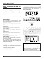
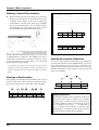
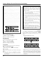
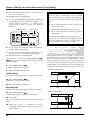
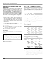
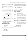
Preparations
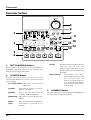
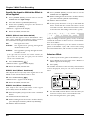
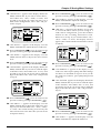
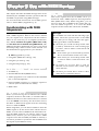
Recorder Section
5
6
7
1
9
11
2
13
8
10
12
3
4
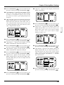
1.
EDIT CONDITION Buttons
[LOOP]:
The functions and parameters of the VS-880EX are
organized within these buttons. To use a desired operation, press the appropriate button.
2.
[AUTO PUNCH]:
LOCATOR Button
Pressing this button allows you to store or recall
Locators and Markers or to store or recall Scenes (the
mixer settings).
[LOC1/5]–[LOC4/8]: This button selects Locators
and Scenes.
[CLEAR]:
[SCENE]:
This button turns Auto
Punch-In Recording on and
off. Pressed with the
[LOC1/5]–[LOC4/8] buttons, it specifies the range to
be recorded in Auto PunchIn Recording.
This button deletes Locators,
Markers, and Scenes.
3.
This is pressed when storing,
recalling, and deleting Scenes.
Press this when you want to use the LOCATOR button
for 10-key entry of Western numerals.
[PREVIOUS]: This button recalls the previous
Marker.
[NEXT]:
This button recalls the next Marker.
[TAP]:
This button is pressed to set
Markers.
16
This button turns Loop Recording on
and off. Pressed with the
[LOC1/5]–[LOC4/8] buttons, it specifies the range to be recorded in Loop
Recording.
NUMERICS Button
Preparations
4.
Transport Control Buttons
These buttons are used to operate the recorder.
[ZERO]:
This returns the current time to
“00h00m00s00” (zero return).
[REW]:
The current time is moved back only
while this button is held down. This
corresponds to the rewind button on a
tape recorder.
[FF]:
[STOP]:
Stops recording or playback of the
song.
[PLAY]:
Starts recording or playback from the
current time.
[REC]:
5.
While the button is held down, the
current time is moved forward. This
corresponds to the fast-forward button
on a tape recorder.
Press this button to record a song.
TIME/VALUE Dial
In normal (playback) status, this dial adjusts the time
of playback.
This is used to change the settings values for each
parameter when settings are changed.
6.
PLAY (DISPLAY) Button
Press this button to return to the screen that appears
when the VS-880EX is turned on (normal playback status).
9.
CURSOR Buttons
Normally (i.e. in Play Condition), this dial is used to
move the current time. When making settings (i.e. in
Edit Condition), this dial is used to modify parameter
values.
When a YES/NO response is required during an operation, use these button to reply.
[NO (CANCEL)]: This is pressed to cancel the current operation or exit the current screen.
[YES (ENTER)]:
This is pressed to execute the
current operation or select the
current screen.
10. AUTOMIX (VARI PITCH) Button
This button switches the Auto Mix function on and off.
The button indicator lights when Auto Mix is on.
In conjunction with [SHIFT], this switches the Varipitch function on/off.
11. MIDI/DISK Indicator
This indicator lights green when MIDI messages are
being received, and red when data is being written or
read on the disk drive. If both of these are occurring,
the indicator lights orange.
12. UNDO (REDO) Button
In conjunction with [SHIFT], this switches the item
shown in the bar display.
Press this button to cancel a recording or editing step
that you have made (Undo function). Pressed with
[SHIFT], this button cancels the last performed Undo
function (Redo function).
7.
13. PREVIEW Button
PARAMETER Buttons
Use these buttons to switch the parameter display.
8.
SHIFT Button
Press this button to use the Preview function that
plays back a specific length before and after the current location.
This button is pressed in conjunction with other buttons to access additional functions of those buttons.
17
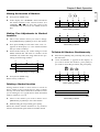
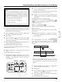
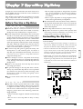
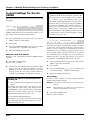
Preparations
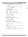
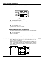
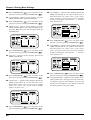
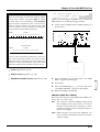
Display section
1
2
4
5
6
7
3
8
9
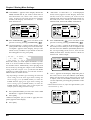
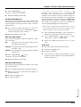
1.
CONDITION
This indicates the current condition.
PLY: Normal status (Play condition).
INn: Change the input mixer settings
(n=1–8, a–d).
4.
MEASURE
This shows the current measure of the song.
5.
BEAT
This shows the current beat of the song.
TRn: Change the track mixer settings
(n=1–8 to a–d).
6.
RTN: Change the return mixer settings.
This indicates the current sync mode (method of synchronization).
MST: Change the master block settings.
SYNC MODE
SNG: Song edit
7.
LOC: Locator edit
This shows the currently used scene number (mixer
setting). An asterisk “✱” shown at the beginning of the
scene number indicates that the current mixer settings
have been modified since the scene was recalled.
TRK: Track edit
FX:
Effect edit
SCENE
SYS: System edit
* If Song Protect (p.64) is turned on, the Play Condition
display will be “Ply.”
* The input/track mixer display will indicate 1–8 for channels whose Channel Link is OFF, and a–d for channels
which are turned ON.
2.
MARKER # (marker number)
This shows the marker number for the current time. If
a mark point has not been assigned to the current
time, the closest marker number located before the
current time will be shown.
3.
TIME
The current time of the song is displayed as SMPTE
time code.
SMPTE Time Code (Appendices p. 124)
18
8.
REMAINING TIME
This shows the remaining length of time available for
recording.
9.
Bar display
In normal condition, the item selected by [DISPLAY
(PLAY)] are shown graphically. While you are making
a setting, data for the setting being made is displayed
graphically.
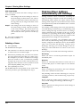
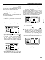
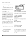
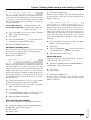
Preparations
Rear Panel
1
2
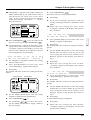
1.
3
4
POWER Switch
This switch turns power of the VS-880EX on and off.
2.
AC IN (AC Inlet)
5
5.
DIGITAL Connectors
The VS-880EX features both coaxial and optical digital
I/O connectors (conforming to S/P DIF).
IN:
This inputs a digital audio signal
(stereo). You can select either the
coaxial input connection or the optical connection.
OUT:
This outputs a digital audio signal
(stereo). Here you can use both the
coaxial connector and the optical
connector simultaneously, and each
can carry a different signal.
Connect the included power cable here.
3.
SCSI Connector
This is a DB-25 type SCSI connector for connecting
disk drives such as a Zip disk drive or a CD-R drive.
4.
MIDI Connectors (IN, OUT/THRU)
External MIDI devices (MIDI controllers, MIDI
sequencers, etc.) can be connected here.
IN:
OUT/THRU:
This connector receives MIDI messages. Connect it to the MIDI OUT
connector of the external MIDI
device.
This connector can be used either as
a MIDI OUT or as a MIDI THRU
connector. With the factory settings,
it will function as a MIDI OUT connector, which means it is set to
transmit MIDI messages.
S/P DIF (Appendices p. 124)
* To record a digital audio signal, it is not sufficient to simply connect a digital audio device to the DIGITAL IN
connector. When inputting a digital audio signal, refer to
“Recording Digital Signals” (p. 55).
* It is not able to input or output analog audio signals.
19
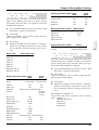
Preparations
6 7 8
9 10
6.
FOOT SWITCH Jack
An optional foot switch (such as the DP-2 or the BOSS
FS-5U) can be connected here when you want to control recorder operations, mark point settings, and
punch in/out operations, and so on with a foot switch.
With the factory settings, a foot switch is set to start
and stop the recorder.
7.
PHONES Jack
An optional set of headphones can be connected here.
The PHONES jack outputs the same sound as the
MONITOR jack.
8.
MASTER Jacks (L, R)
9.
AUX SEND Jack A
10. AUX SEND Jack B
These are output jacks for analog audio signals (RCA
phono type).
With the factory settings, all signals are output from
the MASTER OUT jacks, and there is no output from
the AUX (A and B) SEND jacks. The output is determined by the block settings of the mixer’s master section and the settings of each channel.
11. INPUT Jacks (1–6)
These are input jacks for analog audio signals. These
are balanced phone jacks, the input sensitivity of each
jack is adjusted by the INPUT knobs on the top panel.
20
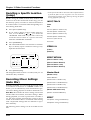
11
This chapter explains basic concepts, internal structure, and basic operation that you will need to know in
order to operate the VS-880EX. Please read this chapter thoroughly to gain a better understanding of the
VS-880EX.
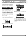
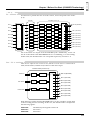
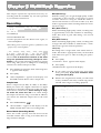
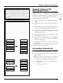
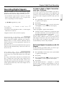
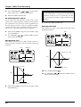
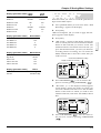
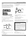
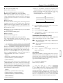
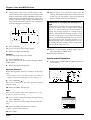
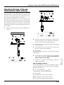
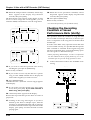
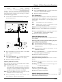
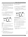
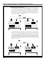
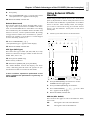
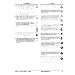
Saving and Managing Data
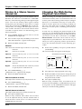
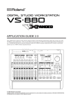
Ex. 3: When the disk drive is 2.1 GB, and the partition size is 500 MB.
Disk Drive
(2.1GB)
Partition 0
(500MB)
Partition 1
(500MB)
Partition 2
(500MB)
Partition 3
(500MB)
Managing Disk Contents (Partitioning)
The VS-880EX saves all of the data such as — performance data, mixing data, system data, etc. — on the
disk drive. Thus, it cannot operate without either having an internal disk or being connected to a Zip drive
with a SCSI connector. Furthermore, the hard disk or
Zip drive used by the VS-880EX cannot be used by
another device.
The VS-880EX is able to manage which 500 MB or 1000
MB of disk space at once. If you use a disk drive with a
capacity that is larger than this, you will need to
divide it into two or more.
Each of these area is refered as the “partition.” Up to 4
partitions can be created in one disk drive. For creating songs in a enough space, we recommend you to
set the partitions to 1000 MB.
Ex. 1: When the disk drive is 810 MB, and the partition size is 1000 MB.
Disk Drive
(810MB)
Partition
(810MB)
unusable
(100MB)
Ex. 4: When the disk drive is 2.1 GB, and the partition size is 1000 MB.
Disk Drive
(2.1GB)
Partition 0
(1000MB)
Partition 1
(1000MB)
Partition 2
(100MB)
Each partition on the VS-880EX’s disk drive is treated
as an independent drive, with each partition automatically given a partition number (0–3). When a single
hard disk has multiple partitions, you can specify
which partition of which drive will be used. This disk
drive partition currently used is referred to as the current drive.
Ex. 2: When the disk drive is 1.4 GB, and the partition size is 1000 MB.
Disk Drive
(1.4GB)
Partition 0
(1000MB)
Partition 1
(400MB)
21
Chapter 1
Chapter 1 Before You Start (VS-880EX Terminology)
Chapter 1 Before You Start (VS-880EX Terminology)
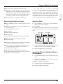
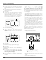
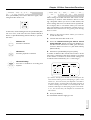
Specify the Disk Which will be Used
for Recording/Playback (Drive Select)
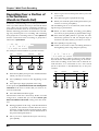
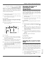
The Location Where a Performance is
Recorded (Song)
1. Press [SYSTEM] several times until “SYS Drive
Select” appears in the display.
The location where a performance data is recorded is
refered to as the song. For example on a cassette MTR,
this would correspond to cassette tape. Up to 200
songs can be created in each partition. Normally, you
should set the partition size at 1000 MB. When dealing
with large numbers of songs at the same time, setting
the partition size to 500 MB is recommended. The song
currently being recorded, played back, or edited is
referred to as the current song. Following data are
included in a song.
2. Press [YES].
3. Use the TIME/VALUE dial to select the desired
disk drive. The internal hard disk is shown as
“IDE:*” and external disk drives are shown as
“SC0:*–SC7:*” (the number is the SCSI ID number).
The number following each disk drive name is the
partition number. For example if you wish to select
internal hard disk partition 1, you would select
“IDE:1.”
4. Press [YES].
A confirmation message appears on the screen.
5. Press [YES].
“STORE Current?” (Store the current song?) appears
in the display.
6. If you wish to save the current song, press [YES]; if
not, then press [NO]. If you have selected a demo
song, then press [NO].
7. After you have switched the current drive, return
to Play condition.
* If you wish to use hard disks or song data on both the VS880EX and the VS-880/840/1680, because of factors such
as differing partition sizes and numbers of tracks, there
will be limitations as to what you can do. For more
detailed information, please see “Compatibility” (p. 136).
* The VS-880EX accepts installation of Internal hard disks
(desinated by Roland). For simultaneous recording or
playback of a number of tracks, for getting more out of the
available hard disk space, and in order to get the fullest
performance in general from the VS-880EX, we recommend using the 2.1 GB or larger Internal Hard
Disk.
22
• All data recorded on V-tracks
• MIDI clocks of the sync track
• Points specified within songs (locator, marker,
punch-in/out points, loop-in/out points) (p. 36)
• Scenes (mixer settings)
• Vari Pitch settings (p. 152)
• System settings (system, MIDI, disk, sync, Scene)
(p. 164)
• Effect settings
• Auto Mix Data
Sources, Tracks, and Channels
On the VS-880EX, the recorder section and mixer section use term sources, tracks, and channels. These
terms may appear similar to each other, and will be
confusing unless their differences are clarified.
Source:
A signal which is input to the mixer section or recorded in the recorder section.
On the VS-880EX, this term refers in particular to the signals of the analog input
jacks (1–6) and the digital in connector.
Track:
A signal that is being input to or output
from the recorder section. It also refers to
the location of a signal that is being
recorded onto or played back from the
hard disk.
Channel:
A signal that is being input to or output
from the mixer section. This term refers in
particular to the faders and buttons of the
mixer section on the top panel.
About Events
The smallest unit of memory used by the VS-880EX to
store recorded results on disk is called an event. A
newly created song is provided approximately 12,800
events.
For each track, one recording pass uses two events.
Operations such as punch-in/out or track copy also
use up events. The number of events that are used up
will fluctuate in a complex way. For example, auto
mix (p. 142) uses up 5 events for each Marker.
Even when your disk has ample free space, one song
can use up all the available events, in which case no
more data could be recorded to the song.
Remaining number of Events can be saved with the
following procedures. Please try the most appropriate
one with your situation.
● Execute Song Store (p. 32)
Please Execute Song Store if in UNDO condition
([UNDO] indicator is lit.). Events served for REDO
will be released. But please note that you cannot cancel (REDO) the last UNDO if you once execute STORE.
● Execute Song Optimize (p. 156)
Please execute Song Optimize if you have done a lot of
Punch In recording. Events served for unnecessary
audio data will be released. But please note that you
can only do single level UNDO.
● Erase AutoMix data (p. 146)
If you have recorded AutoMix data, erase unnecessary
data. Events served for unnecessary AutoMix data will
be released.
23
Chapter 1
Chapter 1 Before You Start (VS-880EX Terminology)
Chapter 1 Before You Start (VS-880EX Terminology)
Mixer Section
The digital mixer specifies input or output status of the recorder section. The VS880EX contains an Input Mixer located before the recorder section, a Track
Mixer located after the recorder section, an Effect Return Mixer which controls
the effect return and Stereo In (p. 152), and a Master Block which determines
the output jacks from which the signal of each mixer will be output.
* For more detailed information about the mixer section, please refer to the “Mixer
Section Block Diagram” (Appendices p. 120).
Signal Flow (Buses)
On the VS-880EX, signals flow through buses. buses are shared lines through
which multiple signals can be routed efficiently to multiple tracks or channels. It may be easier to understand this if we use the analogy of water pipes.
For example, the water that is supplied by the water company to your house is
branched to a variety of locations within the house (kitchen, bathroom, toilet,
etc.). The water that is used at each of these locations is then collected into the
sewer, and carried away.
Your House
Kitchen Sink
INPUTS
Toilet
INPUT
OUTPUT
INPUTS
OUTPUT
OUTPUT
OUTPUT
INPUT
INPUT to house
from water line
Bathtub
OUTPUT
OUTPUT
INPUTS
Water Heater
Bath Sink
Cold Water (Bus)
Drain (Bus)
Hot Water (Bus)
If we think of the VS-880EX as the house, the water being supplied from the
water company corresponds to inputs such as mic or guitar. Some of these
inputs are sent to recording tracks and are recorded. Other portions are sent to
the effects, and reverb or chorus are applied before they are output.
The basic principle of the VS-880EX is that by specifying in this way from where
and to where the common lines run, you can determine which input signals will
be recorded on which track or sent to which effects, and where they will be output.
24
OUTPUT
to street
The VS-880EX has the following buses.
RECORDING Bus:
Signals assigned to the RECORDING bus are routed to the recorder section to be
recorded. There are eight channels which can be assigned to the output of the
input mixer, track mixer, and effects (Return). Signals assigned to the RECORDING bus cannot be routed to the MIX bus.
MIX Bus:
Signals assigned to the MIX bus are sent to the MASTER jacks for monitoring. It
has two channels (L and R), and can take output signals from the input mixer,
track mixer, and effects (Return). Signals assigned to the MIX bus cannot be routed to the RECORDING bus.
EFFECT Bus:
Signals assigned to the EFFECT bus are sent to the effect to apply effects added
to them. It has two channels (FX1, FX2), and can process signals from the input
mixer and the track mixer. Signals assigned to the RECORDING bus as well as
the MIX bus can also be routed to the EFFECT bus.
AUX Bus:
Signals assigned to the AUX bus are routed to the AUX SEND jacks to allow
addition mixes for monitoring. This bus features two channels (AUX A, AUX B),
and can take signals from the input mixer and the track mixer. Signals assigned
to the RECORDING bus as well as the MIX bus can also be routed to the AUX
bus. This is convenient if, for example, you want to connect an external effects
device, or when you want an addition output separate from that of the MASTER
Out jacks (individual out).
25
Chapter 1
Chapter 1 Before You Start (VS-880EX Terminology)
Chapter 1 Before You Start (VS-880EX Terminology)
Input Mixer
Input mixer is placed before the recorder section, and correspond to the external
input sources (INPUT 1–6, DIGITAL IN L/R).
Input Mixer (Channel 1–6, DIGITAL L/R)
INPUT 1
EQ1
Fader1
Pan1
INPUT 2
EQ2
Fader2
Pan2
INPUT 3
EQ3
Fader3
Pan3
INPUT 4
EQ4
Fader4
Pan4
MIX L/R (MASTER)
REC 1 (Recorder)
REC 2 (Recorder)
REC 3 (Recorder)
INPUT 5
EQ5
Fader5
Pan5
REC 4 (Recorder)
INPUT 6
EQ6
Fader6
Pan6
REC 5 (Recorder)
DIGITAL IN L (7)
EQ7
Fader7
Pan7
DIGITAL IN R (8)
EQ8
REC 6 (Recorder)
REC 7 (Recorder)
Fader8
Pan8
REC 8 (Recorder)
The output of each channel is assigned to tracks to be recorded. Channels not
assigned to tracks are output directly from the MASTER jacks. Additionally, the
status of tracks with signals assigned to them when not in record standby (STATUS indicator blinking red), also are output from the MASTER jacks. At this
time, the following signals are assigned to the channel faders.
26
Channels 1–6:
INPUT jacks 1–6
Channels 7–8:
DIGITAL IN connector L/R
Track Mixer
Track mixer is placed after the recorder section, and correspond to the tracks
(1–8).
Recorder
Track Mixer (Track 1–8)
REC 1
Track1
EQ1
Fader1
Pan1
REC 2
Track2
EQ2
Fader2
Pan2
REC 3
Track3
EQ3
Fader3
Pan3
REC 4
Track4
EQ4
Fader4
Pan4
REC 5
Track5
EQ5
Fader5
Pan5
REC 4 (Recorder)
REC 6
Track6
EQ6
Fader6
Pan6
REC 5 (Recorder)
REC 7
Track7
EQ7
Fader7
Pan7
REC 8
Track8
MIX L/R (MASTER)
REC 1 (Recorder)
REC 2 (Recorder)
REC 3 (Recorder)
REC 6 (Recorder)
REC 7 (Recorder)
EQ8
Fader8
Pan8
REC 8 (Recorder)
All of the tracks are output from the MASTER jacks. Additionally, tracks can
also be routed back to the RECORDING bus for overdubbing, or re-rerecording.
In this status, the channel faders 1–8 correspond respectively to Tracks 1–8.
Effect Return Mixer
This mixer adjusts the return level/balance from effects connected in
send/return fashion, and the level/balance of the stereo input.
FX Return Mixer (Channel 6–8)
Stereo In
Fader6
Balance6
MIX L/R (MASTER)
REC 1 (Recorder)
FX1 Return
Fade7
Balance7
REC 2 (Recorder)
REC 3 (Recorder)
REC 4 (Recorder)
FX2 Retuen
Fader8
Balance8
REC 5 (Recorder)
REC 6 (Recorder)
REC 7 (Recorder)
REC 8 (Recorder)
Each channel is output from the MASTER jacks. It is also possible to assign them
to the recording bus for recording. In this case, the channel faders correspond to
the following signals.
Channel 6:
Channel 7:
Channel 8:
The INPUT jack assigned to Stereo In
FX1 return
FX2 return
27
Chapter 1
Chapter 1 Before You Start (VS-880EX Terminology)
Chapter 1 Before You Start (VS-880EX Terminology)
Switching the Fader Functions
On the VS-880EX, it is able to adjust Input mixer or Track mixer by switching the
function of the channel faders on the top panel. Pressing [FADER] on the top
panel toggles between the input mixer and the track mixer. The FADER indicator indicates which mixer is currently selected.
lighting orange: Input Mixer
lighting green: Track Mixer
lighting red: Effect Return Mixer
Master Block
This selects the jacks or connectors connected to external equipment to which the
output of each mixer is sent.
Masterblock
MIX L/R
MASTER L/R
AUX A, B
PHONES L/R
FX1 L/R
FX2 L/R
AUX A, B
DIGITAL OUT 1
REC bus
DIGITAL OUT 2
Recorder Section
Differences with a Tape-Type MTR
Unlike DAT recorders, which use tape, digital disk recorders record performances (sounds) on a disk, as do MD recorders. Music that is recorded on
disk can be recalled and played back immediately, no matter where it is located
on the disk. This is also obvious from the difference in speed at which you can
move to the beginning of a song on a DAT recorder and on an MD recorder.
The ability to freely move to data regardless of the time or sequence at which it
was recorded is known as random access. In contrast, having to move to data
in the order of the time or sequence at which it was recorded is known as
sequential access.
random access
28
sequential access
Track Minutes and Recording Time
With cassette tape recorders, the amount of time you can record on a tape is predetermined by the length of that tape. Moreover, any unused portion of the tape
is wasted.
available recording time
Track 1
Track 2
Track 3
Track 4
00h00m00s00
00h30m00s00
Time
In Case of Tape Recording (using 30-minute tape)
In contrast, with disk recording, although available recording time is determined
by the amount of disk space, only the disk space used in recording is taken, and
beyond that, has no affect on the disk’s remaining free space. Thus, depending
on how you use tracks and phrases, the amount of available recording time will
vary. Thus, this calls for a standard unit corresponding to the time of one continuous monaural signal recorded to one track. This unit is referred to as a track
minute.
available recording time
Track 1
Track 2
Track 3
Track 4
00h00m00s00
00h30m00s00
00h40m00s00
Time
In Case of Disk Recording
29
Chapter 1
Chapter 1 Before You Start (VS-880EX Terminology)
Chapter 1 Before You Start (VS-880EX Terminology)
For example, 10 track minutes be used for 10 minutes of monaural recording, 5
minutes of stereo recording, 2 minutes and 30 seconds of recording on four
tracks, and so on.
Track 1
00h00m00s00
00h10m00s00
Time
Track 1
Track 2
00h00m00s00
00h05m00s00
Time
Track 1
Track 2
Track 3
Track 4
00h00m00s00
00h02m30s00
Time
Auxiliary Tracks for Each Track
The VS-880EX provides 8 playback tracks, and allows 8 tracks to be recorded
simultaneously. Each track is composed from the features 8 supplementary
tracks, each on of which can be used for recording or playback. These auxiliary
tracks are called V-tracks.
One song can contain two sets (banks) of 64 V-tracks (these 8 tracks x 8 V-tracks).
In other words, a maximum of 8 tracks x 8 V-tracks x 2 banks = 128 performance
tracks can be recorded. For actual recording/playback, you will specify the bank
that you wish to use, and then select one of the V-tracks.
Song
V-Track Bank A, B
V-Track1
2
3
4
5
6
7
8
* This Owner’s Manual provides a blank virtual track sheet to help you keep track of
your virtual track recordings (p. 129). Feel free to copy the sheet to use when you
record.
30
Effects Section
About the Effect Expansion Board
The VS-880EX contains effect. This allows you to use up to two stereo effects
(FX1 and FX2) simultaneously.
Connecting Effects
On the VS-880EX, there are two ways to connect the effects devices. Please read
and understand these differences described below.
Insert:
The effect is directly added either between each channel’s equalizer and fader or
before the master fader. Connect the effect in this manner if you want to use
effects applied to change the output of the sound itself, such as when using distortion or overdrive effects.
When inserting an effect into one of the channels or into the Master Block, that
effect cannot be used in another channel. For example, you insert FX1 into
Channel 1, then no other channel can access FX1.
EQ
Fader
Pan
MIX bus or REC bus
FX 1
Send/Return:
Besides the RECORDING bus and the MIX bus, the output of each channel can
also be sent to the EFFECT bus. Use this routing with effects such as reverb and
delay, when you want to mix the sound without effects and the sound after
effects have been applied.
EQ
Fader
Pan
FX Pan
MIX bus or REC bus
FX 1
FX bus
31
Chapter 1
Chapter 1 Before You Start (VS-880EX Terminology)
Chapter 2 Basic Operation
This chapter explains the basic operation of the VS880EX. This covers all of the fundamental processes,
including recording and editing, so please read and
understand this chapter.
Before You Begin
Turning On the Power
* To prevent malfunction and/or damage to speakers or
other devices, always turn down the volume, and turn off
the power on all devices before making any connections.
* Once the connections have been completed (Quick Start p.
3), turn on power to your various devices in the order
specified. By turning on devices in the wrong order, you
risk causing malfunction and/or damage to speakers and
other devices.
* Always make sure to have the volume level turned down
before switching on power. Even with the volume all the
way down, you may still hear some sound when the power
is switched on, but this is normal, and does not indicate a
malfunction.
1. Turn on the power with the POWER switch on
the rear panel of the VS-880EX.
When the VS-880EX starts up properly, the following
display will appear.
CONDITION MARKER#
TIME
dB
If You Have Trouble Understanding
Displays or Operations
If you are unfamiliar with what is displayed on a
screen or find you are having difficulty understanding
a certain procedure, press [PLAY (DISPLAY)]. This
allows you to return immediately to the screen that
appears when the power is turned on. Try whatever
procedure you were working on from the beginning
once more.
• If an operation has been performed incorrectly or
cannot be executed correctly, an error message
appears in the display. When this occurs, please
refer to “Error Messages” (Appendices p. 9), and
perform the specified measure.
• If even after you perform an operation using the prescribed procedure the result differs from that stated
in Quick Start or in the Owner’s Manual, please refer
to “Troubleshooting” (Appendices p. 6).
• If the above steps do not resolve your problem, contact t a nearby Roland Service Center, or authorised
Roland distributor.
Before You Finish Operations
0
4
12
24
48
INPUT TRACK
AUX MASTER
* When you turn on the power of the VS-880EX, the disk
drive must be recognized and certain required data must
be loaded. Thus, it takes a short while for the unit to start
up.
2. Turn on the power of connected audio equipment.
3. Raise the volume of the audio devices to appropriate levels.
4. If the display screen is difficult to read, hold
down [PLAY(DISPLAY)] and rotate the
TIME/VALUE dial.
Saving the Performance to Disk
(Song Store)
Song data that you recorded or edited will be lost if
you simply turn the power off. Thus, you must execute the Shutdown procedure before turning the
power off.
When you switch songs or change disks, a message
will ask you to confirm whether the song should be
saved (STORE Current?) (p. 33).
Additionally, the contents of a recorded performance
can be lost because of unforeseen accidents, or even if
there is an accidental power failure or power outage.
Once lost, the contents of a recorded performance
cannot be restored to the previous conditions. To
avoid this from happening, use the following procedure to save your songs to the disk drive.
Current Song (Appendices p. 123)
* When handling important song data, or when using the
VS-880EX for extended periods, we strongly recommended you to execute the Song Store procedure frequently.
32
Chapter 2 Basic Operation
If “STORE Current?” is Displayed
2. “STORE OK?” appears in the display. Press [YES].
If the song is saved properly, the initial display
reappears. If you wish to cancel the saving, press
[NO].
When you begin to execute the various operations
such as shutdown, the message “STORE Current?”
(Save the current song?) is displayed. This message
asks you whether you wish to save the currently
selected song to the disk drive. If you wish to save the
song before continuing with the shutdown, press
[YES]. If you want to proceed with the shutdown
without saving the song, press [NO].
Turning Off the Power
The contents of any recorded performance will be lost
if you simply turn the power off. This may also result
in damage to the hard disk. To safely turn off the
power and be sure that your recorded performances
are saved, always be sure to follow the shutdown procedure when you finish working with the VS-880EX.
Shutdown (Appendices p. 124)
1. While holding down [SHIFT], press [SHUT/
EJECT (STOP)].
2. “SHUT/EJECT?” appears in the display. Press
[YES].
3. “STORE Current?” then appears in the display. If
you wish to save the current song, press [YES]. If
you do not wish to save it (if you want to undo
the contents of recording editing), press [NO]. If
you have selected a demo song, press [NO].
4. When shut down has been completed properly,
“PowerOFF/RESTART” appears in the display.
5. Turn down the volume of your audio equipment.
6. Turn off the power of the audio equipment.
If you press [YES] in response to the “STORE
Current?” message when Song Protect is on, or when
if you have selected a demo song, the message “Song
Protected” is displayed, and you will be unable to save
the song. Before editing a song, set Song Protect to
“Off” (p. 65). Otherwise, press [NO].
Restarting
You can restart the VS-880EX without turning off the
rear panel POWER switch. This is convenient when
switching disks in drives (such as the Zip drive) connected to the VS-880EX’s SCSI connector. Use the following procedure.
1. Perform the shutdown procedure as described in
“Turning Off the Power” (p. 33).
2. Confirm that “PowerOFF/RESTART” appears in
the display.
3. Hold down [SHIFT] and press [RESTART
(PLAY)].
This restarts the VS-880EX.
7. Turn off the power of the VS-880EX with the
POWER switch on the rear panel.
* After the power is turned off, the momentum of the hard
disk causes it to continue spinning for a short while. Any
physical shock to the unit during this time may damage
the hard disk. Avoid moving the VS-880EX with a hard
disk installed for at least 30 seconds after turning off the
power.
33
Chapter 2
1. Hold down [SHIFT] and press [STORE (ZERO)].
Chapter 2 Basic Operation
Basic Operations on the VS880EX
The VS-880EX features a wide variety of abilities
(functions) and settings (parameters). These are organized by type, function, operation, and so on. The
major organizational grouping within the song is
referred to as a condition. A list of the different conditions described below.
Play Condition:
Here you can perform normal playback/recording.
The VS-880EX is put in Play condition whenever the
power is turned on.
Display Each of the Condition Menus
To select the desired condition, press either the EDIT
CONDITION button, CH EDIT button, or
[SHIFT]+{[EDIT(FADER)].
Edit Condition
Channel Condition
Channel Condition:
This is the condition in which input mixer, track
mixer, or effect return mixer-related settings are made.
Master Block Condition:
This is where you make settings for the mixer’s Master
Block.
Master Block Condition
Song Condition:
Executes the operations related to each of the songs.
Locator Condition:
This is where you make settings for the locator or
marker.
Track Condition:
Executes the operations related to each of the tracks.
Effect Condition:
In this status, you can make effects settings.
Selecting Pages Contained in Functions
and Settings
The menu for the corresponding page is displayed.
Use PARAMETER [
][
] to select the desired
page, and press [YES]. It is also possible to switch the
menu display by repeatedly pressing the EDIT CONDITION button.
CONDITION MARKER#
TIME
System Condition:
Here you can make settings that affect the entire environment of the VS-880EX.
Here is the general process used when executing the
functions and changing the settings included in each
condition. Please take a look.
1. Display the menu for each condition.
2. Select the page containing the desired function or
setting.
3. Select the setting to be changed.
4. Change the settings values.
5. Execute the operation.
34
dB
0
4
12
24
48
INPUT TRACK
AUX MASTER
When System Condition is Selected
In some cases when System condition is selected,
the parameters themselves will be displayed
directly (rather than the System menu). This
allows you to immediately select the parameter
which was last modified. If you wish to view the
System menu, press [SYSTEM] once again.
Chapter 2 Basic Operation
Switching Track Conditions
Use PARAMETER [
][
] to access the setting
(parameter) that you wish to modify. If two or more
settings are displayed simultaneously, use CURSOR
[
][
] to move the cursor.
The condition for each track switches each time the
STATUS button is pressed. You can check the condition by looking at the button indicators.
Cursor location (display blinking)
CONDITION MARKER#
TIME
dB
0
4
12
24
48
INPUT TRACK
AUX MASTER
Change the Settings Values
Use the TIME/VALUE dial for this operation.
Rotating the dial counterclockwise decreases the values, rotating clockwise increases them. Although usually, increases and decreases in values are in single
unit steps, by holding down [SHIFT] while rotating
the TIME/VALUE dial, depending on the parameter,
you can make values increase or decrease ten times (or
one tenth) the normal rate.
SOURCE (orange):
Allows you to monitor the input source or track
assigned to each channel.
REC (blinking red):
Specifies what is recorded to each track. In playback,
tracks are monitored. You can directly specify what is
to be recorded by pressing the STATUS button while
holding down [REC].
REC (blinking red and orange):
Specifies what is recorded to each track. In playback,
sources are monitored. During playback, once again
press the STATUS button whose STATUS indicator is
blinking red.
PLAY (green):
Plays back each track. You can directly specify what is
to be played back by pressing the STATUS button
while holding down [STOP].
OFF (darkness):
The track is muted (silent).
* The VS-880EX can record up to eight tracks simultaneously.
decrease
increase
Execute the Operation
After changing the value, to create the new song,
select the different song, or otherwise set or execute
the specified task or operation, press [YES]. A confirmation message will appear in the display. When the
message appears, press [YES]. If you want to cancel
the operation, then press [NO].
35
Chapter 2
Select the Setting You Want to Change
Chapter 2 Basic Operation
Changing the Current Time
The current playback time in the display is shown in
SMPTE time code. The current measure, beat, and
Marker number are also displayed. Use the following
procedure to change the current playback time.
SMPTE Time Code (Appendices p. 124)
Hold down [SHIFT] and press [SONG TOP (REW)].
units,
rotate
the
• To move in ten-frame units, hold down [SHIFT] and
rotate the TIME/VALUE dial.
• To move in units of approximately 1/10 frame, first
press CURSOR [
] until “¨” appears. The frame
numerical display will switch to sub-frame units
(approximately 1/100 frame). Then rotate the
TIME/VALUE dial. To return to the frame units,
press CURSOR [
].
• To move in units of approximately 1/100 frame,
hold down [SHIFT] and rotate the TIME/VALUE
dial.
Moving in Measure/Beat Units
The MEASURE field in the display will indicate the
measure number of the current location, and the BEAT
field will indicate the beat number of the current location. For details on setting the measure and beat, and
how they correspond to the song, refer to “Sounding
the Metronome” (p. 154).
• To move in measure units, use CURSOR [
][
]
to move the cursor to the MEASURE field, and rotate
the TIME/VALUE dial.
• To move in beat units, use CURSOR [
][
] to
move the cursor to the BEAT field, and rotate the
TIME/VALUE dial.
* A “+” shown following the beat display indicates that this
time location is not at the beginning of the measure/beat.
When the time location is at the beginning of the measure/beat, the “+” indication will disappear.
36
You can move directly from within any of the V-tracks
in the currently selected track to the first or last location in the song that contains recorded sound. Use the
following procedure.
To go to the first location in the song containing
recorded sound:
Moving in Frame Units
• To move in one-frame
TIME/VALUE dial.
Moving to the Beginning or End of the
Performance
To go to the last location in the song containing
recorded sound:
Hold down [SHIFT] and press [SONG END (FF)].
1
2
3
4
5
6
7
8
Song Top
Song End
Storing a Time Location
With the VS-880EX, there are two ways you can mark
and easily recall sections of a song that you want to
record over or listen to repeatedly. One is called the
Locator function, and the other one is referred to as
the Marker function. Use each method according to its
intended function.
Locator:
Store “locator,” or time locations to the LOCATOR
([1/5]–[4/8]) buttons on the top panel of the VS880EX. In conjunction with [SHIFT], you can register
up to eight time locations, and move immediately to a
registered location simply by pressing a button. There
are four banks for each button, providing you with up
to 32 (8 x 4) locators.
Marker:
Up to 1000 locate points (000–999) can be set in rapid
succession in each song. You can also store Auto Mix
data (p. 143), and there is a sync track provided as well
(p. 123).
Chapter 2 Basic Operation
Time locations are stored with the LOC buttons
([1/5]–[4/8]) on the top panel of the VS-880EX. In conjunction with [SHIFT], you can register up to eight
time locations, and move immediately to a registered
location simply by pressing a button. There are four
banks for each button, providing you with up to 32 (8
x 4) locators. The locators are also a useful and convenient way to define sections of a song to be repeated in
Loop Recording or for marking points in Punch-In
Recording.
1
2
3
4
5
6
7
8
1
2
3
4
5
6
7
8
1
2
3
4
5
6
7
8
1
2
3
4
5
6
7
8
2. Continue holding [LOCATOR], and press the
LOC button ([1/5]–[4/8]) for the bank number
that you wish to change.
[LOCATOR] is used both to recall the Locator condition and to switch the Locator Bank. If you take your
finger off [LOCATOR] without changing the Locator
Bank, the display screen may change.
Bank 4
Bank 3
Bank 2
Bank 1
3. Release your finger from [LOCATOR].
4. As described in the procedure for “Storing a Time
Location,” register the locator point.
00h00m00s00
Time
Storing Locators
1. Move to the location in a song where you want to
set a locator.
2. Press a LOC button ([1/5]–[4/8]). For example, if
you wish to set Locator 1, press [1/5]. If you wish
to store the location in Locator 5, hold down
[SHIFT] and press [1/5].
These can be used in recording/playback or while the
song is stopped. When a locate point is set, the corresponding indicator lights.
Making Fine Adjustments to Stored
Locators
1. Move to the locator whose time you wish to
change. Use the LOC buttons ([1/5]–[4/8]).
2. Press [LOCATOR] several times until “LOC Loc*”
(* is the locator number that you wish to change)
is displayed.
3. Use the TIME/VALUE dial to input the desired
time.
4. When you finish making adjustments, press
[PLAY(DISPLAY)].
Return to Play condition.
Moving to a Stored Time Location
1. Press the LOCATOR button for the locate point to
which you want to move. For example, if you
wish to move to the Locator 1, then press [1/5]. If
you wish to move to the location registered in
Locator 5, hold down [SHIFT] and press [1/5].
Changing the Locator Bank
1. Press [LOCATOR].
The current locator bank number will be displayed as
“Locate Bank = 1” etc. Simultaneously, the LOC indicator corresponding to the current bank number will
blink.
37
Chapter 2
Using the Locator
Chapter 2 Basic Operation
Deleting a Stored Time Location
1. While holding down [CLEAR], press the LOC
button ([1/5]–[4/8]) for locate point that you wish
to delete. For example, if you wish to delete the
LOCATOR 1’s located point, then press [CLEAR]
and [1/5] simultaneously. If you wish to delete
the time that was registered in Locator 5, hold
down [SHIFT] and press [CLEAR] and [1/5].
About Marker Numbers
Each marker is assigned a number 000-999, in the
order of its time location. This means that if you
add a new marker at a location earlier than an
existing marker, the numbers of the subsequent
markers will be incremented.
TAP
0
1
2
3
Time
Before setting a Marker
0
1
2
3
4
Time
After setting a Marker
Using Markers
Along with the playback locate points, you can set up
to 1000 Markers in sequence. The Markers are also a
useful and convenient way to define sections of a song
to be repeated in Loop Recording or for marking
points in Punch-In Recording.
* An interval of at least 0.1 seconds must left between
markers. It will not be possible to add a new markers if a
markers already exists at a location less than 0.1 seconds
away.
Moving the Location of Markers
To move to the Marker immediately preceding the
current playback time, press [PREVIOUS]. You move
ahead one marker at a time in the order they are
placed each time the button is pressed. To move to the
Marker immediately following the current playback
time, press [NEXT].
NEXT
PREVIOUS
Marking a Time Location
Press [TAP], and a marker will be added to the current
location. This can be done during recording or playback of the song as well as when the song is stopped.
TAP
TAP
TAP
TAP
TAP
TAP
TAP
0
1
2
3
4
5
6
0
1
2
Time
00h00m00s00
38
Time
Displaying Markers
The Marker number at any playback location is
indicated in the display. If there is no Marker
number in the current location, then the closest
preceding Marker number is displayed. If there
are no markers in the song, “—” is indicated. If
“***” is shown in the display, it indicates that
although there are markers placed in the song, the
current location is before the first marker.
Chapter 2 Basic Operation
CLEAR
TAP
+
1. Press [PLAY (DISPLAY)].
0
2. In the display, the “MARKER” field will indicate
the marker number of the current location. Use
CURSOR [
][
] to move the cursor to the
MARKER field, and rotate the TIME/VALUE
dial.
Making Fine Adjustments to Marked
Locations
1
2
3
4
Time
Before deleting a Marker
0
1
2
3
1. Move to the marker where you want to change.
Press [PREVIOUS] or [NEXT] to move the marker.
Time
2. Press [LOCATOR] several times until “LOC ***”
appears in the display (*** is the marker number
that you wish to modify).
3. Set the marker where you wish to change. Use the
TIME/VALUE dial. The time of a marker can be
modified only within the range between the preceding and following markers.
0
1
1
1
Chapter 2
Moving the Location of Markers
After deleting a Marker
To Delete All Markers Simultaneously
1. Hold down [SHIFT] and [CLEAR] and [TAP] at
the same time.
2. “Clear ALLMarker ?” appears in the display. If
you want to delete the markers, press [YES]. If
you want to cancel the procedure, the press [NO].
2
SHIFT
Time
Possible range of change
0
1
TAP
CLEAR
+
+
2
3
4
4. Press [PLAY (DISPLAY)].
Return to Play condition.
Time
Deleting a Marked Location
Before deleting a Marker
Setting markers makes it much easier to search for
places within a song, but having too many of them
actually cam make it more difficult to find the location
you’re looking for. It is a good idea to delete unneeded
markers whenever you can.
1. Move to the marker you wish to delete. Press
[PREVIOUS] or [NEXT] to move the marker.
Time
After deleting a Marker
2. While holding down [CLEAR], press [TAP].
Delete the marker. Marker numbers for any markers
after the deleted mark point shift one number ahead.
39
Chapter 3 Multi-Track Recording
This chapter explains the operations necessary for
recording with the VS-880EX. Try out each operation
as you read these instructions.
Recording
Items Necessary for Multi-Track
Recording
• VS-880EX (1)
• Internal IDE hard disk
• Audio equipment for the Master Out signal, or
stereo headphones
• Recording source (electric guitar, synthesizer, CD
player, etc.) or microphone
Creating a New Song (Song New)
Recording cannot take place while a demo song is
selected. This is because the contents of the demo
songs are protected from being changed or overwritten (p. 64). Use the following procedure to prepare
a new song. This process is analogous to exchanging
cassettes on a multi-track tape recorder.
1. Press [SONG] several times until “SNG Song New
?” appears in the display.
2. Press [YES].
3. “SNG SampleRate=” appears in the display. Use
the TIME/VALUE dial to select a sample rate.
Sample Rate
Select a sample rate (32 kHz, 44.1 kHz, or 48.0 kHz).
When you want to use a digital connection to a digital
audio device, much the sample rate to that of the connected device. Furthermore, when making an original audio CD, select 44.1 kHz. You cannot change
the sample rate after the song is recorded. In addition,
you cannot mix different sample rates in the same
song.
4. Press PARAMETER [
].
5. “Record Mode=” appears in the display. Use the
TIME/VALUE dial to select a recording mode.
Record Mode (Recording Mode)
Select the sound’s quality and time based on the
recorded contents. Once a song is recorded, these settings cannot be changed.
40
MAS (Mastering):
With this setting, you can get the high-quality sounds
compatible to that’s quality of CD player or DAT
recorder. However a song for which this mode is
selected will function as a 6-track recorder (1–6). This
mode is appropriate when recording edited two-channel stereo songs.
MT1 (Multi-Track 1):
While maintaining high-quality sound, recording time
is approximately twice that available in “Mastering”
mode. This mode is good when doing a lot of track
bouncing.
MT2 (Multi-Track 2):
While maintaining high-quality sound, recording time
is longer than that available in “Multi-Track 1” mode.
This mode is good for normal operations.
LIV (Live):
Recording time is longer than with “Multi-Track 2”
mode. This mode is appropriate when your hard disk
lacks much free space or when recording live performances.
6. Press [YES].
“Create New - Sure?” appears in the display.
7. Press [YES].
“STORE Current?” appears in the display.
8. If you wish to save the current song, press [YES];
if not, press [NO]. If you have selected a demo
song, then press [NO].
9. When a new song has been created, you will return
to Play condition. The newly created song will be
selected as the song for recording/playback.
About Recording Time
The recording time (track minutes) of both sampling rate and recording mode are as shown
below (for one track, with 2 GB free space).
Track Minutes (Appendices p. 125)
Recording
Mode
48.0 kHz
MAS
185+185 mins.
MT1
371+371 mins.
MT2
495+495 mins.
LIV
594+594 mins.
(All times approximate)
Sample Rate
44.1 kHz
202+202 mins.
404+404 mins.
539+539 mins.
646+646 mins.
32.0 kHz
278+278 mins.
557+557 mins.
742+742 mins.
891+891 mins.
* The above chart is a general yardstick for estimating
recording times. Actual times may be somewhat
shorter depending on your hard disk’s specifications
or the number of songs created.
Chapter 3 Multi-Track Recording
Song Numbers
On the VS-880EX, management of song data is
accomplished by assigning a song number to
every song that is saved. Newly created songs are
given the lowest currently available number. For
example, if all numbers up to song number 5 are
already assigned, then the number 6 is taken by
the new song. Furthermore, even if song numbers
up to 5 are occupied, if Song 3 is deleted, then the
new song is given that now lowest vacant number.
If song numbers up to 5 are occupied
Disk Drive
Disk Drive
InitSong 001
InitSong 001
InitSong 002
InitSong 002
InitSong 003
InitSong 003
General Course of the
Recording Process
The procedure for recording with the VS-880EX is
roughly as same as record process by multi-track
recorders as mentioned before. This general process of
recording a song is outlined below. Please take a
moment to read through the steps.
1. Connect instruments and microphones to the VS880EX.
2. Record the basic part of the song; drums and bass,
etc.
3. Record other parts (electric guitars, synthesizers,
vocals, etc.) while playing back the basic part.
4. If there are any mistakes during the process,
record over the places where they occurred
(punch-in/punch-out).
5. Adjust the volume level, pan, equalization, and
other settings for each part.
6. If you run out of empty tracks, you can marge the
contents of two or more tracks onto a different
track (track bouncing).
7. Mix down the tracks to your recorder and make a
master tape.
Well, it’s time to try multi-track recording. This will be
explained using concrete examples.
Song New
InitSong 004
InitSong 004
InitSong 005
InitSong 005
InitSong 006
Connecting Instruments
1. Turn down the master fader as low as possible.
2. Connect instruments and microphones to the
INPUT jacks.
If Song 3 is deleted
Disk Drive
Disk Drive
InitSong 001
InitSong 001
InitSong 002
InitSong 002
* Howling could be produced depending on the location of
microphones relative to speakers. This can be remedied by:
1. Changing the orientation of the microphone(s).
2. Relocating microphone(s) at a greater distance
from speakers.
3. Lowering volume levels.
InitSong 003
Song New
InitSong 004
InitSong 004
InitSong 005
InitSong 005
41
Chapter 3
If “Drive Busy!” is Displayed
If this message appears during recording or playback, it means that the disk drive cannot catch up
with the data read/write speed. In such instances,
create a new song which lower the sample rate or
recording mode from their current settings, and
record over.
Chapter 3 Multi-Track Recording
Recording to the Tracks
6. Press [REC].
The REC indicator blinks red.
1. Select a recording track. While holding down
[REC], press the STATUS button for the track to
which you want to record.
The STATUS indicator blinks red.
7. Press [PLAY].
The PLAY indicator lights green, and recording starts.
Now begin playing.
2. Switch to the input mixer. Press [FADER (EDIT)]
several times to let the FADER indicator light
orange.
3. Select source to be recorded to the track. While
holding down the STATUS button for the track to
which you want to record, press the SELECT button for the input channel whose source you want
assigned to the track.
The SELECT indicator blinks.
8. When the performance is finished, press [STOP].
The song then stops.
9. Listen to the recorded performance. Press [ZERO]
to return to the beginning of the song.
10. Switch to the track mixer. Press [FADER] several
times to let the FADER indicator light green.
11. Press [PLAY] to begin playback of the song.
12. Use the channel faders and the master fader to
adjust the volume to a comfortable level.
13. Does the recording sound as you though it
would? If you are satisfied with the results of
your recording, then save the song to the disk,
using the procedure described in “Saving a
Recorded Performance” (p. 43).
Sources Assigned to Tracks
In a newly created song, sources are assigned to
tracks as shown below.
To cancel track assignments
You can cancel all assignments (routings) of
sources or tracks to tracks (i.e., to a state where
nothing is connected).
1. Press [PLAY (DISPLAY)].
2. Hold down the STATUS button and press
[CLEAR].
Viewing the Assign screen
In Play Condition, hold down the STATUS button
to view the source/track/effect which is assigned
to that track.
Assigned source 1–8 (upper line)
Assigned track 1–8 (lower line)
4. Determine the source volume. Since what is
recorded is the sound after it passes through the
fader, the faders should normally be set to around
0 dB.
5. Adjust the input sensitivity, with the INPUT knob
of the channel input assigned as the source. Get a
strong input signal by having instrument volumes
as high as possible. At this time, raise the volume
level as much as possible without making the
PEAK indicator light up. Normally, this range is
adjusted that the level meter moves within -12
to 0 dB when the channel fader is set to 0 dB.
42
CONDITION MARKER#
TIME
dB
0
4
12
24
48
INPUT TRACK
AUX MASTER
Recording Tracks (1–8)
Stereo In (first line)
Effect 1 (second line)
Effect 2 (third line)
Chapter 3 Multi-Track Recording
5-1. Press the SELECT button for the input channel you want assigned as the source.
The SELECT indicator lights.
5-2. Press PARAMETER [
][
] several
times until “MIX Sw” appears in the display.
5-3. Rotate the TIME/VALUE dial.
MIX Sw (Mix Switch)
This selects the bus to which the source or track
output will be assigned. For this example select
“On.”
On:
The source or track will be sent to the mix
bus. Set this to “On” when, for example,
you simply want to mix the inputs without
recording the source. However, the sources
that are assigned to the RECORDING bus
are disabled.
Off:
The source or track will not be assigned to
the mix bus. If it is not assigned to a recording bus either, then that source/track will
not be output anywhere.
5-4. Press PARAMETER [
Saving a Recorded
Performance (Song Store)
The contents of any recorded performance will be lost
if you simply turn the power off, or even if there is an
accidental power failure or power outage. Once lost,
the contents of a recorded performance cannot be
restored to the previous conditions. To avoid this
from happening, use the following procedure to save
your songs to the disk.
* When handling important song data, or when using the
VS-880EX for extended periods, we recommended that
you to perform this procedure frequently.
1. Hold down [SHIFT] and press [STORE (ZERO)].
2. “STORE OK?” appears in the display. If you are
satisfied with the results of your recording, press
[YES]. If you wish to cancel the save, press [NO].
* The contents of the demo songs are protected from being
changed or overwritten (Song Protect (p. 64)). You cannot save operation with the demo songs. This means if you
press [YES] at Step 2 when a demo song is selected, the
message “Song Protected” will appear, and the procedure
cannot be continued.
].
5-5. Rotate the TIME/VALUE dial.
MIX Pan
This adjusts the pan setting (L63–0–R63) of the
signal sent to the MIX bus and the RECORDING
bus.
5-6. Repeat Steps 5-1 through 5-3 for all input
channels to which you want to make pan
settings.
5-7. After making the pan setting, press [PLAY
(DISPLAY)].
Return to Play condition.
43
Chapter 3
When You Are Recording in Stereo
When recording in stereo, or when recording to
tracks with Channel Link (p. 149) on, you can set
the pan for each input channel. After Step 5, perform the procedure described below.
Chapter 3 Multi-Track Recording
Recording Over a Portion of
a Performance
(Punch-In/Punch-Out)
Sometimes, when listening to a recorded performance,
even if you don’t find it necessary to discard the entire
song, there may be sections containing mistakes or
lyrics that are hard to hear. In such instances, you will
find the following procedure convenient for rerecording only selected parts of a recording. The switching
from playback to recording status is called punch-in,
and the switch back from recording to playback is
referred to as punch-out.
7. Move to previous located point where you want
to re-record.
8. Press [PLAY] again to playback the song.
9. When you reach the point in the performance you
want to re-record, press [REC].
The VS-880EX goes in to record mode; start rerecording the song or performance.
10. When you have finished recording, press [REC]
once more (or press [PLAY] to playback the song).
11. Each time the [REC] button is pressed, the unit
alternately punches in and out. Repeat Steps 9
and 10 for any other tracks you wish to re-record.
12. Press [STOP] to stop the song.
Using the RECORD Button
(Manual Punch-In 1)
13. Listen to the results of the rerecording. Return to
the beginning of the song and press [PLAY].
Use Transport Control Buttons to punch in and out.
Start
Punch-in
Playback
Punch-out
Recording
Using the Foot switch
(Manual Punch-In 2)
Stop
Playback
Time
Use a foot switch to punch in and out. Using PunchIn/Punch-Out when both performing on an instrument and recording at the same time is difficult. In
such instances, it is convenient to use a foot switch
(such as the DP-2 or the BOSS FS-5U) to do your
switches.
Start
1. Hold down [REC] and press the STATUS button
which you wish to re-record.
2. Press [ZERO] to return to the beginning of the
song.
3. Press [PLAY] to begin playback of the song.
At this point, the performance that has already been
recorded on the track or tracks that you want to rerecord is monitored.
4. Press the STATUS buttons again.
The STATUS indicator alternately blinks red and
orange. Now, confirm that you can hear source you
want recorded to the track coming from the monitors.
5. During playback of the song, each time the button
is pressed, the monitor switches between source
and track. Using the input sensitivity knob, adjust
the volume of the source so that it matches that of
the prerecorded performance.
6. Once you have adjusted the input sensitivity,
press [STOP].
44
Punch-in
Playback
Punch-out
Recording
Stop
Playback
Time
Chapter 3 Multi-Track Recording
1. Connect an optional foot switch (such as the DP-2
or the BOSS FS-5U) to the VS-880EX’s FOOT
SWITCH jack.
4. Select “Record” with the TIME/VALUE dial.
5. Press [PLAY (DISPLAY)].
Return to Play condition.
Specifying Beforehand the Location
for Rerecording (Auto Punch-In)
You can automatically punch in and punch out at previously specified locations. This function is called
Auto Punch-In. This is convenient when you need to
punch in or out at a precise time. Before you begin
recording, set the times for punch-in/punch-out.
There are three ways to set these times as described
below. Use the method appropriate for your situation.
2. Press [SYSTEM] several times until “SYS System
PRM?” appears in the display.
3. Press PARAMETER [
] several times until
“SYS FootSw=” appears in the display.
FootSw (Foot switch icon)
Set the function of the foot switch connected to the
FOOT SWITCH jack.
Play/Stop: Repeats playback and recording each
time the foot switch is pressed.
Record:
Performs the same function as [REC].
This is used for switching between
recording and playback during manual
Punch-In Recording.
Using Locators
1. Preset locate points where you want to punch
in/punch out.
2. While holding down [AUTO PUNCH], press the
LOC button ([1/5]–[4/8]) specifying the locate
point for the time at which you want to punch in.
3. Then, without releasing [AUTO PUNCH], press
the LOC button ([1/5]–[4/8]) specifying the locate
point for the punch-out time.
TapMarker: Performs the same function as [TAP].
Pressing the foot switch sets a Marker at
the mark point.
Next:
Performs the same function as [NEXT].
Moves to the beginning or end of the following phrase each time the foot switch is
pressed.
Previous:
Performs the same function as [PREVIOUS]. Moves to the beginning or end of
the previous phrase each time the foot
switch is pressed.
GPI:
Controls playback and recording of the
song depending on the GPI trigger signal
received from the FOOT SWITCH jack.
GPI(Appendices p. 123)
45
Chapter 3
Now, you can switch the setting of the FOOT SWITCH
jack between Punch-In and Punch-Out by the foot
switch. Carry out Manual Punch-In as described in
“Using the RECORD Button (Manual Punch-In 1” (p.
44). However, use the foot switch instead of the [REC]
button to perform the operation.
Chapter 3 Multi-Track Recording
Using Markers
The space between two adjacent mark points can be
used to define the segment for Punch-In Recording.
1. Preset Markers where you want to punch in and
then punch out.
Making Fine Adjustments to the
Punch-In Segment
1. Press [LOCATOR] several times until “LOC
APin” appears in the display.
CONDITION MARKER#
TIME
2. Move to the mark point located at the desired
punch-in time.
dB
0
4
3. While holding down [AUTO PUNCH], press
[NEXT].
4. Without releasing [AUTO PUNCH], press [PREVIOUS].
12
24
48
INPUT TRACK
AUX MASTER
2. The punch-in time will be displayed. (If no punchin time has been specified, the display will indicate “–h–m–s–f–.”) Use the TIME/VALUE dial to
adjust the time.
3. Press PARAMETER [
].
“LOC APOt” appears in the display.
Specifying the Points While the Song
Plays Back
4. The punch-out time will be displayed. (If no
punch-out time has been specified, the display
will indicate “–h–m–s–f–.”) Use the
TIME/VALUE dial to adjust the time.
5. Press [PLAY (DISPLAY)].
Return to Play condition.
1. Press [PLAY] to begin playback of the song.
2. When you reach the desired punch-in location,
hold down [AUTO PUNCH] and press [TAP].
Recording Procedure:
3. Continue holding down [AUTO PUNCH], wait
for the desired punch-out location, and then press
[TAP] once again.
1. Hold down [REC] and press the STATUS button
for the track you wish to re-record.
4. Press [STOP].
2. Press [ZERO] to return to the beginning of the
song.
3. Press [PLAY] to begin playback of the song.
At this point, the performance that has already been
recorded on the track or tracks that you want to rerecord is monitored.
4. Press the STATUS buttons again.
The STATUS indicator alternately blinks red and
orange. Now, confirm that you can hear source you
want recorded to the track coming from the monitors.
5. During playback of the song, each time the button
is pressed, the monitor switches between source
and track. Using the input sensitivity knob, adjust
the volume of the source so that it matches that of
the prerecorded performance.
6. Once you have adjusted the input sensitivity,
press [STOP].
46
Chapter 3 Multi-Track Recording
7. Press [AUTO PUNCH].
The AUTO PUNCH indicator lights, and Auto PunchIn Recording is enabled.
1. First store locate points where you want to begin
and end the loop.
9. Press [REC].
2. While holding down [LOOP], press the LOCATOR button for the locate point where you want
the loop to begin.
10. Press [PLAY] again.
Playback of the song begins.
3. Without releasing [LOOP], press the LOCATOR
button which specified the end of the loop.
11. The VS-880EX automatically goes into record
mode at the point where the punch-in is set. Start
the song or performance now.
12. When you reach the point where the punch-out is
set, the VS-880EX automatically returns to playback mode. Press [STOP] to stop the song.
13. Listen to the results of the rerecording. Return to
the beginning of the song and press [PLAY].
Repeatedly Recording Over the Same
Area (Loop Recording)
You can repeatedly play back a specified area (the
loop) and use Auto Punch-In Recording in that area.
This is called Loop Recording. This is convenient for
when you want to check the results immediately after
recording, or if you want to record a number of takes
of a guitar solo and compare the different takes.
Loop start
Punch-in
Playback
Punch-out
Recording
Loop end
Playback
To Use Markers
Adjacent mark points can be used to set the beginning
and end of the loop.
1. First, set mark points where you want to punch in
and punch out.
2. Move to the mark point at the beginning of the
loop.
3. While holding down [LOOP], press [NEXT].
4. Without releasing [LOOP], press [PREVIOUS].
Time
Before you begin recording, specify the begin and end
times for the loop. There are three ways to specify the
loop times. Use the method appropriate for your situation.
* To specify the area re-recording (the punch-in point and
punch-out point), refer to the previous section “Auto
Punch-In.”
* Make settings so that the loop completely includes the
area to be rerecorded (i.e., from the punch-in point to the
punch-out point). If the area to be rerecorded is not completely within the loop, recording may not start at the
specified location, or may be interrupted in the middle of
the area for recording.
47
Chapter 3
8. Move to a previous locate point where you want
to re-record.
Using Locators
Chapter 3 Multi-Track Recording
Specifying The Points While the Song
Plays Back
1. Press [PLAY] to begin playback of the song.
2. When you reach the desired location for the
beginning of the loop, hold down [LOOP] and
press [TAP].
3. Continue holding down [LOOP], and when you
reach the desired location for the end of the loop,
press [TAP] once again.
4. Press [STOP].
Making Fine Adjustments to the Loop
1. Press [LOCATOR] several times until “LOC LpSt”
appears in the display.
CONDITION MARKER#
TIME
dB
0
4
12
24
48
INPUT TRACK
AUX MASTER
2. The loop start time will be displayed. (If no loop
start time has been specified, the display will indicate “–h–m–s–f–.”) Use the TIME/VALUE dial to
adjust the time.
3. Press PARAMETER [
].
“LOC LpEd” appears in the display.
4. The loop end time will be displayed. (If no loop
end time has been specified, the display will indicate “–h–m–s–f–.”) Use the TIME/VALUE dial to
adjust the time.
5. Press [PLAY (DISPLAY)].
Return to Play condition.
Recording Procedure
1. Hold down [REC] and press the STATUS button
for the track you wish to re-record.
2. Press [ZERO] to return to the beginning of the
song.
3. Press [PLAY] to begin playback of the song.
At this point, the performance that has already been
recorded on the track or tracks that you want to rerecord is monitored.
4. Press the STATUS buttons again.
The STATUS indicator alternately blinks red and
orange. Now, confirm that you can hear source you
want recorded to the track coming from the monitors.
5. During playback of the song, each time the button
is pressed, the monitor switches between source
and track. Using the input sensitivity knob, adjust
the volume of the source so that it matches that of
the prerecorded performance.
6. Once you have adjusted the input sensitivity,
press [STOP].
7. Press [LOOP].
The LOOP indicator lights, and Auto Punch-In
Recording is enabled.
8. Press [AUTO PUNCH].
The AUTO PUNCH indicator lights. You are now set
to do Loop Recording.
9. Press [PLAY].
Playback of the song begins. The song is played back
until the end of the loop is reached, playback will
return to the loop start point, and repeat.
10. Press [REC] where you want to re-record. The VS880EX will then automatically go into record
mode at the point where the punch-in is set. Start
the song or performance then.
11. When you reach the point where the punch-in is
set, the VS-880EX automatically returns to playback mode. Playback continues until the end of
the loop, and the loop repeats from the start point
once again.
12. With the next playback of the loop, listen to what
you recorded to check the result. If the recording
hasn’t turned out as you intended, repeat Steps 10
and 11.
13. Press [STOP] to stop the song.
14. Listen to the results of the recording once more.
Press [LOOP].
The LOOP indicator goes off.
15. Press [AUTO PUNCH].
The AUTO PUNCH indicator goes off.
16. Return to the beginning of the song and press
[PLAY].
48
Chapter 3 Multi-Track Recording
Recording to Other Tracks
(Overdubbing)
1. Select the tracks you want to play back. While
holding down [STOP], press the STATUS buttons
for the tracks you want to play back (i.e., that you
want to hear while overdubbing).
The STATUS indicators light green.
1. Press [CH EDIT (SELECT)] for the track whose Vtrack you wish to switch.
2. Hold down [SHIFT] and press the channel 2
[V.Track (CH EDIT)].
3. “V.Track=” appears in the display. Using the
TIME/VALUE dial to select the V-track.
V-Track Bank
Tracks on which sound is recorded
CONDITION MARKER#
V-Track
TIME
dB
2. Select the tracks to which you want to record.
While holding down [REC], press the STATUS
buttons for the tracks to which you want to
record.
The STATUS indicators blink red.
0
4
12
24
48
INPUT TRACK
3. Select the sources to record to the tracks. While
holding down the STATUS buttons for the tracks
you want to record to, press the SELECT buttons
for the input channels whose sources you want
assigned to the tracks.
The SELECT indicators blink.
4. Press [PLAY (DISPLAY)].
Return to Play condition.
4. Now you are ready for overdubbing. Follow the
Steps of “Recording to the Tracks” (p. 42), to
record and then check the content.
Switching V-Track Bank
Recording on V-Track 2
The VS-880EX features 8 tracks, each of which contains
8 auxiliary tracks. These subsidiary tracks are referred
to as V-tracks.
Each song can have two sets (A and B) of these 64 Vtracks (8 tracks x 8 V-tracks), and each such set is
referred to as a V-track bank.
By using all of these tracks to their full potential, you
can create recordings of up to 128 (64 (V-track) x 2 (Vtrack bank)) tracks.
AUX MASTER
5. As described in “Recording to the Tracks” (p. 42),
record and check the contents.
1. Press [SYSTEM] several times until “SYS System
PRM ?” appears in the display.
2. Press [YES] .
3. Press PARAMETER [
] several times until
“V-Track Bank =” appears in the display.
4. Rotate the TIME/VALUE dial. Select “A” or “B.”
5. Press [PLAY (DISPLAY)].
Return to Play condition.
6. As described in “Recording to the Tracks” (p. 42),
record and check the contents.
49
Chapter 3
In multi-track recording, the normal process is to
record new tracks while listening to the performance
on previously recorded tracks played back. This is
referred to as overdubbing.
Switching V-Tracks
Chapter 3 Multi-Track Recording
Using Effects
9. Rotate the TIME/VALUE dial.
CONDITION MARKER#
Applying Effects to the Playback
TIME
dB
When you playback a song, you will frequently want
to apply effects such as reverb or delay. Here we will
explain how to apply reverb as you playback previously recorded tracks.
0
4
12
24
48
INPUT TRACK
AUX MASTER
Select an Effect
1. Press [EFFECT] several times until “EFFECT-1
PRM?” appears in the display.
2. Press [YES].
The number and name of the currently selected effect
will be displayed, and you can select the desired
effect.
Effect Number
CONDITION MARKER#
Effect Name
Off:
The signal is not sent.
PreFade:
The signal before passing through the
channel fader is sent.
PstFade:
The signal after passing through the
channel fader is sent.
TIME
dB
0
4
12
24
48
INPUT TRACK
AUX MASTER
3. Use the TIME/VALUE dial to select the effect you
wish to use. Here, select “A00 RV:LargeHall.”
4. After selecting the effect, press [YES].
Specify the Tracks for Playback
5. Press [FADER (EDIT)] several times to let the
FADER indicator light green.
6. Hold down [STOP] and press the STATUS button
for the track you want played back.
The STATUS indicator lights green.
7. Press [CH EDIT (SELECT)] for the track to which
you want to apply reverb.
The CH EDIT indicator lights.
8. Hold down [SHIFT] and press the channel 7
[EFFECT-1 (CH EDIT)].
“EFFECT1=” appears in the display.
50
EFFECT1 (Effect 1 Send Select Switch)
This sets how the signal is sent to the EFFECT 1 bus.
Here, select “PstFade” (post-fader) to apply reverb to
the sound after the output of the channel fader.
If the effect has been inserted into another channel, the
effect cannot be used. But, the signal from the channel
will be sent to EFFECT bus.
10. Press PARAMETER [
].
“EFFECT1 Send=” appears in the display.
11. Rotate the TIME/VALUE dial.
EFFECT1 Send (Effect 1 Send Level)
This adjusts the level (0–127) of the signal sent to the
EFFECT 1 bus. Set the initial value to “100.”
12. Press PARAMETER [
].
“EFFECT1 Pan=” appears in the display.
13. Rotate the TIME/VALUE dial.
EFFECT1 Pan (Effect 1 Send Pan)
This adjusts the stereo placement of the signal
(L63–0–R63) sent to the EFFECT 1 bus.
Chapter 3 Multi-Track Recording
14. Now reverb will be applied. The signal flow will be as follows.
EQ
(2band, 3band)
Level
(Fader)
+
Pan
MIX bus
+
MASTER OUT (L, R)
Chapter 3
FX1 bus
FX1
Sw
Send
Level
FX1
Pan
Return
Sw
Level
(Fader)
Balance
Track
15. Press [PLAY (DISPLAY)].
Return to Play condition. Playback the song and verify that the effect is being
applied.
Applying Effects While Recording (Send/Return)
Now we will see how to add affects to the source at the INPUT 1 jack, and then
record the direct sound and the sound with effects to Track 1. This is convenient
when you want to record vocals with reverb.
Select an Effect
1. Press [EFFECT] several times until “EFFECT-1 PRM?” appears in the display.
2. Press [YES].
The number and name of the currently selected effect will be displayed, and you
can select the desired effect.
Effect Number
CONDITION MARKER#
Effect Name
TIME
dB
0
4
12
24
48
INPUT TRACK
AUX MASTER
3. Use the TIME/VALUE dial to select the effect you wish to use. Here, select
“A00 RV:LargeHall.”
4. After selecting the effect, press [YES].
51
Chapter 3 Multi-Track Recording
Specify the Input to Which the Effect is
to be Applied
15. Press [FADER (EDIT)] several times to let the
FADER indicator light red.
5. Press [FADER (EDIT)] several times to let the
FADER indicator light orange.
16. While holding down the Track 1 STATUS button,
press the Channel 7 [SELECT (CH EDIT)] .
The SELECT indicator blinks.
6. Press the channel 1 [CH EDIT (SELECT)].
7. Hold down [SHIFT] and press the channel 7
[EFFECT-1 (CH EDIT)].
“EFFECT1=” appears in the display.
17. At this point, the mixer is set up so that both the
direct sound and the sound with effects can be
recorded to Track 1. Record and check the content
as described in “Recording to the Tracks” (p. 42).
8. Rotate the TIME/VALUE dial.
EFFECT1 (Effect 1 Send Select Switch)
This sets how the signal is sent to the EFFECT 1 bus.
Here, select “PstFade” (post-fader) to apply reverb to
the sound after the output of the channel fader.
Off:
The signal is not sent.
PreFade:
The signal before passing through the
channel fader is sent.
PstFade:
The signalafter passing through the channel fader is sent.
If the effect has been inserted into another channel, the
effect cannot be used. But, the signal from the channel
will be sent to EFFECT bus.
9. Press PARAMETER [
].
“EFFECT1 Send=” appears in the display.
10. Rotate the TIME/VALUE dial.
EFFECT1 Send (Effect 1 Send Level)
This adjusts the level (0–127) of the signal sent to the
EFFECT 1 bus. Set the initial value to “100.”
11. Press PARAMETER [
].
“EFFECT1 Pan=” appears in the display.
Applying Effects While Recording
(Insert)
Many recordings of electric guitar, vocals, or the like
contain the insertion of effects such as “Guitar Multi”
and “Vocal Multi.”
Here we will explain how you can connect an electric
guitar to the INPUT 1 jack, add a stereo effect using
the Guitar Multi effect, and record it to Tracks 1and 2.
Select an Effect
1. Connect your electric guitar to the INPUT 1 jack.
2. Press [EFFECT] several times until “EFFECT-1
PRM?” appears in the display.
3. Press [YES].
The number and name of the currently selected effect
will be displayed, and you can select the desired
effect.
Effect Number
CONDITION MARKER#
Effect Name
TIME
dB
0
4
12. Rotate the TIME/VALUE dial.
12
24
EFFECT1 Pan (Effect 1 Send Pan)
This adjusts the stereo placement of the signal
(L63–0–R63) sent to the EFFECT 1 bus.
13. Hold down [REC] and press the Track 1 STATUS
button.
The STATUS indicator blinks red.
14. While holding down the Track 1 STATUS button,
press the Input Channel 1 [SELECT (CH EDIT)] .
The SELECT indicator blinks.
52
48
INPUT TRACK
AUX MASTER
4. Use the TIME/VALUE dial to select the effect you
wish to use. Here, select “A41 GT:Rock Lead.”
5. After selecting the effect, press [YES].
Chapter 3 Multi-Track Recording
Specify the Input Channel to Which the Effect is to be Applied
6. Press [FADER (EDIT)] several times to let the FADER indicator light
orange.
8. Press PARAMETER [
][
Chapter 3
7. Press the channel 1 [CH EDIT (SELECT)].
] until “FX1 Ins =” appears in the display.
9. Rotate the TIME/VALUE dial.
FX1 Ins (Effect 1 Insert Switch)
This sets how the Insert functions. In this case, select “InsertL.”
Off:
There is no Insert.
Insert:
Inserts in both channels of the stereo effect.
InsertL:
Inserts in the left channel of the stereo effect.
InsertR:
Inserts in the right channel of the stereo effect.
InsertS:
Inserts in the left and right channels of the stereo effect in series.
10. Press PARAMETER [
].
“FX1 InsSend=” appears in the display.
11. Rotate the TIME/VALUE dial.
FX1 InsSend (Effect 1Insert Send Level)
This adjusts the level of the signal (0–127) sent to the Insert effect.
12. Press PARAMETER [
].
“FX1 InsRtn=” appears in the display.
13. Rotate the TIME/VALUE dial.
FX1 InsRtn (Effect 1 Insert Return Level)
This adjusts the level of the signal (0–127) returned from the Insert effect.
14. Press PARAMETER [
display.
] several times until “MIX Pan” appears in the
15. Rotate the TIME/VALUE dial.
MIX Pan
This adjusts the pan setting (L63–0–R63) of the signal sent to the MIX bus and
the RECORDING bus. For now select “L63.”
16. Press the channel 2 [CH EDIT (SELECT)].
17. Repeat the Steps 7–15 to make the settings for Channel 2 as same as those
for Channel 1. However, select “InsertR” and “R63” for Steps 9 and 15,
respectively.
53
Chapter 3 Multi-Track Recording
18. Now the setup is completed. In this case, the signal flow will be as the follows.
EQ
(2band, 3band)
Snd
Level
Rtn
Level
Level
(Fader)
Pan
Rtn
Level
Level
(Fader)
Pan
Level
(Fader)
Pan
(InsL)
Channel 1
FX1
(InsR)
Channel 2
EQ
(2band, 3band)
Snd
Level
REC bus
MIX bus
STATUS
TRACK
1-1
1-2
1-3
1-4
1-5
1-6
1-7
1-8
EQ
(2band, 3band)
MASTER (L, R)
Track 1/2
19. Hold down [REC] and press the Track 1 and 2 STATUS buttons.
The STATUS indicator blinks red.
20. Hold down the Track 1 STATUS button and channel 1 SELECT buttons.
21. Hold down the Track 2 STATUS button and channel 2 SELECT buttons.
22. Record and check the content as described in “Recording to the Tracks” (p.
42).
54
Chapter 3 Multi-Track Recording
Recording Digital Signals
* The VS-880EX’s digital interface conforms to S/P DIF.
When recording digital signals, be sure to digital audio
devices conforming to the same standards.
S/P DIF (Appendices p. 124)
Items Necessary for Digital Recording
• VS-880EX (1)
• CD player, DAT and MD recorder, or other digital
audio device or devices
• Digital connector cable (coaxial or optical)
Make the Digital Connections
Connect the digital output connector of your audio
device with the VS-880EX’s DIGITAL IN connector.
DIGITAL IN1 is a coaxial connector, DIGITAL IN2 an
optical connector. Use the appropriate connector for
your audio device.
DIGITAL IN1 (coaxial) and DIGITAL IN2 (optical)
cannot be used simultaneously. Select one of the connectors for use.
Match the Sample Rates
It can record the digital signals when the sample rate
of the song is set to match the sample rate of the input
source.
The song created when a disk drive is initialized will
have a sample rate of 44.1 kHz. If the sample rate of
the input source is other than 44.1 kHz, create a new
song with that sample rate (p. 40). Then, if you wish to
create original audio CDs, select that sample rate for
44.1 kHz (p. 40).
At the time of purchase, the VS-880EX is not able to
record the output of CD players via its DIGITAL IN
connectors. Perform the following procedure when
you wish to make a digital connection with your CD
player.
1. Press [SYSTEM] several times until “System PRM
?” appears in the display.
2. Press [YES].
3. Press PARAMETER [
] several times until
“CD DigiREC → On ?” appears in the display.
4. Press [YES].
“Obey Copyrights?” appears in the display.
5. Carefully read the conditions for permission that
are listed on the back cover of this manual, and if
you agree to the conditions, press [YES].
After the display indicates “— Complete —,” you will
return to Play condition. Now you will be able to
make digital connections with your CD player. If you
do not agree to the conditions, press [NO], and you
will immediately return to Play condition.
To Prevent Digital Connections with CD
Players
Use the following procedure when you want to prevent digital connections with CD players.
1. Press [SYSTEM] several times until “System PRM
?” appears in the display.
2. Press [YES].
3. Press PARAMETER [
] several times until
“CD DigiREC → Off ?” appears in the display.
4. Press [YES].
After the display indicates “— Complete —,” you will
return to Play condition. Subsequently it will no
longer be possible to make digital connections with
your CD player.
55
Chapter 3
With the VS-880EX, you can record the digital signals
output by CD players, DAT and MD recorders,
Roland VS-1680, and other digital audio devices as is.
In Order to Make a Digital Connection
with Your CD Player
Chapter 3 Multi-Track Recording
Select the Master Clock
Select an Input Source
Synchronize the VS-880EX’s reference clock (the master clock) with the digital signal from the digital audio
device.
Here we will explain how to select an input source,
using the example of recording a digital signal on
tracks 1 and 2. Here we will explain how to select
input sources, using the example of recording a digital
signal (stereo) to tracks 1 and 2. The left channel will
be recorded on track 1, and the right channel on track
2.
1. Press [SYSTEM] several times until “System PRM
?” appears in the display.
2. Press [YES].
3. Press PARAMETER [
] several times until
“SYS MasterClk=” appears in the display.
4. Rotate the TIME/VALUE dial.
MasterClk (Master Clock)
This sets the VS-880EX’s reference clock. In this case,
select “DIGIN1” or “DIGIN2.”
Using [STATUS]
1. Press [FADER (EDIT)] several times to let the
FADER indicator light orange. (Input Mixer)
2. While pressing [REC], press the STATUS buttons
for Tracks 1 and 2.
The STATUS indicators light red.
DIGIN1:
Based on the digital signal received from
the DIGITAL IN connector (coaxial).
INT:
Based on the VS-880EX’s reference clock.
3. While pressing the STATUS button for Track 1,
press [SELECT (CH EDIT)] on Channel 8.
DIGIN2:
Based on the digital signal received from
the DIGITAL IN connector (optical).
4. While pressing the STATUS button for Track 2,
press [SELECT (CH EDIT)] on Channel 7.
* When you change the master clock value, clicking noise
may happen. Please turn down the master fader of the VS880EX, or the volume of the amplifier beforehand.
5. As described in “Recording to the Tracks” (p. 42),
record and check the contents.
5. Press [PLAY (DISPLAY)].
Return to Play condition.
Using [YES]/[NO]
If “Digital In Lock” is Displayed
This indicates that the reference clock for the sample rate is set by the digital signal from the DIGITAL IN connector. You can record using the digital connection.
If “Digital In Unlock” is Displayed
This indicates that no digital signal is being
received from the DIGITAL IN connector.
Alternatively, it may indicate that the sample rate
selected for the song does not match the sample
rate of the digital device connected to the DIGITAL IN connector. In this state, you cannot record
using the digital connection.
56
1. Press [FADER (EDIT)] several times to let the
FADER indicator light green. (Track Mixer)
2. Press [SELECT (CH EDIT)] on Channel 1.
3. Press PARAMETER [
] [
Assign” appears in the display.
] to let “TR1
4. Rotate the TIME/VALUE dial to let “TR1 Assign
IN7” appears in the display.
5. Press [YES].
Chapter 3 Multi-Track Recording
The symbols displayed in “***” indicate the following
signals.
IN1–IN8:
INPUT Jack 1–INPUT Jack 8 (DIGITAL
IN)
TR1–TR8:
Track 1–Track 8 (Track Bouncing)
FX1:
Effect 1 Return
FX2:
Effect 2 Return
StIn:
Stereo In
Adjusting the Tone (Equalizer)
A two-band (low, high) or three-band (low, mid, high)
parametric equalizer is provided for each channel.
First make equalizer adjustments separately for each
channel. If you have recorded any stereo pairs, be sure
that the same settings are made for both tracks. Then,
while paying attention to the overall balance, make
final adjustments for equalizer, pan, and volume level
for each channel.
* If you adjust the equalizer while listening to the sound,
you may notice a clicking noise. This is not a malfunction.
If the noise is objectionable, make adjustments while the
sound is not playing.
Using the 3-Band Equalizer
For example, a display of “TR1 Assign IN7= On” indicates that “the source from INPUT jack 7 has been
assigned to track 1 for recording.”
1. Hold down [SHIFT] and press [EDIT (FADER)].
6. Press [SELECT (CH EDIT)] on Channel 2.
3. Rotate the TIME/VALUE dial. Select “3BandEQ.”
7. Rotate the TIME/VALUE dial to let “TR2 Assign
IN8” appears in the display.
8. Press [YES].
9. Press [PLAY (DISPLAY)].
Return to Play condition.
10. As described in “Recording to the Tracks” (p. 42),
record and check the contents.
2. Press PARAMETER [
] [
Sel=” appears in the display.
] to let “EQ
EQ Sel (Equalizer Select)
Select the type of equalizer that you wish to use.
2BandEQ: 2-band equalizer.
3BandEQ: 3-band equalizer.
4. Press [PLAY (DISPLAY)].
Return to Play condition.
Adjusting the Equalizer
1. If you wish to adjust the equalizer for the input
source, press [FADER (EDIT)] several times to
make the FADER indicator light orange (Input
Mixer). If you wish to adjust the equalizer for an
already-recorded track, press [FADER (EDIT)]
several times to make the FADER indicator light
green (Track Mixer).
2. Press [CH EDIT (SELECT)] for the channel or
track whose equalizer setting you wish to adjust.
The CH EDIT indicator lights.
3. Hold down [SHIFT] and press the channel 3 [EQ
Low (CH EDIT)].
57
Chapter 3
Assign ***
Specify the source/track/effect return which will
assigned to each track for recording. If you press [YES]
the display will indicate “On,” showing that it has
been assigned for recording. If you press [NO], the
display will indicate “Off,” and the signal will not be
assigned (it will not be recorded).
Chapter 3 Multi-Track Recording
4. Press PARAMETER [
][
] several times
until “EQ Switch=” appears in the display.
5. Rotate the TIME/VALUE dial.
EQ Switch (Equalizer Switch)
If you wish to use the equalizer, set this “On.” If not,
set this “Off.” When equalizer settings are being made,
the equalization curve will be shown graphically in
the bar display. If this is “Off” the equalizer-related
parameters will not be available. For this example,
select “On” so that the equalizer will be applied.
If the Display Indicates “Not 3band EQ”
If “Not 3band EQ” is displayed, the EQ Mode
(equalizer mode) is set to “2 band EQ.” In this
case, it will not be possible to adjust the mid-range
equalizer.
9. Rotate the TIME/VALUE dial.
EQM (Equalizer Mid)
This adjusts the gain (-12–12 dB) of the mid-range
(peaking) equalizer.
6. Hold down [SHIFT] and press the channel 3 [EQ
Low (CH EDIT)].
7. Use CURSOR [
][
] and the TIME/VALUE
dial to make the setting.
Gain
CONDITION MARKER#
TIME
dB
0
4
EQL (Equalizer Low)
This adjusts the gain (-12–12 dB) and the center frequency (40 Hz–1.5 kHz) of the low-range (shelving)
equalizer.
Gain
12
24
48
INPUT TRACK
AUX MASTER
Frequency
+
CONDITION MARKER#
TIME
EQM gain (-12–12 dB)
dB
0
4
12
24
Gain
0
48
INPUT TRACK
+
Frequency
AUX MASTER
EQL gain (-12–12 dB)
-
EQM frequency (200 Hz–8 kHz)
10. Press PARAMETER [
Gain
0
Frequency
-
EQL frequency (40 Hz–1.5 kHz)
8. Hold down [SHIFT] and press the channel 4 [EQ
Mid (SELECT)].
58
].
11. Use CURSOR [
][
] and the TIME/VALUE
dial to make the setting.
Chapter 3 Multi-Track Recording
EQM (Equalizer Mid)
This adjusts the center frequency (200 Hz–8 kHz) and
Q (definition: 0.5–16) of the mid-range (peaking)
equalizer.
CONDITION MARKER#
Gain
Q (definition)
CONDITION MARKER#
TIME
Frequency
TIME
dB
dB
0
0
4
4
12
12
24
24
48
48
INPUT TRACK
Chapter 3
Frequency
EQH (Equalizer High)
This adjusts the gain (-12–12 dB) and the center frequency (500 Hz–18 kHz) of the high-range (shelving)
equalizer.
INPUT TRACK
AUX MASTER
+
+
AUX MASTER
EQH gain
(-12–12 dB)
EQM Q
(0.5–16)
Gain
Gain
0
0
Frequency
Frequency
-
-
EQH frequency (500 Hz–18 kHz)
12. Hold down [SHIFT] and press the channel 5 [EQ
Hi (SELECT)].
14. Repeat Steps 1–12 if you wish to make adjustments to other equalizers.
13. Use CURSOR [
][
] and the TIME/VALUE
dial to make the setting.
15. When you are finished making the adjustments,
press [PLAY (DISPLAY)].
Return to Play condition. If necessary, save the song
(p. 43).
* The 3-band (low, mid, high) equalizer can be used on
channel faders in only one mixer mode — either the Track
mixer or Input mixer — at a time. You cannot use the
equalizer in both mixers simultaneously on the same
channel. For example, if you are using the 3-band equalizer on Track 1, then you cannot use it on Input 1.
59
Chapter 3 Multi-Track Recording
Combining the Contents of
Tracks (Track Bouncing)
You can mix the performances recorded on two or
more tracks and rerecord them onto a different empty
track. This operation is known as track bouncing. It is
a convenient technique to use when you have run out
of free tracks.
In this section, we will mix the performances recorded
on tracks 1–4, and rerecord the result in stereo on
tracks 5 and 6.
9. Usually, the source entering the INPUT 5–6 jacks
is also assigned for recording on Tracks 5–6.
When you want to record only the material on
Tracks 1–4, use the following procedure.
10. Press [FADER (EDIT)].
The FADER indicators light orange. (Input Mixer)
11. While pressing the STATUS button for Track 5 (or
6), press the SELECT buttons on Channels 5 and
6.
The SELECT indicator which had been blinking
orange will go dark.
12. Now Tracks 1–4 can be monitored on Channels
5–6.
Track 1
Performance data 1
Performance data 1
Track 2
Performance data 2
Performance data 2
Track 3
Performance data 3
Performance data 3
Adjust the Pan for Each Track
Track 4
Performance data 4
Performance data 4
13. Press the Channel 1 [CH EDIT (SELECT)].
The CH EDIT indicator lights.
Track 5
Performance data 1+3
Track 6
Performance data 2+4
14. Press PARAMETER [
] several times until
“MIX Sw” appears in the display.
After Track Bounceing
15. Rotate the TIME/VALUE dial.
Before Track Bounceing
* Volume, pan, equalizer, effects, and other settings cannot
be adjusted on tracks mixed with track bouncing. Do not
use track bouncing with tracks to which you want to
apply the equalizer and effects separately.
MIX Sw (Mix Switch)
This selects the bus to which the source or track output will be assigned. For this example select “On.”
On:
The source or track will be sent to the mix bus.
Set this to “On” when, for example, you simply
want to mix the inputs without recording the
source. However, the sources that are assigned
to the RECORDING bus are disabled.
Off:
The source or track will not be assigned to the
mix bus. If it is not assigned to a recording bus
either, then that source/track will not be output
anywhere.
Specify the Tracks for Playback and
Recording
1. Press [CH EDIT (SELECT)] for Track 5.
2. Press PARAMETER [
] [
] until
“Channel Link=” appears in the display.
3. Use the TIME/VALUE dial to select “On.”
4. Press [PLAY (DISPLAY)].
16. Press PARAMETER [
5. While pressing [STOP], press the STATUS buttons
for Tracks 1–4.
The STATUS indicators light green.
17. Rotate the TIME/VALUE dial.
6. Press the STATUS buttons for Track 5 (or 6) several times to let the STATUS indicators light orange.
7. Press [FADER (EDIT)] several times to let the
FADER indicators light green. (Track Mixer)
8. While pressing the STATUS button for Track 5 (or
6), press the SELECT buttons on Channels 1–4.
The SELECT indicators blink green.
60
].
MIX Pan
This adjusts the pan setting (L63–0–R63) of the signal
sent to the MIX bus and the RECORDING bus.
18. Repeat Steps 13–17 if you wish to make adjustments to other pans.
19. Press [PLAY (DISPLAY)].
Return to Play condition.
20. Press [FADER (EDIT)].
The FADER indicators light green. (Track Mixer)
Chapter 3 Multi-Track Recording
Applying Reverb While Track Bouncing
22. Adjust the volume balance with the faders for
Channels 1–4. The presently monitored sound
(volume levels, pan) will be recorded to Tracks 5
and 6 just as you hear it. You can raise the volume
as much as possible without causing distortion.
23. Press [STOP] to stop playback of the song.
Sometimes you may want to record previously-recorded tracks to another track while apply the effects to
them. Here is how to add reverb to Tracks 1–4 while
bouncing these tracks to Tracks 5 and 6. This can be
convenient when you want to add spatial effects such
as reverb and delay to each track while mixing down.
Record and Check the Content
Select an Effect
24. Press [ZERO] to return to the beginning of the
song.
1. Press [EFFECT] several times until “EFFECT-1
PRM?” appears in the display.
25. While pressing [REC], press the STATUS button
for Track 5 (or 6).
The STATUS indicator blinks red.
2. Press [YES].
The number and name of the currently selected effect
will be displayed, and you can select the desired
effect.
26. Press [REC].
The REC indicator blinks red.
27. Press [PLAY].
The PLAY indicator lights green, and starts recording.
Effect Number
CONDITION MARKER#
Effect Name
TIME
dB
0
28. When recording is finished, press [STOP].
This stops the song.
29. Check the content of the recording. Press [ZERO]
to return to the beginning of the song.
30. Mute (sound is prevented from playing) Tracks
1–4. Press the STATUS buttons for Tracks 1–4.
The STATUS indicators go off.
31. Press [PLAY] to begin playback of the song.
Use the channel faders 5 and the master fader to adjust
the volume to a comfortable level.
4
12
24
48
INPUT TRACK
AUX MASTER
3. Use the TIME/VALUE dial to select the effect you
wish to use. Here, select “A00 RV:LargeHall.”
4. After selecting the effect, press [YES].
Specify the Track to Which the Effect is
to be Applied
5. Press [FADER (EDIT)] to light the TR (Track) indicator.
6. Hold down [SHIFT] and press the channel 7
[EFFECT-1 (CH EDIT)].
“EFFECT1=” appears in the display.
7. Press the channel 1 [CH EDIT (SELECT)].
8. Rotate the TIME/VALUE dial.
61
Chapter 3
21. Press [PLAY] to begin playback of the song.
Chapter 3 Multi-Track Recording
EFFECT1 (Effect 1 Send Select Switch)
This sets how the signal is sent to the EFFECT 1 bus.
Here, select “PstFade” (post-fader) to apply reverb to
the sound after the output of the channel fader.
Off:
The signal is not sent.
PreFade:
The signal before passing through the
channel fader is sent.
PstFade:
The signalafter passing through the channel fader is sent.
* If the effect has been inserted into another channel, the
effect cannot be used. But, the signal from the channel
will be sent to EFFECT bus.
9. Press PARAMETER [
].
“EFFECT1 Send=” appears in the display.
10. Rotate the TIME/VALUE dial.
21. While pressing the STATUS button for Track 5 (or
6), press the SELECT buttons on Track Channels
1–4.
The SELECT indicators blink.
22. Press [FADER (EDIT)] several times to light red
the FADER indicator.
23. While pressing the STATUS button for Track 5 (or
6), press the Channel 7 [FX RTN (SELECT)].
The SELECT indicators blink.
24. Usually, the source entering the INPUT 5–6 jacks
is also assigned for recording on Tracks 5. When
you want to record only the material on Tracks
1–4, use the following procedure.
25. Press [FADER (EDIT)].
The FADER indicators light orange. (Input Mixer)
EFFECT1 Send (Effect 1 Send Level)
This adjusts the level (0–127) of the signal sent to the
EFFECT 1 bus. Set the initial value to “100.”
26. While pressing the STATUS button for Track 5,
press the SELECT buttons on Channels 5 and 6.
The SELECT indicator which had been blinking
orange will go dark.
11. Press PARAMETER [
].
“EFFECT1 Pan=” appears in the display.
27. Now you have set it up so that you can monitor
Tracks 1–4 and Effect 1 Return on Channels 5–6.
12. Rotate the TIME/VALUE dial.
13. In the same way as in steps 7–12, make settings so
that reverb is applied to tracks 2–4 as well.
14. Press [PLAY (DISPLAY)].
Return to Play condition.
EFFECT1 Pan (Effect 1 Send Pan)
This adjusts the stereo placement of the signal
(L63–0–R63) sent to the EFFECT 1 bus.
Specify the Tracks for Playback and
Recording
15. Press [CH EDIT (SELECT)] for Track 5.
16. Press PARAMETER [
] [
] until
“Channel link =” appears in the display.
17. Use the TIME/VALUE dial to select “On.”
18. Press [PLAY (DISPLAY)].
19. While pressing [STOP], press the STATUS buttons
for Tracks 1–4.
The STATUS indicators light green.
20. Press the STATUS buttons for Track 5 (or 6) to let
the STATUS indicators light orange.
62
Record and Check the Content
28. Carry out track bouncing by following the procedure described in “Combining the Contents of
Tracks” (p. 60).
Chapter 3 Multi-Track Recording
Creating a Master Tape
Prepare for Mixdown
1. Hold down [STOP] and press the STATUS buttons for all tracks you want to have mixed down.
The STATUS light green.
2. Press [FADER] several times to light green the
FADER indicator.
The VS-880EX features two types of digital out connectors, coaxial and optical, either of which is ready to
use. At the factory settings, these connectors are set to
output the same sound as the MASTER jacks.
1. Connect the digital input connector of your digital
recorder with the VS-880EX’s DIGITAL OUT connector.
2. Set your digital recorder to enable it to record digital signals. Match the recorder’s sample rate to
that of song recorded on the VS-880EX (normally
at 44.1 kHz). Many digital recorders can determine the sample rate automatically. Match the
rates manually only when special settings are necessary.
3. Use the channel faders and pan knobs on the top
panel to adjust the effect volume and pan of each
track. First determine the volume of the song’s
main tracks (usually the vocals or perhaps a guitar melody). Then, set levels for the other tracks. It
is a good idea to create a balance in which the volume of the other tracks is lower than the main
tracks. Afterwards, make final adjustments to the
pan and equalizer settings for each track as you
listen to the overall mix.
* There are some DAT recorders that cannot record digital
signals at 44.1 kHz. If such instances, change to an analog connection and set the recorder to enable it to record
analog signals.
To Record to a Cassette Tape
6. When you have finished recording, stop the cassette recorder.
1. Connect the VS-880EX’s MASTER jacks to the
input jacks of your cassette recorder.
2. Adjust the recording levels for the cassette
recorder. Adjust the output volume with the VS880EX’s master fader, making it as high as possible without causing any input overload on the
recorder. Set the recording levels on the cassette
recorder as high as possible before causing distortion, with the level meter moving a lot.
3. Press [ZERO] on the VS-880EX.
4. Put the cassette recorder in record mode.
5. Press [PLAY] on the VS-880EX to begin playback
of the song.
If you want to fade in or out, use the VS-880EX’s master fader for this.
6. When you have finished recording, stop the cassette recorder.
3. Press [ZERO] on the VS-880EX.
4. Put the digital recorder in record mode.
5. Press [PLAY] on the VS-880EX.
Playback of the song begins. If you want to fade in or
out, use the VS-880EX’s master fader for this.
7. Press [STOP] on the VS-880EX.
8. Listen to the recorded result. Rewind the tape and
play back the recording.
To Prohibit Digital Copying
When mixing down from the VS-880EX to a DAT
recorder or similar recorder via a digital connection,
you can prevent digital copying of the tape to which
the mixdown has been recorded.
For example, you are allowed to make only one copy
of a regular audio CD onto a DAT tape. Once the digital copy has been made to the DAT tape, you cannot
make further copies onto other digital devices using
digital connections. This function makes DAT tapes
copied digitally from the VS-880EX behave as those
copied digitally from CDs.
7. Press [STOP] on the VS-880EX.
8. Listen to the recorded result. Rewind the tape and
play back the recording.
63
Chapter 3
When you finish recording a song, adjust the balance
of each track (equalizer, pan, and volume level), and
using your stereo recorder, record a two-channel
stereo master mix to a stereo cassette, DAT, MD, or
other media. This process is called mixdown.
Recording with DAT and MD Recorders
Chapter 3 Multi-Track Recording
1. Press [SYSTEM] several times until “SYS System
PRM?” appears in the display.
Protecting Songs (Song Protect)
2. Press PARAMETER [
] several times until
“D.CpyProtect” appears in the display.
The possibility that a performance saved to the disk
may still be mistakenly overwritten (recorded over), or
that the song itself may be accidentally deleted has
been considered. You can protect songs from being
rewritten in situations such as these. The function is
called Song Protect.
3. Rotate the TIME/VALUE dial.
Digital Copy Protect (Digital Copy Protect
Switch)
This setting determines whether or not the digitally
mixed down tape can be later copied digitally. If you
wish to prohibit digital copying, set this “On.”
Off:
Digital copying is not prohibited.
On:
Digital copying is prohibited.
Turning on Song Protect disables the following operations.
• Recording
• Undo (and Redo)
• Song Name, Song Optimize
4. Press [PLAY (DISPLAY)].
Returns to Play condition.
• Track Edit
With this procedure, you have made it so that your
digitally mixed master tapes cannot be later copied
digitally onto DAT tapes or similar digital media.
• Creating Tempo Maps
* Some DAT recorders do not conform to SCMS standards
or cannot be connected digitally to CD players. If you are
using such a DAT recorder, then if you set the Digital
Protect Switch to “On,” the digital output from the VS880EX cannot be copied to the DAT recorder. In such
instances, set the Digital Protect Switch to “Off.”
SCMS (Appendices p. 124)
• Recording to Sync Tracks
• Song Store
About Effective Use
Song Protect performs the same function as the
protect tab or switch on floppy disks and magnetoptical disks. Thus, even if Song Protect is turned
on, you can still store locate points and mark
points, and carry out operations such as changing
Scenes. However, when you try to save the work
you have done, “Song Protected” appears in the
display, and you are prevented from continuing
any further with the save. However, when you
remove Song Protect, any settings made when
Song Protect was on are lost.
After you have finished all work for the day, turn
on Song Protect immediately before shutting off
the power to the VS-880EX. Furthermore, right
after turning on the power to the VS-880EX at the
beginning the day’s operations, you should immediately turn off Song Protect.
64
Chapter 3 Multi-Track Recording
Protecting Performances
Selecting a Song (Song Select)
1. Make the current song the one to which you want
to apply Song Protect.
If the VS-1680 contains multiple songs, use the following procedure to select a song.
3. Press [YES].
Song name appears in the display.
4. Press PARAMETER [
].
“SNG ChangePrtct → On?” appears in the display.
1. Press [SYSTEM] several times until "Song Select ?"
appears in the display.
2. Press [YES].
3. Use the TIME/VALUE dial to appear the song
name that you wish to select. An asterisk "*" will
be displayed at the beginning of the current song.
5. Press [YES]. If you wish to cancel, press [NO].
6. “STORE Current?” appears in the display. If you
wish to save the current song and then protect it,
press [YES]. If you wish to protect the state in
which Song Store was last executed without saving the current song, press [NO].
Different types of songs (for the VS-880 and
VS-880EX) are distinguished.
7. The song will be protected.
“SNG Complete” appears in the display, and return to
Play condition.
To Remove Song Protect
1. Select the song from which you currently want to
remove the protect function.
2. Press [SONG] several times until “SNG Song
Name/Prtct?” appears in the display.
3. Press [YES].
Song name appears in the display.
4. Press PARAMETER [
].
“SNG ChangePrtct → Off?” appears in the display.
5. Press [YES]. If you wish to cancel, press [NO].
6. Song protect will be disabled.
“SNG Complete” appears in the display, and return to
Play condition.
4. Press [YES]. "Select Song, Sure?" (Are you sure
that you want to select this song?) will be displayed.
5. Press [YES] again.
6. "STORE Current?" (Store the current song?) will
be displayed. If you wish to save the current song,
press [YES]. If not, press [NO].
7. The song will be selected, and you will return to
the Play Condition.
65
Chapter 3
2. Press [SONG] several times until “SNG Song
Name/Prtct?” appears in the display.
Chapter 4 Using the Internal Effects
The VS-880EX contains effects, allowing up to two stereo effects to be applied
without using any equipment other than the VS-880EX itself.
This chapter explains how to use these internal effects.
Composition of the Effects
The VS-880EX has two effect units which allow two types of effect to be applied
simultaneously (FX1 and FX2). For each channel of the mixer you can specify the
effect which will be used.
EFFECTS
FX1
FX2
Connecting the Effects
Changing the Source Sound Itself (Insert)
The effect is directly added either between each channel’s equalizer and fader or
before the master fader. Connect the effect in this way if you want to use effects
applied to change the output of the sound itself, such as when using distortion
or overdrive effects.
When inserting an effect into one of the channels or into the Master Block, that
effect cannot be used in send/return.
EQ
(2band, 3band)
Level
(Fader)
FX1
Pan
MIX bus or REC bus
FX1
Sw
Send
Level
Pan
FX1
FX2
Sw
Send
Level
Pan
FX2
AUX
Sw
Send
Level
Pan
MIX bus or REC bus
AUX bus
* Depending on the effects used, when mixing with different effects inserted into each
channel, or mixing channels having effects inserted with other channels having no
effects, timing shifts may occur, or you may not be able to achieve the effect you desire.
66
Chapter 4 Using the Internal Effects
Inserting with Input and Track Channels
1. Press [CH EDIT (SELECT)] for the channel to
which you want to apply the effect.
The CH EDIT indicator lights.
2. Press PARAMETER [
] [
Ins=” appears in the display.
Now you can make settings for effect 1.
] until “FX1
4. Press PARAMETER [
].
“FX1 Ins Send=” appears in the display.
5. Rotate the TIME/VALUE dial.
TIME
dB
0
4
12
Ins Send (Insert Send Level)
This adjusts the level of the signal (0–127) sent to the
Insert effect. Set the initial value to “100.”
6. Press PARAMETER [
].
“FX1 Ins Rtn=” appears in the display.
7. Rotate the TIME/VALUE dial.
24
48
INPUT TRACK
AUX MASTER
FX1 Ins (Effect 1 Insert Switch)
This sets how the effects are connected.
Insert:
Inserts in the between the equalizer and
fader.
InsertL: Inserts in the left channel of the stereo effect.
InsertR: Inserts in the right channel of the stereo
effect.
InsertS: Inserts in the combined left and right channels of the stereo effect in series.
Insert
L
EQ
(2band, 3band)
L
FX
R
R
Insert L
EQ
(2band, 3band)
L
L
8. At this point, you are ready to insert FX1 into the
selected channel. Press [PLAY (DISPLAY)].
Return to Play condition.
9. You can insert FX2 in the same way. In this case,
perform step 2 so that “FX2 Ins=” is displayed.
* Steps 4–7 can be adjusted only when the effect is being
used as an insertion effect.
Inserting an Effect into the Master Block
This inserts the effect into the MASTER Out. After the
mix for each channel is completed, the entire song is
put through the compressor, which is convenient at
such times as when you listen to the total volume
while mixing down.
1. Hold down [SHIFT] and press [EDIT (FADER)].
FX
2. Press PARAMETER [
] [
] until “MST
FX1 INS Sw=” appears in the display.
If FX1 has been inserted into another channel, the display will indicate “MST FX1 INS Sw=—” (the setting
cannot be made).
Insert R
EQ
(2band, 3band)
Ins Rtn (Insert Return Level)
This adjusts the level of the signal (0–127) returned
from the Insert effect. Set the initial value to “100.”
FX
R
R
3. Rotate the TIME/VALUE dial.
Insert S
EQ
(2band, 3band)
L
L
FX
R
R
67
Chapter 4
3. Select how the effect will be connected. Rotate the
TIME/VALUE dial.
CONDITION MARKER#
* When Insert or Insert S is selected, that effect cannot be
used on any other channel. Furthermore, when Insert L or
Insert R is selected, that effect can be inserted on only one
other channel.
Chapter 4 Using the Internal Effects
MST FX1 INS Sw (Master Effect 1 Insert Switch)
This sets how the effects are connected.
Off:
There is no Insert.
On:
Inserts in both channels of the stereo effect.
CONDITION MARKER#
TIME
dB
0
4
12
24
48
INPUT TRACK
AUX MASTER
4. Press PARAMETER [
].
“MST FX1 Ins Send=” appears in the display.
5. Rotate the TIME/VALUE dial.
MST FX1 Ins Send (Master Effect 1 Insert Send Level)
This adjusts the level of the signal (0–127) sent to the Insert effect. Set the initial
value to “100.”
6. Press PARAMETER [
].
“MST FX1 Ins Rtn=” appears in the display.
7. Rotate the TIME/VALUE dial.
MST FX1 Ins Rtn (Master Effect 1 Insert Return Level)
This adjusts the level of the signal (0–127) returned from the Insert effect. Set the
initial value to “100.”
8. Press [PLAY (DISPLAY)].
Return to Play condition.
9. You can insert FX2 in the same way. In this case, perform step 1 so that
“MST FX2 INS Sw=” is displayed.
Adding the Sound with the Effect Applied to the Direct Sound (Send/Return)
When adding the sound with effect to the direct sound, such as is done with
reverb or delay, use the EFFECT bus.
With some effects, while you can have output of both the direct sound and effect
sound, it’s usually better to have the effect sound output separately. The direct
sound and effect sound are adjusted with each channel fader. The present signal
flow is shown below.
EQ
(2band, 3band)
68
Level
(Fader)
Pan
MIX bus or REC bus
FX1
Sw
Send
Level
Pan
FX1
MIX bus or REC bus
FX2
Sw
Send
Level
Pan
FX2
MIX bus or REC bus
AUX
Sw
Send
Level
Pan
AUX bus
Chapter 4 Using the Internal Effects
Settings for Each Channel
1. Press [CH EDIT (SELECT)] for the channel to
which you want to apply the effect.
The CH EDIT indicator lights.
2. Hold down [SHIFT] and press the channel 7
[EFFECT-1 (CH EDIT)].
The upper line of the display will indicate “EFFECT
1,” and you can make settings for effect 1.
CONDITION MARKER#
TIME
dB
0
4
You can adjust the balance of the total effect send level
for each effect with the effect send level and send pan
settings that are assigned to each individual channel
left as they are.
* If FX1 has been inserted into another channel, or if it has
been inserted into the MASTER OUT jacks, these displays will not appear (settings cannot be made).
1. Hold down [SHIFT] and press [EDIT (FADER)].
2. Press PARAMETER [
] [
] until “MST
FX1 SND Lev=” appears in the display.
3. Rotate the TIME/VALUE dial.
12
24
48
INPUT TRACK
AUX MASTER
EFFECT 1 (Effect 1 Send Select Switch)
This selects the how the signal is sent to the EFFECT 1
bus (send).
Off:
The signal is not sent.
PreFade:
The sound before passing through the
channel fader is sent.
PstFade:
The sound after passing through the
channel fader is sent.
4. Press PARAMETER [
].
“EFFECT1 Send=” appears in the display.
5. Rotate the TIME/VALUE dial.
EFFECT1 Send (Effect 1 Send Level)
This adjusts the volume level of the signal (0–127) sent
to the EFFECT 1 bus. Set the initial value to “100.”
6. Press PARAMETER [
].
“EFFECT1 Pan=” appears in the display.
7. Rotate the TIME/VALUE dial.
FFFECT1 Pan (Effect 1 Send Pan)
This adjusts the stereo placement of the signal
(L63–0–R63) sent to the EFFECT 1 bus.
MST FX1 SND Lev (Master Effect 1 Send Level)
This adjusts the total volume level of the signal (0–127)
sent to the effect. Set the initial value to “100.”
4. Press PARAMETER [
].
“MST FX1 SND Bal=” appears in the display.
5. Rotate the TIME/VALUE dial.
MST FX1 SND Bal
(Master Effect 1 Send Balance)
This adjusts the balance (L63–0–R63) of the total signal
sent to the effect. Set the initial value to “0” (center).
6. Press [PLAY (DISPLAY)].
Return to Play condition.
7. You can adjust the send level in the same way for
FX2 as well. In this case, access the “MST FX2
SND Lev=” display in step 2.
Master Block Settings 2
(Return Level Adjustment)
Use the channel faders and pan knobs on the top panel
to adjust the effect on volume (return level).
1. Press [FADER (EDIT)] several times until the
FADER indicator lights red.
2. Press the channel 7 [EFFECT-1 (CH EDIT)].
The CH EDIT indicator lights.
8. Press [PLAY (DISPLAY)].
Return to Play condition.
9. You can use the same method to make settings for
each channel for FX2 as well. In this case, hold
down [SHIFT] and press channel 8 [EFFECT-2
(CH EDIT)] in step 2.
69
Chapter 4
3. Select how the effect will be connected. Rotate the
TIME/VALUE dial.
Master Block Settings 1
(Send Level Adjustment)
Chapter 4 Using the Internal Effects
3. Press PARAMETER [
] [
] until “RTN
FX1 RTNLev=” appears in the display.
4. Rotate the TIME/VALUE dial.
RTN FX1 RTNLev (Master Effect 1 Return Level)
Adjust the return level (0–127) of the effect sound. Set
the initial value to “100.”
5. Press PARAMETER [
].
“RTN FX1Bal=” appears in the display.
6. Rotate the TIME/VALUE dial.
RTN FX1 RTNBal
(Master Effect 1 Return Balance)
Adjust the left/right balance (L63–0–R63) of the effect
sound. Set the initial value to “0” (center).
7. Press [PLAY (DISPLAY)].
Return to Play condition.
8. You can make master block settings in the same
way for FX2 as well. For step 2 in this case, press
channel 8 [CH EDIT (EFFECT-2)]. At this time, the
channel faders on the top panel will function as
follows.
ST IN
FX1
FX2
Balance Balance Balance
Selecting Effects (Patch)
An effect settings is referred to as a patch. The VS880EX provides 210 (A00–A99, B00–B99, C00–C09)
read-only effects (Preset Patches) and 100 (U00-U99)
read and write effects (User Patches). Please take a
moment to check these effects.
* If used in combination with the Vari Pitch function (p.
152), delay times may change somewhat, and for distortion effects (distortion, overdrive, etc.), there may be some
change in the quality of the tone.
* With some of the effects, you may not want the direct
sound output, or other special setting may be required.
Please refer to “Algorithm List” (Appendices p. 26) when
making these settings.
1. Press [EFFECT] several times until “EFFECT-1
PRM?” appears in the display.
2. Press [YES].
The number and name of the currently selected effect
will be displayed, and you will be able to select the
effect.
Effect Number
CONDITION MARKER#
Effect Name
TIME
dB
0
4
12
24
48
INPUT TRACK
AUX MASTER
3. Use the TIME/VALUE dial to select the effect you
wish to use.
4. After selecting the effect, press [YES].
5. Check the effect to make sure that the sound is
actually being played. Repeat Steps 3–5 for any
other patches whose effects you want to confirm.
ST IN
Level
FX1
Level
FX2
Level
* Noise may occur with some types of effects when the effect
patches are selected.
If the audio device is at high volume levels, then protect
the speakers and other device from damage, turn off the
[EFFECTS ON/OFF] or lower the volume on the audio
device before selecting the effect patches.
6. After you have checked the patches, press [PLAY
(DISPLAY)].
Return to Play condition.
7. You can use the same procedure to hear the effect
of FX2 as well. For step 1 in this case, make the
display read “EFFECT-2 PRM?”
70
Chapter 4 Using the Internal Effects
* Patches using the following algorithms can not be selected
for FX2. A horizontal line is drawn through the effect
name in such cases. Please select patches using these algorithms for use with FX1.
• Reverb
• Gated Reverb
Creating New Effects Sounds
When creating a new effect, first select the existing
patch whose sound is closest to the “image” of the
patch you wish to create, and then alter that patch settings.
Since changes to effects settings are temporary, they
are lost once you select another patch or recall a different Scene. When saving changed effects settings, either
save them to the User Patches or store the mixer settings as a Scene.
About Algorithms
An algorithm determines the composition or
structure of an effect. The VS-880EX features 34
different algorithms. The settings for the effects in
each patch use at least one of these algorithms.
Check the algorithms used in each patch in
“Preset Patch List” (Appendices p. 19). For details
on each algorithm, refer to “Algorithm List”
(Appendices p. 26).
1. Using the procedure described in “Selecting
Effects (Patch)” (p. 70), call up the patch containing the effect on which you will base your new
effect.
2. Press PARAMETER [
].
When you select a patch with an algorithm in which
the effect can be turned on and off, the following
screen is displayed.
Block
(On)
Block
(On)
5. Use PARAMETER [
] [
] to access the
parameter that you wish to adjust.
6. Rotate the TIME/VALUE dial. Check the effect.
7. Repeat the Steps 5–6 to create new effects sounds.
8. Press PARAMETER [
] several times until
“FX1 Nam=” appears in the display.
9. Assign a patch name. Use CURSOR [
][
]
so that the character you wish to change is blinking. Use the TIME/VALUE dial to select the
desired character. A name of up to 12 characters
can be assigned.
10. Save the effect. If you wish to keep the effect settings that you have modified, you must save the
settings either as a User Patch or as mixer settings
in a Scene. If you wish to use the effect settings in
another song, save them as a User Patch. If you
wish to use the effect settings in the currently
selected song, save them as a Scene.
Convenient Operations
• You can hold down [SHIFT] and press
[EFFECT] to alternate between the Effect Select
page, Effect Name page, and Effect On/Off
page.
• In the Effect On/Off page, you can move directly to the setting page for the effect that is blinking by pressing PARAMETER [
].
• In the Effect Setting page, you can display the
parameters of the next effect block by holding
down [SHIFT] and pressing PARAMETER
[
]. To display the parameters of the previous effect block, hold down [SHIFT] and press
PARAMETER [
].
TIME
dB
0
4
12
24
48
INPUT TRACK
AUX MASTER
71
Chapter 4
• Voice Transformer
CONDITION MARKER#
3. Use CURSOR [
][
] to move the cursor to
the effect block that you wish to turn on/off.
4. Rotate the TIME/VALUE dial. If an effect block is
turned off, parameters related to that effect cannot
be set.
• Vocorder 2
Block
(Off)
An effect block which is currently ON is displayed as
“■” and an effect block which is currently OFF is displayed as “ ”
Chapter 4 Using the Internal Effects
About Effect Levels
Many algorithms include parameters for effect
level, which adjusts the output level of the effect
sound, and direct level, which adjusts the output
level of the direct sound. When these parameters
are preceded by a minus sign, the phase is inverted.
The direct level of the Preset Patches, which were
created with careful consideration given to the
connection to the EFFECT bus, is set to “0.” When
inserting an effect into a channel, raise the direct
level. To determine the type for each Preset Patch,
please refer to “Preset Patch List” (Appendices p.
19).
When Storing to a Scene
For more detailed information, please refer to
“Recording the Current Condition of the Mixer
(Scene)” (p. 73).
1. Press [SCENE].
The SCENE indicator lights.
2. Press the LOC buttons ([1/5]–[4/8]) whose indicators are not blinked. For example, if you want to
store the settings to Scene 1, then press [1/5]. If
you wish to store the settings in Scene 5, hold
down [SHIFT] and press [1/5].
3. Hold down [SHIFT] and press [STORE (ZERO)].
“STORE OK?” appears in the display.
4. Press [YES].
When Saving to User Patches
When you save effect settings to a User Patch, the User
Patch that had previously been in that location is lost.
At the time of purchase, the effects in the VS-880EX’s
User Patches are the same as those stored in the Preset
Patches.
1. Press PARAMETER [
].
“Save User Patch?” appears in the display.
2. Press [YES].
3. Rotate the TIME/VALUE dial to select the destination patch number (U00–U99).
4. Press [YES].
When the User Patch has been saved, the display will
indicate “Complete.”
5. Press [PLAY (DISPLAY)].
Return to Play condition.
72
5. Press [SCENE] once more.
The SCENE indicator will go dark. If you wish to halt
the registration procedure, press [SCENE] before step
2.
6. Press [PLAY (DISPLAY)].
Return to Play condition.
Chapter 5 Storing Mixer Settings
With the VS-880EX, there are two functions to recall
mixer settings easily. One is refered to as the Scene,
and the other one is referred to as the EZ Routing.
According to the circumstances, please use each function.
4. Press [SCENE] once more..
The SCENE indicator will go dark. If you wish to halt
the registration procedure, press [SCENE] before step
3.
Scene:
A Scene stores the current mixer settings, include that
setting values in a song. For example, during mixdown, you can create a number of mixes with different
settings for volume, pan, equalizer, etc., and compare
those mixes, each one with all of its settings preserved.
This is a very convenient feature.
Recalling a Scene
EZ Routing:
The VS-880EX can store settings related to its mixer
connections. These include settings for routing of
inputs to tracks for recording, for determining where
signals are output, and for determining which output
is to be monitored. For example, these settings, which
stay the same, regardless of the song, include playback
and recording track settings during track bouncing,
and effects settings during mixdown. This makes EZ
Routing convenient in such situations.
3. At this point, the LOC button ([1/5]–[4/8]) act to
store or recall scene. Indicators light for any LOC
buttons ([1/5]–[4/8]) storing scene.
Up to 8 sets of settings, values included, that define
the total condition of the mixer can be stored for each
song, and can be recalled instantly at the touch of a
button. A stored set of mixer settings is called a
Scene. A Scene includes not only the volume and pan
settings, but also connections (e.g., the track to which
the source from the INPUT 1 jack is recorded), V-track
settings (the track to which each is recorded), and
effects (such as the selection of the effect to be
applied). This feature is convenient when you want to
compare different balances of volume, pan, equalizer,
and other settings during mixdown.
Storing a Scene
1. Press [SCENE].
The SCENE indicator lights.
* You cannot select a Scene during recording or playback.
2. Press [SCENE].
The SCENE indicator lights.
4. Press a LOC button ([1/5]–[4/8]) whose button
indicator lights. For example, if you want to recall
the Scene 1, then press [1/5]. If you wish to recall
Scene 5, hold down [SHIFT] and press [1/5].
5. Press [SCENE] once more.
The SCENE indicator will go dark. If you wish to halt
the recall procedure, press [SCENE] before step 4.
Recalling a Scene Without Affecting
the Current Fader Values
When a Scene is recalled, the fader values will change
to the recalled settings. However, the positions of the
top panel’s faders themselves do not change. This
means that the locations of the faders will not match
their actual values.
If you want just the fader values to remain unchanged
when you recall a Scene, make the following settings.
1. Press [SYSTEM] several times until “SYS
Scene/Auto Mix ?” appears in the display.
2. Press [YES].
“SYS Scene Mode=” appears in the display.
3. Use the TIME/VALUE dial to select “KeepF.”
2. At this point, the LOC button ([1/5]–[4/8]) act to
store or recall scene.
Indicators light for any LOC buttons ([1/5]–[4/8])
storing scene.
3. Press a LOC button ([1/5]–[4/8]) whose button
indicator does not light. For example, if you want
to record to Scene 1, then press [1/5]. If you wish
to store the settings in Scene 5, hold down
[SHIFT] and press [1/5].
73
Chapter 5
Recording the Current Condition of
the Mixer (Scene)
1. Press [Stop].
Chapter 5 Storing Mixer Settings
SYS Scene Mode
This setting determines the fader settings when a
Scene is recalled.
All:
This changes the mixer settings to those of
the Scene being recalled. In this case, when a
Scene is recalled, the location of the faders on
the top panel may no longer match the actual
fader settings.
KeepF: This changes the mixer settings to those of
the Scene being recalled, with the exception
of the fader settings. This means that even
when a Scene is recalled, fader settings will
still match the fader positions on the top
panel.
4. Press [PLAY (DISPLAY)].
Return to Play condition.
Deleting a Scene
1. Press [SCENE].
The SCENE indicator lights.
2. The indicators for the LOC buttons ([1/5]–[4/8])
to which scene are stored then light.
3. Hold down [CLEAR], and press the LOC button
([1/5]–[4/8]) for the scene that you wish to clear.
For example if you wish to clear the mixer settings
that were stored in scene 1, hold down [CLEAR]
and press [1/5]. If you wish to clear the mixer settings that were stored in scene 5, hold down both
[CLEAR] and [SHIFT], and press [1/5].
4. Press [SCENE] once more.
The SCENE indicator will go dark. If you wish to halt
the Clear procedure, press [SCENE] before step 3.
Making Mixer Settings
Automatically (EZ Routing)
Settings related to mixer connections, including settings for routing of inputs to tracks for recording, for
determining where signals are output, and for determining which output is to be monitored can be stored
and recalled easily with the VS-880EX. This is referred
to as EZ Routing.
For example, when setting tracks to be played back or
recorded during track bouncing, or when dealing with
effects settings during mixdown there are settings
which remain the same, regardless of the song. In such
situations, by preparing stored mixer settings to be
recalled later, you can easily get the most effective and
appropriate mixer settings for each parameter.
At the time of purchase, your VS-880EX came with
three read-only EZ Routing settings (Preset Routings)
already configured. In addition to these, the VS-880EX
offers 29 rewritable EZ Routing settings (User
Routings), allowing you to make changes to the settings provided and then save these to the User
Routings.
Easy Routing can be used in the following situations.
Recording:
When you want to record the performance input via
the INPUT jacks.
Mixdown:
When you want adjust the balance of each track or to
record a MD player or similar input in two-channel
stereo.
Bouncing:
When recording the performance data from multiple
tracks onto a number of other tracks.
Easy Routing can be set in the following two ways for
recording, mixdown, and track bouncing, respectively.
Template:
Recall a read-only setting (preset routing) or a previously stored setting (user routing) without change.
Step Edit:
Reply to questions in dialog format to make settings in
a logical sequence.
74
Chapter 5 Storing Mixer Settings
Recalling Recording Settings
(Recording/Template)
Select this when you want to record the performance
input via the INPUT jacks. Recall a preset routing
(recording) which has been pre-registered when the
VS-880EX was shipped.
1. Press [EZ ROUTING] several times until “EZR
Recording ?” appears in the display.
2. Press [YES].
“EZR Use Template” (do you wish to apply the template?) appears in the display.
Display (parameter name)
Master Sel
EQ Mode
Direct Out
Master FX1 Ins
Master FX2 Ins
Track
Mixer
Off
Off
Off
Off
Master Block
MIX
3band
Off
-
4. When the routing has been recalled, “Complete”
appears in the display, and return to Play condition. At this time, the mixer settings will be as follows.
Display (parameter name)
Effect
FX1 Sel
A96:DualComp/Lim
FX2 Sel
A96:DualComp/Lim
INPUT Jack
INPUT 1
INPUT 2
INPUT 3
INPUT 4
INPUT 5
INPUT 6
DIGITAL IN1 (7)
DIGITAL IN1 (8)
Recalling Track Bouncing Settings
(Bouncing/Template)
Recording Track
1
2
3
4
5
6
7
8
Display (parameter name) Input
Track
Mixer
Mixer
ATT
current value current value
Phase
current value current value
MIX Sw
Off
On
MIX Level
100
100
MIX Pan
0 (IN7=InsertL, IN8=InsertR) 0
V.Track
currently
selected
V-track
EQ Switch
On
EQL (Gain)
0 dB
EQL (Frequency)
300 Hz
EQM (Gain)
0 dB
EQM (Q)
0.5
EQM (Frequency)
1.4 kHz
EQH (Gain)
0 dB
EQH (Frequency)
4 kHz
FX1 Ins
Off (IN3=InsertL, IN4=InsertR) Off
FX2 Ins
Off
Off
AUX Sw
Off
Off
Chapter 5
3. Press [YES].
Display (parameter name) Input
Mixer
Fader Link
Off
Channel Link
Off
EFFECT1
Off
EFFECT2
Off
Select this when recording the performance data from
multiple tracks onto a number of other tracks. Recall a
preset routing (bouncing) which has been pre-registered when the VS-880EX was shipped.
1. Press [EZ ROUTING] several times until “EZR
Bouncing ?” appears in the display.
2. Press [YES].
“EZR Use Template” (do you wish to apply the template?) appears in the display.
3. Press [YES].
4. When the routing has been recalled, “Complete”
appears in the display, and return to Play condition. At this time, the mixer settings will be as follows.
Recording Track: TRACK 7–8
Input jack/track/effect assigned to the recording
track: INPUT 1–6
DIGITAL IN1 (7/8)
TRACK 1–6
FX1 Return
FX2 Return
75
Chapter 5 Storing Mixer Settings
Display (parameter name) Input
Track
Mixer
Mixer
ATT
current value current value
Phase
current value current value
MIX Sw
Off
O
(TRd=On)
MIX Level
100
100
(TRd Ofs Level=100)
MIX Pan
0
0
(TR7=L63,
TR8=R63,
TRd Ofs Bal=0)
V.Track
Currently
selected
V-track
EQ Switch
On
EQL (Gain)
0 dB
EQL (Frequency)
300 Hz
EQM (Gain)
0 dB
EQM (Q)
0.5
EQM (Frequency)
1.4 kHz
EQH (Gain)
0 dB
EQH (Frequency)
4 kHz
FX1 Ins
Off
Off
FX2 Ins
Off
Off
AUX Sw
Off
Off
Fader Link
Off
Off
Channel Link
Off
Off
EFFECT1
PstFade
PstFade
(TRd=Off)
EFFECT1 Send
100
100
EFFECT1 Pan
0
0
EFFECT2
PstFade
PstFade
(TRd=Off)
EFFECT2 Send
0
0
EFFECT2 Pan
0
0
Display (parameter name)
StereoIn
FX1 RTN Lev
FX1 RTN Bal
FX2 RTN Lev
FX2 RTN Bal
Return Mixer
Off
100
0
100
0
Display (parameter name)
Master Sel
EQ Mode
Direct Out
Master FX1 Ins
Master FX2 Ins
Master Block
MIX
3band
Off
Off
Off
76
Display (parameter name)
FX1 Sel
FX2 Sel
Effect
A00:LargeHall
A22:Short Dly
Recalling Mixdown Settings
(Mixdown/Template)
Select this when you want adjust the balance of each
track or to record a MD recorder or similar input in
two-channel stereo. Recall a preset routing (mixdown)
which has been pre-registered when the VS-880EX
was shipped.
1. Press [EZ ROUTING] several times until “EZR
Mix Down ?” appears in the display.
2. Press [YES].
“EZR Use Template” (do you wish to apply the template?) appears in the display.
3. Press [YES].
4. When the routing has been recalled, “Complete”
appears in the display, and return to Play condition. At this time, the mixer settings will be as follows.
Playback Track: TRACK 1–8
Input jack/track/effect assigned to the master out:
INPUT 1–6
DIGITAL IN1 (7/8)
TRACK 1–8
FX1 Return
FX2 Return
Display (parameter name) Input
Track
Mixer
Mixer
ATT
current value current value
Phase
current value current value
MIX Sw
On
On
MIX Level
100
100
MIX Pan
0 (IN7=L63, IN8=R63)
0
V.Track
Currently
selected
V-track
EQ Switch
On
On
EQL (Gain)
0 dB
0 dB
EQL (Frequency)
300 Hz
300 Hz
EQH (Gain)
0 dB
0 dB
EQH (Frequency)
4 kHz
4 kHz
FX1 Ins
Off
Off
FX2 Ins
Off
Off
AUX Sw (AUX Switch)
Off
Off
Fader Link
Off
Off
Chapter 5 Storing Mixer Settings
Display (parameter name) Input
Mixer
Channel Link
Off
EFFECT1
PstFade
EFFECT1 Send
100
EFFECT1 Pan
0
EFFECT2
PstFade
EFFECT2 Send
100
EFFECT2 Pan
0
Track
Mixer
Off
PstFade
100
0
PstFade
100
0
Return Mixer
Off
100
0
100
0
Display (parameter name)
Master Sel
EQ Mode
Direct Out
Master FX1 Ins
Master FX2 Ins
Master Block
MIX
2band
Off
Off
Off
Display (parameter name)
FX1 Sel
FX2 Sel
Effect
A00:LargeHall
A22:Short Dly
Select this when you want to record the performance
input via the INPUT jacks.
1. Press [EZ ROUTING] several times until “EZR
Recording ?” appears in the display.
2. Press [YES].
“EZR Use Template” (do you wish to apply the template?) appears in the display.
3. Press [NO].
4. “REC Track =” appears in the display. Specify the
track on which you will record. Press the STATUS
button of the track that you wish to record. The
STATUS indicator will blink red. Each time you
press the STATUS button, you will cycle between
recording and not recording. You can rotate the
TIME/VALUE dial to select the V-track that you
wish to record.
Current track selected for setting
Display of tracks for recording
CONDITION MARKER#
TIME
dB
0
4
12
24
48
INPUT TRACK
AUX MASTER
]. You can return to the
5. Press PARAMETER [
previous screen by pressing PARAMETER [
].
6. “TR* Link=” (“*” is the displayed track) appears
in the display. Specify the tracks for which you
will turn Channel Link ON. Press the STATUS
button of the tracks for which you wish to turn
Channel Link ON, and rotate the TIME/VALUE
dial.
CONDITION MARKER#
TIME
dB
0
4
12
24
48
INPUT TRACK
AUX MASTER
7. Press PARAMETER [
]. You can return to
the previous screen by pressing PARAMETER
[
].
77
Chapter 5
Display (parameter name)
StereoIn
FX1 RTN Lev
FX1 RTN Bal
FX2 RTN Lev
FX2 RTN Bal
Storing Recording Settings
(Recording/Step Edit)
Chapter 5 Storing Mixer Settings
8. “IN* Link=” (“*” is the displayed input) appears
in the display. Specify the inputs for which you
will turn Channel Link ON. Press the SELECT
(CH EDIT) button of the inputs for which you
wish to turn Channel Link ON, and rotate the
TIME/VALUE dial.
CONDITION MARKER#
12. “IN* Pan =” appears in the display. Adjust the
pan of the source. Press the SELECT (CH EDIT)
button for the input whose pan you wish to
adjust, and use the TIME/VALUE dial. You can
also use the pan knobs on the top panel to adjust
the pan.
* When Channel Link is on, adjust the Offset Balance of the
sources. (p. 151)
TIME
dB
0
4
CONDITION MARKER#
TIME
12
dB
24
0
48
4
INPUT TRACK
AUX MASTER
12
24
9. Press PARAMETER [
]. You can return to the
previous screen by pressing PARAMETER [
].
10. “IN* to =” appears in the display. Specify which
source is to be recorded on each track. First press
the source input SELECT (CH EDIT) button, then
press the track STATUS button for the track to
which the source is to be recorded.
You can also use the TIME/VALUE dial to select the
recording destination track. If you select “---,” that
input will not be output anywhere (i.e., the sound will
not be heard). If you select “MIX,” the source will be
assigned to a mix bus (i.e., sound will be heard but
will not be recorded).
CONDITION MARKER#
48
INPUT TRACK
AUX MASTER
13. Press PARAMETER [
]. You can return to the
previous screen by pressing PARAMETER [
].
14. “IN* Level =” appears in the display. Adjust the
level of the source. Press the SELECT (CH EDIT)
button for the input whose level you wish to
adjust, and use the TIME/VALUE dial. You can
also use the channel faders on the top panel to
adjust the level.
* When Channel Link is on, adjust the Offset Level of the
sources. (p. 150)
TIME
CONDITION MARKER#
dB
TIME
0
INPUT TRACK
dB
4
0
12
4
24
12
48
24
48
AUX MASTER
INPUT TRACK
* Sources that have Channel Link set to “On” cannot be
recorded to tracks on which Channel Link is set to “Off”
with the EZ Routing.
]. You can return to the
11. Press PARAMETER [
previous screen by pressing PARAMETER [
].
AUX MASTER
15. Press PARAMETER [
]. You can return to the
previous screen by pressing PARAMETER [
].
16. “Use EFFECT1 ?” appears in the display. If you
wish to use effect 1, press [YES], and proceed to
step 17. If you do not wish to use effect 1, press
[NO] and proceed to step 31.
17. The effect patch will be displayed. Use the
TIME/VALUE dial to select the effect patch that
you wish to use.
18. Press PARAMETER [
]. You can return to the
previous screen by pressing PARAMETER [
].
78
Chapter 5 Storing Mixer Settings
19. “IN* FX1 Ins=” appears in the display. Rotate the
TIME/VALUE dial. If you wish to insert effect 1,
select either “Ins,” “InsL,” “InsR,” or “InsS,” and
proceed to step 20. If you wish to use effect 1 in a
send/return configuration, select “Off” and proceed to step 23.
CONDITION MARKER#
TIME
dB
0
4
12
24
48
INPUT TRACK
AUX MASTER
28. “IN* SndPan” appears in the display. Use the
TIME/VALUE dial to adjust the send pan.
]. You can return to the
29. Press PARAMETER [
previous screen by pressing PARAMETER [
].
30. “REC FX1 =” appears in the display. If you wish
to record the effect which you are using in a
send/return configuration, press the STATUS
button for the recording destination track.
However if in step 19 you selected either “Ins,”
“InsL,” “InsR,” or “InsS,” this display will not
appear. (The sound with the inserted effect will be
recorded.)
CONDITION MARKER#
TIME
21. Press PARAMETER [
]. You can return to the
previous screen by pressing PARAMETER [
].
dB
0
4
22. “IN* InsRtn =” appears in the display. Use the
TIME/VALUE dial to adjust the insert return
level.
23. Press PARAMETER [
]. You can return to the
previous screen by pressing PARAMETER [
].
24. “IN* FX1Snd=” appears in the display. Rotate the
TIME/VALUE dial. If you wish to send the input
to the effect 1 bus, select either “Pre” or “Pst,” and
proceed to step 25. If you do not wish to send the
input to the effect 1 bus, select “Off,” and proceed
to step 31.
CONDITION MARKER#
TIME
dB
0
4
12
24
48
INPUT TRACK
12
24
48
INPUT TRACK
AUX MASTER
31. Press PARAMETER [
]. You can return to the
previous screen by pressing PARAMETER [
].
32. “Use EFFECT2 ?” appears in the display. If you
wish to use effect 2 press [YES], and make settings
for effect 2 as described in steps 17–30. If you do
not wish to use effect 2, press [NO] and proceed
to step 33.
33. “IN* AUX Snd” appears in the display. Rotate the
TIME/VALUE dial. If you wish to send the input
to the AUX bus, select either “Pre” or “Pst,” and
proceed to step 34. If you do not wish to send the
input to the AUX bus, select “Off,” and proceed to
step 31.
AUX MASTER
CONDITION MARKER#
TIME
25. Press PARAMETER [
]. You can return to the
previous screen by pressing PARAMETER [
].
26. “IN* SndLev =” appears in the display. Use the
TIME/VALUE dial to adjust the send level. If in
step 19 you selected either “Ins,” “InsL,” “InsR,”
or “InsS,” the sound already processed by the
effect will be sent to the effect bus. (It will not be
re-input to effect 1.)
dB
0
4
12
24
48
INPUT TRACK
AUX MASTER
]. You can return to the
34. Press PARAMETER [
previous screen by pressing PARAMETER [
].
35. “IN* SndLev =” appears in the display. Use the
TIME/VALUE dial to adjust the send level.
79
Chapter 5
20. “IN* InsSnd =” appears in the display. Use the
TIME/VALUE dial to adjust the insert send level.
27. Press PARAMETER [
]. You can return to the
previous screen by pressing PARAMETER [
].
Chapter 5 Storing Mixer Settings
36. Press PARAMETER [
]. You can return to the
previous screen by pressing PARAMETER [
].
37. “IN* SndPan” appears in the display. Use the
TIME/VALUE dial to adjust the send pan.
]. You can return to the
38. Press PARAMETER [
previous screen by pressing PARAMETER [
].
39. “Master Sel=” appears in the display. Use the
TIME/VALUE dial to select the bus (MIX, AUX,
FX1, FX2, REC) that you wish to output from the
MASTER jacks.
45. “FX1 MstIns=” appears in the display. Rotate the
TIME/VALUE dial. If you wish to insert effect 1
into the master out, select “On.” If not, select
“Off.” If effect 1 has been inserted in another
channel, the display will indicate “—” and this
item cannot be set.
CONDITION MARKER#
TIME
dB
0
4
12
24
48
CONDITION MARKER#
TIME
INPUT TRACK
AUX MASTER
dB
0
4
12
24
48
INPUT TRACK
AUX MASTER
40. Press PARAMETER [
]. You can return to the
previous screen by pressing PARAMETER [
].
41. “EQ Sel=” appears in the display. Rotate the
TIME/VALUE dial.
46. Press PARAMETER [
]. You can return to the
previous screen by pressing PARAMETER [
].
47. “FX2 MstIns=” appears in the display. Rotate the
TIME/VALUE dial. If you wish to insert effect 2
into the master out, select “On.” If not, select
“Off.” If effect 2 has been inserted in another
channel, the display will indicate “—” and this
item cannot be set.
CONDITION MARKER#
CONDITION MARKER#
TIME
dB
TIME
0
4
dB
0
12
4
24
12
24
48
INPUT TRACK
AUX MASTER
48
INPUT TRACK
AUX MASTER
]. You can return to the
42. Press PARAMETER [
previous screen by pressing PARAMETER [
].
43. “Direct Out =” appears in the display. Rotate the
TIME/VALUE dial. If you do not wish to use
Direct OUT, select “Off.” If you wish to output
tracks 1–4, select “1-4.” If you wish to output
tracks 5–8, select “5-8.”
CONDITION MARKER#
TIME
dB
0
4
12
24
48
INPUT TRACK
AUX MASTER
44. Press PARAMETER [
]. You can return to the
previous screen by pressing PARAMETER [
].
80
]. You can return to the
48. Press PARAMETER [
previous screen by pressing PARAMETER [
].
49. “Change Routing ?” appears in the display. Press
[YES]. When the routing has been finalized,
“Complete” appears in the display, and you will
return to Play condition. If you decide to discard
the routing that was set, press [NO].
Chapter 5 Storing Mixer Settings
Storing Track Bouncing Settings
(Bouncing/Step Edit)
Select this when recording the performance data from
multiple tracks onto a number of other tracks.
1. Press [EZ ROUTING] several times until “EZR
Bouncing ?” appears in the display.
2. Press [YES].
“EZR Use Template” (do you wish to apply the template?) appears in the display.
CONDITION MARKER#
3. Press [NO].
TIME
dB
0
4
12
24
48
INPUT TRACK
AUX MASTER
]. You can return to the
5. Press PARAMETER [
previous screen by pressing PARAMETER [
].
6. “TR* Link=” (“*” is the displayed track) appears
in the display. Specify the playback
tracks/recording tracks for which you will turn
Channel Link ON. Press the SELECT (CH EDIT)
button of the tracks for which you wish to turn
Channel Link ON, and rotate the TIME/VALUE
dial.
TIME
dB
0
Chapter 5
4. “REC Track =” appears in the display. Specify the
track on which you will record. Press the STATUS
button for the track that you wish to record. The
STATUS indicator will blink red. Each time you
press the STATUS button, you will alternate
between recording and not recording. Use the
TIME/VALUE dial to select the V-track on which
you will record.
CONDITION MARKER#
8. “TR* to =” appears in the display. Specify which
track will be recorded to which track. First press
the SELECT (CHEDIT) button for the playback
track, and then press the STATUS button for the
track that you wish to record.
You can also use the TIME/VALUE dial to select the
recording destination track. If you select “---,” that
track will not be played back (it will not be heard). If
you select “MIX,” the playback track will be assigned
to the mix bus (it will be heard but not recorded).
4
12
24
48
INPUT TRACK
AUX MASTER
* Playback tracks that have Channel Link set to “On” cannot be recorded to tracks on which Channel Link is set to
“Off” with the EZ Routing.
]. You can return to the
9. Press PARAMETER [
previous screen by pressing PARAMETER [
].
10. “TR* Pan =” appears in the display. Adjust the
pan of the playback track. Press the SELECT (CH
EDIT) button for the playback track whose pan
you wish to adjust, and use the TIME/VALUE
dial. You can also adjust the pan using the pan
knobs on the top panel.
* When Channel Link is on, adjust the Offset Balance of the
sources/tracks. (p. 151)
CONDITION MARKER#
TIME
dB
0
4
12
24
48
CONDITION MARKER#
INPUT TRACK
TIME
AUX MASTER
dB
0
4
12
11. Press PARAMETER [
]. You can return to the
previous screen by pressing PARAMETER [
].
24
48
INPUT TRACK
AUX MASTER
]. You can return to the
7. Press PARAMETER [
previous screen by pressing PARAMETER [
].
81
Chapter 5 Storing Mixer Settings
12. “TR* Level =” appears in the display. Adjust the
level of the playback track. Press the SELECT (CH
EDIT) button for the playback track whose level
you wish to adjust, and use the TIME/VALUE
dial. You can also adjust the level using the channel faders on the top panel.
* When Channel Link is on, adjust the Offset Level of the
tracks. (p. 150)
CONDITION MARKER#
TIME
21. Press PARAMETER [
]. You can return to the
previous screen by pressing PARAMETER [
].
22. “TR* FX1 Snd=” appears in the display. Rotate the
TIME/VALUE dial. If you wish to send the playback track to the effect 1 bus, select either “Pre” or
“Pst,” and proceed to step 23. If you do not wish
to send the playback track to the effect 1 bus,
select “Off,” and proceed to step 29.
CONDITION MARKER#
TIME
dB
dB
0
0
4
4
12
12
24
24
48
INPUT TRACK
48
AUX MASTER
INPUT TRACK
AUX MASTER
13. Press PARAMETER [
]. You can return to the
previous screen by pressing PARAMETER [
].
]. You can return to the
23. Press PARAMETER [
previous screen by pressing PARAMETER [
].
14. “Use EFFECT1 ?” appears in the display. If you
wish to use effect 1, press [YES], and proceed to
step 15. If you do not wish to use effect 1, press
[NO] and proceed to step 29.
24. “TR* SndLev =” appears in the display. Use the
TIME/VALUE dial to adjust the send level. If in
step 17 you selected either “Ins,” “InsL,” “InsR,”
or “InsS,” the sound already processed by the
effect will be sent to the effect bus. (It will not be
re-input to effect 1.)
15. The effect patch will be displayed. Use the
TIME/VALUE dial to select the effect patch that
you wish to use.
16. Press PARAMETER [
]. You can return to the
previous screen by pressing PARAMETER [
].
17. “TR* FX1 Ins=” appears in the display. Rotate the
TIME/VALUE dial. If you wish to insert effect 1,
select either “Ins,” “InsL,” “InsR,” or “InsS,” and
proceed to step 18. If you wish to use effect 1 in a
send/return configuration, select “Off” and proceed to step 21.
CONDITION MARKER#
TIME
dB
0
4
12
25. Press PARAMETER [
]. You can return to the
previous screen by pressing PARAMETER [
].
26. “TR* SndPan” appears in the display. Use the
TIME/VALUE dial to adjust the send pan.
]. You can return to the
27. Press PARAMETER [
previous screen by pressing PARAMETER [
].
28. “REC FX1 =” appears in the display. If you wish
to record the effect which you are using in a
send/return configuration, press the STATUS
button for the recording destination track.
However if in step 17 you selected either “Ins,”
“InsL,” “InsR,” or “InsS,” this display will not
appear. (The sound with the inserted effect will be
recorded.)
24
48
INPUT TRACK
AUX MASTER
CONDITION MARKER#
TIME
dB
0
18. “TR* InsSnd =” appears in the display. Use the
TIME/VALUE dial to adjust the insert send level.
19. Press PARAMETER [
]. You can return to the
previous screen by pressing PARAMETER [
].
20. “TR* InsRtn =” appears in the display. Use the
TIME/VALUE dial to adjust the insert return
level.
82
4
12
24
48
INPUT TRACK
AUX MASTER
Chapter 5 Storing Mixer Settings
29. Press PARAMETER [
]. You can return to the
previous screen by pressing PARAMETER [
].
30. “Use EFFECT2 ?” appears in the display. If you
wish to use effect 2 press [YES], and make settings
for effect 2 as described in steps 15–28. If you do
not wish to use effect 2, press [NO] and proceed
to step 31.
31. “TR* AUX Snd” appears in the display. Rotate the
TIME/VALUE dial. If you wish to send the playback track to the AUX bus, select either “Pre” or
“Pst,” and proceed to step 32. If you do not wish
to send the playback track to the AUX bus, select
“Off,” and proceed to step 36.
TIME
dB
0
4
CONDITION MARKER#
TIME
dB
0
4
12
24
48
INPUT TRACK
AUX MASTER
40. Press PARAMETER [
]. You can return to the
previous screen by pressing PARAMETER [
].
41. “Direct Out =” appears in the display. Rotate the
TIME/VALUE dial. If you do not wish to use
Direct OUT, select “Off.” If you wish to output
tracks 1–4, select “1-4.” If you wish to output
tracks 5–8, select “5-8.”
12
24
48
INPUT TRACK
CONDITION MARKER#
TIME
AUX MASTER
dB
0
4
]. You can return to the
32. Press PARAMETER [
previous screen by pressing PARAMETER [
].
12
24
48
33. “TR* SndLev =” appears in the display. Use the
TIME/VALUE dial to adjust the send level.
INPUT TRACK
AUX MASTER
34. Press PARAMETER [
]. You can return to the
previous screen by pressing PARAMETER [
].
42. Press PARAMETER [
]. You can return to the
previous screen by pressing PARAMETER [
].
35. “TR* SndPan” appears in the display. Use the
TIME/VALUE dial to adjust the send pan.
43. “FX1 MstIns=” appears in the display. Rotate the
TIME/VALUE dial. If you wish to insert effect 1
into the master out, select “On.” If not, select
“Off.” If effect 1 has been inserted in another
channel, the display will indicate “—” and this
item cannot be set.
36. Press PARAMETER [
]. You can return to the
previous screen by pressing PARAMETER [
].
37. “Master Sel=” appears in the display. Use the
TIME/VALUE dial to select the bus (MIX, AUX,
FX1, FX2, REC) that you wish to output from the
MASTER jacks.
CONDITION MARKER#
TIME
dB
0
4
CONDITION MARKER#
TIME
12
24
dB
0
4
48
INPUT TRACK
AUX MASTER
12
24
48
INPUT TRACK
AUX MASTER
]. You can return to the
44. Press PARAMETER [
previous screen by pressing PARAMETER [
].
38. Press PARAMETER [
]. You can return to the
previous screen by pressing PARAMETER [
].
83
Chapter 5
CONDITION MARKER#
39. “EQ Sel=” appears in the display. Rotate the
TIME/VALUE dial.
Chapter 5 Storing Mixer Settings
45. “FX2 MstIns=” appears in the display. Rotate the
TIME/VALUE dial. If you wish to insert effect 2
into the master out, select “On.” If not, select
“Off.” If effect 2 has been inserted in another
channel, the display will indicate “—” and this
item cannot be set.
CONDITION MARKER#
4. “TR* Link=” or “IN* Link=” (“*” is the displayed
track/source) appears in the display. Select the
tracks/sources for which you wish to turn
Channel Link ON. Press the STATUS button for
the track/source for which you wish to turn on
Channel Link, and use the TIME/VALUE dial.
CONDITION MARKER#
TIME
TIME
dB
dB
0
0
4
4
12
12
24
24
48
INPUT TRACK
48
AUX MASTER
INPUT TRACK
AUX MASTER
46. Press PARAMETER [
]. You can return to the
previous screen by pressing PARAMETER [
].
5. Press PARAMETER [
]. You can return to the
previous screen by pressing PARAMETER [
].
47. “Change Routing ?” appears in the display. Press
[YES]. When the routing has been finalized,
“Complete” appears in the display, and you will
return to Play condition. If you decide to discard
the routing that was set, press [NO].
6. “TR* =” or “IN* =” appears in the display. Specify
the tracks/sources that you wish to output to the
mix bus. Press the SELECT (CH EDIT) button for
the corresponding track/source, and use the
TIME/VALUE dial. Tracks/sources which are
turned “On” will be output.
Storing Mixdown Settings
(Mixdown/Step Edit)
CONDITION MARKER#
TIME
dB
Select this when you want adjust the balance of each
track or to record a MD recorder or similar input in
two-channel stereo. Additionally, when playing back
all 16 tracks, by mixing the output of the VS-880EX
along with the output of a synchronized MIDI
sequencer or other such device, you can also record to
MD recorders or similar devices.
* By Step Editing a mixdown, you can change the track and
source settings to be the same. If you wish to change the
track settings, press [FADER (EDIT)] to make the
FADER indicator light green. If you wish to change the
source settings press [FADER (EDIT)] to make the
FADER indicator light orange. Here we will explain the
example of how to change the track settings.
1. Press [EZ ROUTING] several times until “EZR
Mix Down ?” appears in the display.
0
4
12
24
48
INPUT TRACK
AUX MASTER
7. “Pan =” appears in the display. Adjust the pan of
the track/source. Press the SELECT (CH EDIT)
button for the track/source whose pan you wish
to adjust, and use the TIME/VALUE dial. You
can also adjust the pan using the pan knobs on the
top panel.
* When Channel Link is on, adjust the Offset Balance of the
sources/tracks. (p. 151)
CONDITION MARKER#
TIME
dB
0
2. Press [YES].
“EZR Use Template” (do you wish to apply the template?) appears in the display.
3. Press [NO].
84
4
12
24
48
INPUT TRACK
AUX MASTER
Chapter 5 Storing Mixer Settings
8. Press PARAMETER [
]. You can return to the
previous screen by pressing PARAMETER [
].
9. “Level =” appears in the display. Adjust the level
of the track/source. Press the SELECT (CH EDIT)
button for the track/source whose level you wish
to adjust, and use the TIME/VALUE dial. You
can also adjust the level using the channel faders
on the top panel.
* When Channel Link is on, adjust the Offset Level of the
sources/tracks. (p. 150)
CONDITION MARKER#
17. “InsRtn =” appears in the display. Use the
TIME/VALUE dial to adjust the insert return
level.
18. Press PARAMETER [
]. You can return to the
previous screen by pressing PARAMETER [
].
19. “FX1 Snd=” appears in the display. Rotate the
TIME/VALUE dial. If you wish to send the
track/source to the effect 1 bus, select either “Pre”
or “Pst,” and proceed to step 20. If you do not
wish to send the track/source to the effect 1 bus,
select “Off,” and proceed to step 24.
TIME
dB
CONDITION MARKER#
TIME
INPUT TRACK
dB
4
0
12
4
24
12
48
24
AUX MASTER
48
INPUT TRACK
]. You can return to the
10. Press PARAMETER [
previous screen by pressing PARAMETER [
].
11. “Use EFFECT1 ?” appears in the display. If you
wish to use effect 1, press [YES], and proceed to
step 12. If you do not wish to use effect 1, press
[NO] and proceed to step 24.
12. The effect patch will be displayed. Use the
TIME/VALUE dial to select the effect patch that
you wish to use.
13. Press PARAMETER [
]. You can return to the
previous screen by pressing PARAMETER [
].
14. “FX1 Ins=” appears in the display. Rotate the
TIME/VALUE dial. If you wish to insert effect 1,
select either “Ins,” “InsL,” “InsR,” or “InsS,” and
proceed to step 15. If you wish to use effect 1 in a
send/return configuration, select “Off” and proceed to step 18.
CONDITION MARKER#
Chapter 5
0
TIME
dB
AUX MASTER
]. You can return to the
20. Press PARAMETER [
previous screen by pressing PARAMETER [
].
21. “SndLev =” appears in the display. Use the
TIME/VALUE dial to adjust the send level. If in
step 14 you selected either “Ins,” “InsL,” “InsR,”
or “InsS,” the sound already processed by the
effect will be sent to the effect bus. (It will not be
re-input to effect 1.)
]. You can return to the
22. Press PARAMETER [
previous screen by pressing PARAMETER [
].
23. “SndPan” appears in the display. Use the
TIME/VALUE dial to adjust the send pan.
24. Press PARAMETER [
]. You can return to the
previous screen by pressing PARAMETER [
].
25. “Use EFFECT2 ?” appears in the display. If you
wish to use effect 2 press [YES], and make settings
for effect 2 as described in steps 12–23. If you do
not wish to use effect 2, press [NO] and proceed
to step 26.
0
4
12
24
48
INPUT TRACK
AUX MASTER
15. “InsSnd =” appears in the display. Use the
TIME/VALUE dial to adjust the insert send level.
16. Press PARAMETER [
]. You can return to the
previous screen by pressing PARAMETER [
].
85
Chapter 5 Storing Mixer Settings
26. “AUX Snd=” appears in the display. Rotate the
TIME/VALUE dial. If you wish to send the
track/source to the AUX bus, select either “Pre”
or “Pst,” and proceed to step 27. If you do not
wish to send the track/source to the AUX bus,
select “Off,” and proceed to step 31.
34. “EQ Sel=” appears in the display. Rotate the
TIME/VALUE dial.
CONDITION MARKER#
TIME
dB
0
4
12
CONDITION MARKER#
24
TIME
48
dB
INPUT TRACK
0
AUX MASTER
4
12
24
48
INPUT TRACK
35. Press PARAMETER [
]. You can return to the
previous screen by pressing PARAMETER [
].
AUX MASTER
27. Press PARAMETER [
]. You can return to the
previous screen by pressing PARAMETER [
].
28. “TR* SndLev =” appears in the display. Use the
TIME/VALUE dial to adjust the send level.
]. You can return to the
29. Press PARAMETER [
previous screen by pressing PARAMETER [
].
36. “Direct Out =” appears in the display. Rotate the
TIME/VALUE dial. If you do not wish to use
Direct OUT, select “Off.” If you wish to output
tracks 1–4, select “1-4.” If you wish to output
tracks 5–8, select “5-8.”
CONDITION MARKER#
TIME
dB
0
4
30. “TR* SndPan” appears in the display. Use the
TIME/VALUE dial to adjust the send pan.
12
24
48
]. You can return to the
31. Press PARAMETER [
previous screen by pressing PARAMETER [
].
32. “Master Sel=” appears in the display. Use the
TIME/VALUE dial to select the bus (MIX, AUX,
FX1, FX2, REC) that you wish to output from the
MASTER jacks.
CONDITION MARKER#
TIME
dB
0
4
12
INPUT TRACK
AUX MASTER
37. Press PARAMETER [
]. You can return to the
previous screen by pressing PARAMETER [
].
38. “FX1 MstIns=” appears in the display. Rotate the
TIME/VALUE dial. If you wish to insert effect 1
into the master out, select “On.” If not, select
“Off.” If effect 1 has been inserted in another
channel, the display will indicate “—” and this
item cannot be set.
24
48
INPUT TRACK
CONDITION MARKER#
TIME
AUX MASTER
dB
0
4
33. Press PARAMETER [
]. You can return to the
previous screen by pressing PARAMETER [
].
12
24
48
INPUT TRACK
AUX MASTER
]. You can return to the
39. Press PARAMETER [
previous screen by pressing PARAMETER [
].
86
Chapter 5 Storing Mixer Settings
40. “FX2 MstIns=” appears in the display. Rotate the
TIME/VALUE dial. If you wish to insert effect 2
into the master out, select “On.” If not, select
“Off.” If effect 2 has been inserted in another
channel, the display will indicate “—” and this
item cannot be set.
CONDITION MARKER#
TIME
dB
0
4
7. Press PARAMETER [
].
The cursor will move to the routing number.
8. Press [YES].
9. If you are overwriting a previously saved user
routing, a message will ask for confirmation. Press
[YES].
10. When the user routing has been saved,
t”Complete” appears in the display, and return to
Play condition.
12
24
48
INPUT TRACK
Recalling User Routing
AUX MASTER
42. “Change Routing ?” appears in the display. Press
[YES]. When the routing has been finalized,
“Complete” appears in the display, and you will
return to Play condition. If you decide to discard
the routing that was set, press [NO].
Saving the Current Routing (User Routing)
1. Press [EZ ROUTING] several times until “User
Routing ?” appears in the display.
2. Press [YES].
The number and name of the user routing will be displayed.
3. Use the TIME/VALUE dial to select the routing
number that you wish to recall. If not even one
user routing has been saved, “EZR No User
Routing” appears in the display, and return to
step 1.
1. Use Template or Step Edit to finalize the routing
that you wish to save.
4. Press [YES].
2. Press [EZ ROUTING] several times until
“SaveCurRouting ?” appears in the display.
5. When the user routing has been recalled,
“Complete” appears in the display, and return to
Play condition.
3. Press [YES].
The number and name of the user routing will be displayed.
Routing Number
CONDITION MARKER#
Deleting User Routings
1. Press [EZ ROUTING] several times until
“DelUserRouting ?” appears in the display.
Routing Name
TIME
dB
0
2. Press [YES].
The number and name of the user routing will be displayed.
4
12
24
48
INPUT TRACK
AUX MASTER
4. Use the TIME/VALUE dial to select the routing
number for the desired save destination.
5. Press PARAMETER [
].
6. Use CURSOR [
] [
] to move the cursor.
Use the TIME/VALUE dial to assign a name to
the user routing.
3. Use the TIME/VALUE dial to select the routing
number that you wish to delete. If not even one
user routing has been saved, “EZR No User
Routing” appears in the display, and return to
step 1.
4. Press [YES].
A confirmation message is displayed.
5. Press [YES].
6. When the user routing has been deleted,
“Complete” appears in the display, and you will
return to Play condition.
87
Chapter 5
41. Press PARAMETER [
]. You can return to the
previous screen by pressing PARAMETER [
].
Chapter 6 Editing a Recorded Performance (Track Editing)
This chapter explains the content and procedures for
editing sound that has been recorded. Please read this
chapter to gain an understanding of the concepts of
“editing” described in this section.
About Editing Operations
On a tape recorder, in order to modify a performance
that has been recorded you have to erase the performance which you recorded previously. Additionally,
if you wish to change the composition of a song, you
must re-record it from the beginning, or use scissors
and tape to splice sections or the recording. In either
case, with the tape itself subject to handling, it can
never be returned to its original condition. This type of
editing is known as destructive editing.
Compare with a tape recorder, with digital disk
recording, since copying data has negligible effect on
the sound, you can copy the original data before editing and back it up. It is also easy to copy parts of the
data to different locations, or to erase specified portions of the data (Track Edit). Furthermore, even if you
make a mistake during Punch-In Recording or Track
Bouncing, you can restore data to its condition any
number of steps before the edit, without the edited
content being deleted (Undo function). Editing of this
type which allows the original data to be recovered is
known as non-destructive editing.
Bank A
Bank B
1 2 3 4 5 6 7 8
1 2 3 4 5 6 7 8
1
2
3
4
5
6
7
8
1
2
3
4
5
6
7
8
Example of when track editing is not possible
However, Track Exchange (p. 92) is able to edit
between different V-track banks.
About the Bar Display
When you are selecting a track, the bar display will
indicate the track selection status. The numbers on the
horizontal axis are the track numbers, and the numbers on the vertical axis are the V-track numbers.
Locations corresponding to tracks which contain data
will light. Tracks which are selected for modification
will blink.
Copy source track
CONDITION MARKER#
Copy destination track
TIME
dB
0
4
12
Track Edit
24
48
To edit the sound, you will need to specify the track or
V-track and the location where you wish to edit.
Only tracks or V-tracks within the same V-track bank
can be selected for track editing. For example, it is not
possible to copy or move track 1 / V-track 1 of V-track
bank A to V-track bank B.
fig.06-00
Bank A
Bank B
1 2 3 4 5 6 7 8
1 2 3 4 5 6 7 8
1
2
3
4
5
6
7
8
1
2
3
4
5
6
7
8
Example of when track editing is possible
88
INPUT TRACK
V-Track bank
AUX MASTER
blinking
At this time, you can view a Play List in the bar display. Hold down [SHIFT] and press [PLAY (DISPLAY)]. To return to the previous display, once again
hold down [SHIFT] and press [PLAY (DISPLAY)].
CONDITION MARKER#
TIME
dB
0
4
12
24
48
INPUT TRACK
AUX MASTER
Chapter 6 Editing a Recorded Performance (Track Editing)
If you have selected an item which specifies a time, a
play list will appear in the bar display. In this case if
you wish to view an amplitude profile or the track
selection status in the bar display, hold down [SHIFT]
and press [PLAY (DISPLAY)]. The amplitude profile
allows you to view the sound recorded in the selected
track as a waveform. Use [SELECT (CH EDIT)] to
select the track which will be viewed as an amplitude
profile.
Waveform display
3. Press [YES].
TIME
4. Press CURSOR [
] several times until “TRK
CopyTr.=?-?=>?-?” appears in the display.
dB
0
4
12
5. Press [SELECT (CH EDIT)] for the copy source
track.
The SELECT indicator will light orange.
24
48
INPUT TRACK
1. You can use Track Copy with the tracks that are
currently audible. Select the V-track that contains
the copy source playback data, and prepare that
data for playback.
2. Press [TRACK] several times until “TRK Track
Copy ?” appears in the display.
Playback time
CONDITION MARKER#
* The length of the data to be copied must be greater than
0.5 seconds. If data shorter than 0.5 seconds is copied, the
sound will not playback.
AUX MASTER
Repeating Performance Data
(Track Copy)
6. Press [STATUS] for the copy destination track.
The STATUS indicator will light red.
This operation copies the playback data of a specified
area to another location. For example, this is convenient when you play the same chorus both at the
beginning and end of a song. If playback data exists at
the copy destination, that data will be overwritten.
Example1: Copying twice to the same track
7. Rotating the TIME/VALUE dial allows you to
specify the copy destination V-track. For example,
“1-1” indicates “Track 1, V-track 1.”
Copy source track
CONDITION MARKER#
Copy destination track
TIME
dB
0
4
A
A'
A"
12
24
48
INPUT TRACK
Start
End
To
AUX MASTER
Time
blinking
8. If you want to copy multiple tracks simultaneously, repeat Steps 5–7.
Example2: Copying twice to a defferent track
* Do not designate V-tracks that have already been specified
as copy destinations for other Tracks.
B
B'
Start
End
To
9. If there are any tracks which you decide not to
copy, press that track's [SELECT (CH EDIT)] once
again.
The SELECT indicator will blink orange.
B"
Time
* Playback data of a track for which Channel Link is ON
cannot be copied to a track whose channel has a Channel
Link setting of OFF. In the same way, playback data of a
track for which Channel Link is OFF cannot be copied to a
track whose channel has a Channel Link setting of ON.
Alternatively, you can use PARAMETER [
]
[
] to access the settings for that track, and press
[CANCEL (NO)] twice.
10. Press PARAMETER [
] several times until
“TRK St=” appears in the display.
89
Chapter 6
You can also use the TIME/VALUE dial to select the
copy source track.
Chapter 6 Editing a Recorded Performance (Track Editing)
11. Rotate the TIME/VALUE dial.
16. Press PARAMETER [
].
“TRK To =” appears in the display.
St (Start point)
Specifies the starting time of the copy range.
17. Rotate the TIME/VALUE dial.
12. Press PARAMETER [
].
“TRK Frm=” appears in the display.
To (To point)
Specifies the reference time of the copy destination.
13. Rotate the TIME/VALUE dial.
18. Press PARAMETER [
].
“TRK Copy Time=” appears in the display.
Frm (From point)
Specifies the time of the copy source playback data in
relation to the “To” point. Normally you will set this
to be the same as the Start point.
Using “Frm” Effectively
Normally, the data is copied starting at the specified copy destination time. However, if you want
to have the copy made with reference to a point
within the designated range where a specific
sound occurs, set this with “Frm.”
For example, suppose that you wish to copy a
sound effect of a time bomb ticking and then
exploding, and that you want to place the explosion at a specific timing location. Normally, in
order to specify the copy destination time, you
would have to calculate the time until the explosion occurs. In such cases, however, you can specify “Frm” as “the copy source time at which the
explosion begins” and “TO” (the reference time of
the copy destination) as “the copy destination
time at which you want the explosion to occur.”
This lets you copy the data with the explosion
placed with precisely the right timing.
19. Rotate the TIME/VALUE dial.
Copy Time
This specifies the number of times (1–99) the data is to
be copied.
20. Press PARAMETER [
].
“TRK Track Copy OK ?” appears in the display.
21. Press [YES].
This executes Track Copy. If you wish to cancel, press
[NO].
22. When the copy is completed correctly,
“Complete” appears in the display, and return to
Play condition.
An Easy Way to Specify the Time Settings
Times for the “St,” “Frm,” “End,” and “To” can be
specified directly without having to display the
Track Copy page. In Play condition, use the following procedure.
1. Move to the beginning (“St”) of the copy
source performance data.
2. Hold down [TRACK] and press [LOC1/5].
Example 3: Copying using the “Frm” setting
3. Move to the time location in the destination
to which the performance data will be copied
(“Frm”).
C
4. Hold down [TRACK] and press [LOC2/6].
C'
5. Move to the end location of the copy source
performance data (“End”).
Start From
End
To
14. Press PARAMETER [
].
“TRK End=” appears in the display.
15. Rotate the TIME/VALUE dial.
End (End point)
Specifies the ending time of the copy range.
90
Time
6. Hold down [TRACK] and press [LOC3/7].
7. Move to the basic time of the copy destination
(“To”).
8. Hold down [TRACK] and press [LOC4/8].
If you now access the Track Copy page, the times
that were specified in steps 1–8 will be input as
the time settings for the respective points.
Chapter 6 Editing a Recorded Performance (Track Editing)
The SELECT indicator will light orange.
Moving Performance Data
(Track Move)
This operation moves the playback data in a specified
range to another location. This is convenient for correcting timing mistakes that can occur during recording. If playback data exists at the move destination,
that data will be overwritten.
Example 1: Moving with in the same track
You can also use the TIME/VALUE dial to select the
move source track.
6. Press [STATUS] for the move destination track.
The STATUS indicator will light red.
7. Rotating the TIME/VALUE dial allows you to
specify the move destination V-track. For example, “1-1” indicates “Track 1, V-track 1.”
Move source track
A
A
CONDITION MARKER#
Move destination track
TIME
dB
0
4
Start
End
To
Time
12
24
48
INPUT TRACK
Example 2: Moving to a different track
AUX MASTER
B
8. If you want to move multiple tracks simultaneously, repeat Steps 5–7.
* Do not designate V-tracks that have already been specified
as move destinations for other Tracks.
B
Start
End
To
Time
* Playback data of a track for which Channel Link is ON
cannot be moved to a track whose channel has a Channel
Link setting of OFF. In the same way, playback data of a
track for which Channel Link is OFF cannot be moved to
a track whose channel has a Channel Link setting of ON.
* The length of the data to be moved must be greater than
0.5 seconds. If data shorter than 0.5 seconds is moved, the
sound will not playback.
* Do not leave sound within 0.5 seconds before or after the
section of data that is moved. Any sound which was within 0.5 seconds of the moved data will not playback.
1. You can move the tracks that are currently audible. Select the V-track that contains the move
source playback data, and prepare that data for
playback.
2. Press [TRACK] several times until “TRK Track
Move ?” appears in the display.
3. Press [YES].
9. If there are any tracks which you decide not to
move, press that track's [SELECT (CH EDIT)]
once again.
The SELECT indicator will blink orange.
Alternatively, you can use PARAMETER [
]
[
] to access the settings for that track, and press
[CANCEL (NO)] twice.
10. Press PARAMETER [
] several times until
“TRK St=” appears in the display.
11. Rotate the TIME/VALUE dial.
St (Start point)
Specifies the starting time of the move range.
12. Press PARAMETER [
].
“TRK Frm=” appears in the display.
13. Rotate the TIME/VALUE dial.
Frm (From point)
Specifies the time of the move source playback data in
relation to the To point. Normally you will set this to
be the same as the Start point.
4. Press CURSOR [
] several times until “TRK
MoveTr.=?-?=>?-?” appears in the display.
5. Press [SELECT (CH EDIT)] for the channel containing the move source track.
91
Chapter 6
blinking
Chapter 6 Editing a Recorded Performance (Track Editing)
Using “Frm” Effectively
Normally, the data is copied starting at the specified move destination time. However, if you want
to have the move made with reference to a point
within the designated range where a specific
sound occurs, set this with “Frm.”
For example, suppose that you wish to move a
sound effect of a time bomb ticking and then
exploding, and that you want to place the explosion at a specific timing location. Normally, in
order to specify the move destination time, you
would have to calculate the time until the explosion occurs. In such cases, however, you can specify “Frm” as “the move source time at which the
explosion begins” and “TO” (the reference time of
the move destination) as “the move destination
time at which you want the explosion to occur.”
This lets you move the data with the explosion
placed with precisely the right timing.
Example 3: Moving using the “Frm” setting
An Easy Way to Specify the Time Settings
Times for the “St,” “Frm,” “End,” and “To” can be
specified directly without having to display the
Track Move page. In Play condition, use the following procedure.
1. Move to the beginning (“St”) of the move
source performance data.
2. Hold down [TRACK] and press [LOC1/5].
3. Move to the time location in the destination
to which the performance data will be moved
(“Frm”).
4. Hold down [TRACK] and press [LOC2/6].
5. Move to the end location of the move source
performance data (“End”).
6. Hold down [TRACK] and press [LOC3/7].
7. Move to the basic time of the move destination (“To”).
8. Hold down [TRACK] and press [LOC4/8].
If you now access the Track Move page, the times
that were specified in steps 1–8 will be input as
the time settings for the respective points.
C
C
Start From
End
To
Time
14. Press PARAMETER [
].
“TRK End=” appears in the display.
15. Rotate the TIME/VALUE dial.
End (End point)
Specifies the ending time of the move range.
Exchanging Performance Data
Between Tracks (Track Exchange)
This operation exchanges the playback data of two
tracks.
Example: Exchanging tracks 1 and 2
Track 1
A
B
C
Track 2
D
E
D
E
16. Press PARAMETER [
].
“TRK To =” appears in the display.
17. Rotate the TIME/VALUE dial.
To (To point)
Specifies the reference time of the move destination.
18. Press PARAMETER [
].
“TRK Track Move OK ?” appears in the display.
19. Press [YES].
This executes Track Move. If you wish to cancel, press
[NO].
20. When the move is completed correctly,
“Complete” appears in the display, and return to
Play condition.
92
Track 1
Track 2
A
B
C
Time
* Playback data of a track for which Channel Link is ON
cannot be exchanged to a track whose channel has a
Channel Link setting of OFF. In the same way, playback
data of a track for which Channel Link is OFF cannot be
exchanged to a track whose channel has a Channel Link
setting of ON.
Chapter 6 Editing a Recorded Performance (Track Editing)
Track Exchange with a different V-track
bank
You can use Track Exchange to swap tracks or Vtracks of different V-track banks. For example if
you wish to copy track 1 / V-track 1 of V-track
bank A (hereafter referred to as A-1-1) to track 1 /
V-track 1 of V-track bank B (referred to as B-1-1),
you can use the following procedure.
8. If you want to exchange multiple tracks simultaneously, repeat Steps 5–7.
* Do not designate V-tracks that have already been specified
as exchange destinations for other Tracks.
9. If there are any tracks which you decide not to
exchange, press that track's [SELECT (CH EDIT)]
once again.
The SELECT indicator will blink orange.
Alternatively, you can use PARAMETER [
]
[
] to access the settings for that track, and press
[CANCEL (NO)] twice.
1. Track exchange A-1-1 and B-1-8.
2. Copy B-1-8 to B-1-1.
3. Once again, track exchange B-1-8 and A-1-1.
10. Press PARAMETER [
].
“TRK TrackExchangeOK ?” appears in the display.
11. Press [YES].
This executes Track Exchange. If you wish to cancel,
press [NO].
2. Press [TRACK] several times until “TRK Track
Exchange ?” appears in the display.
3. Press [YES].
12. When the exchange is completed correctly,
“Complete” appears in the display, and return to
Play condition.
4. Press CURSOR [
] several times until “TRK
Tr.=?-*:?=>?-?:?” (“*” is the current V-track bank)
appears in the display.
Inserting a Blank Space Into
Performance Data (Track Insert)
5. Press [SELECT (CH EDIT)] for the channel containing the exchange source track.
The SELECT indicator will light orange.
This operation inserts blank space at the specified
location.
You can also use the TIME/VALUE dial to select the
exchange source track.
6. Press [STATUS] for the exchange destination
track.
The STATUS indicator will light red.
7. Rotating the TIME/VALUE dial allows you to
specify the exchange destination V-track. For
example, “1-A:1” indicates “V-track 1 of track 1 in
V-track bank A.”
Exchange
source track
CONDITION MARKER#
Exchange
destination track
blank
To
Length
Time
* Do not leave sound within 0.5 seconds before or after the
area into which the data will be inserted. Any sound
which was within 0.5 seconds of the inserted data will not
playback.
TIME
dB
0
4
1. Press [TRACK] several times until “TRK Track
Insert ?” appears in the display.
12
24
2. Press [YES].
48
INPUT TRACK
AUX MASTER
blinking
3. Press CURSOR [
] several times until “TRK
Insert Tr.=?-?” appears in the display.
4. Press [STATUS] for the channel containing the
insert source track.
The STATUS indicator will light red.
93
Chapter 6
1. You can exchange the tracks that are currently
audible. Select the V-track containing the source
playback data to be exchanged.
Chapter 6 Editing a Recorded Performance (Track Editing)
5. Rotating the TIME/VALUE dial allows you to
specify the insert destination V-track. For example, “1-1” means “V-track 1 of track 1,” “1-*”
means “all V-tracks of track 1,” and “*-*” means
“all V-tracks of all tracks.”
blinking
CONDITION MARKER#
Insert destination track
TIME
dB
0
4
12
24
48
INPUT TRACK
AUX MASTER
6. If you want to insert multiple tracks simultaneously, repeat Steps 4 and 5.
7. If there are any tracks which you decide not to
insert, press that track's [STATUS] once again.
The STATUS indicator will blink green.
Alternatively, you can use PARAMETER [
]
[
] to access the settings for that track, and press
[CANCEL (NO)].
An Easy Way to Specify the Time Settings
The time for the “To” can be specified directly
without having to display the Track Insert page.
In Play condition, use the following procedure.
1. Move to the time location into which you
wish to insert the blank (“To”).
2. Hold down [TRACK] and press [LOC4/8].
If you now access the Track Erase page, the time
that was specified in steps 1–2 will be input as the
time setting for the To point. Just specify the
length of the blank (Length), and execute Track
Erase.
Deleting Performance Data (Track Cut)
This operation cuts playback data from the specified
area. When playback data is cut using this operation,
any playback data following the data that was cut will
move forward to fill the gap. To use the analogy of a
tape recorder, this operation is like cutting an unwanted portion out of an audio tape, and splicing the ends.
A
8. Press PARAMETER [
] several times until
“TRK To=” appears in the display.
9. Rotate the TIME/VALUE dial.
To (To point)
Specify the time location at which the blank will be
inserted.
10. Press PARAMETER [
].
“TRK Len=” appears in the display.
11. Rotate the TIME/VALUE dial.
Len (Length)
Specify the time (length) length of the blank.
12. Press PARAMETER [
].
“TRK Track Insert OK ?” appears in the display.
Start
End
Time
* Do not leave sound within 0.5 seconds before or after the
area to be cut. Any sound which was within 0.5 seconds
of the cut data will not playback.
* While it may seem that the performance data has disappeared, the data itself is not deleted from the hard disk.
Thus, even when you carry out the Track Cut procedure,
the free disk space shown in the display does not change.
13. Press [YES].
This executes Track Insert. If you wish to cancel, press
[NO].
1. Press [TRACK] several times until “TRK Track
Cut ?” appears in the display.
14. When the insert is completed correctly,
“Complete” appears in the display, and return to
Play condition.
3. Press CURSOR [
] several times until “TRK
Cut Tr.=?-?” appears in the display.
2. Press [YES].
4. Press [STATUS] for the track on which you want
to carry out Track Cut.
The STATUS indicator will light red.
94
Chapter 6 Editing a Recorded Performance (Track Editing)
5. You can use the TIME/VALUE dial to specify the
V-track that you wish to delete. For example, “11” means “V-track 1 of track 1,” “1-*” means “all
V-tracks of track 1,” and “*-*” means “all V-tracks
of all tracks.”
Displayed blinking
CONDITION MARKER#
An Easy Way to Specify the Time Settings
Times for the “St” and “End” can be specified
directly without having to display the Track Cut
page. In Play condition, use the following procedure.
Track for cut
1. Move to the beginning of the area that you
wish to cut (“St”).
TIME
dB
0
4
12
24
2. Hold down [TRACK] and press [LOC1/5].
3. Move to the end of the area that you wish to
cut (“End”).
48
INPUT TRACK
AUX MASTER
6. If you want to cut multiple tracks simultaneously,
repeat Steps 4 and 5.
Alternatively, you can use PARAMETER [
]
[
] to access the settings for that track, and press
[CANCEL (NO)].
8. Press PARAMETER [
] several times until
“TRK St=” appears in the display.
9. Rotate the TIME/VALUE dial.
Erasing Performance Data
(Track Erase)
This operation erases playback data from the specified
area. If this operation is used to erase playback data,
even if playback data exists after the area that was
erased, it will not be moved forward. To use the analogy of a tape recorder, this operation is like recording
silence over an unwanted section of the tape.
A
St (Start point)
Specifies the starting time of the segment to be cut.
10. Press PARAMETER [
].
“TRK End=” appears in the display.
11. Rotate the TIME/VALUE dial.
End (End point)
Specifies the ending time of the segment to be cut.
Start
End
Time
12. Press PARAMETER [
].
“TRK Track Cut OK ?” appears in the display.
* Do not leave sound within 0.5 seconds before or after the
area to be erased. Any sound which was within 0.5 seconds of the erased data will not playback.
13. Press [YES].
This executes Track Cut. If you wish to cancel, press
[NO].
* While it may seem that the performance data has disappeared, the data itself is not deleted from the hard disk.
Thus, even when you carry out the Track Erase procedure, the free disk space shown in the display does not
change.
14. When the cut is completed correctly, “Complete”
appears in the display, and return to Play condition.
1. Press [TRACK] several times until “TRK Track
Erase ?” appears in the display.
2. Press [YES].
3. Press CURSOR [
] several times until “TRK
Erase Tr.=?-?” appears in the display.
95
Chapter 6
7. If there are any tracks which you decide not to
cut, press that track's [STATUS] once again.
The STATUS indicator will blink green.
4. Hold down [TRACK] and press [LOC3/7].
If you now access the Track Cut page, the times
that were specified in steps 1–4 will be input as
the time settings for the respective points.
Chapter 6 Editing a Recorded Performance (Track Editing)
4. Press [STATUS] for the track on which you want
to carry out Track Erase.
The STATUS indicator will light red.
5. You can use the TIME/VALUE dial to specify the
V-track that you wish to erase. For example, “1-1”
means “V-track 1 of track 1,” “1-*” means “all Vtracks of track 1,” and “*-*” means “all V-tracks of
all tracks.”
Displayed blinking
CONDITION MARKER#
Track for erase
1. Move to the beginning of the area that you
wish to erase (“St”).
2. Hold down [TRACK] and press [LOC1/5].
3. Move to the end of the area that you wish to
erase (“End”).
TIME
dB
0
4
12
24
48
INPUT TRACK
An Easy Way to Specify the Time Settings
Times for the “St” and “End” can be specified
directly without having to display the Track Erase
page. In Play condition, use the following procedure.
4. Hold down [TRACK] and press [LOC3/7].
If you now access the Track Erase page, the times
that were specified in steps 1–4 will be input as
the time settings for the respective points.
AUX MASTER
6. If you want to erase multiple tracks simultaneously, press repeat Steps 4 and 5.
7. If there are any tracks which you decide not to
erase, press that track's [STATUS] once again.
The STATUS indicator will blink green.
Alternatively, you can use PARAMETER [
]
[
] to access the settings for that track, and press
[CANCEL (NO)].
8. Press PARAMETER [
].
“TRK St=” appears in the display.
9. Rotate the TIME/VALUE dial.
Modifying the Playback Time of the
Performance Data
(Time Compression/Expansion)
This operation allows you to expand or compress the
playback time of a song to a specified length of time.
You can specify the amount of compression or expansion in a range of 75–125%, but the more extreme the
settings, the more adverse the effect will be on the
sound quality. We recommend that you normally keep
compression and expansion within a range of 93–107 %.
Example 1: Compression
St (Start point)
Specifies the starting time of the segment to be erased.
10. Press PARAMETER [
].
“TRK End=” appears in the display.
11. Rotate the TIME/VALUE dial.
End (End point)
Specifies the ending time of the segment to be erased.
Start
To
End
Time
Example 2: Expansion
12. Press PARAMETER [
].
“TRK Track Erase OK ?” appears in the display.
13. Press [YES].
This executes Track Erase. If you wish to cancel, press
[NO].
14. When the erase is completed correctly,
“Complete” appears in the display, and return to
Play condition.
96
Start
End To
Time
Chapter 6 Editing a Recorded Performance (Track Editing)
In general, when you compress or expand the playback time, the pitch changes in proportion to the
amount of compression or expansion. For example, if
the playback time is shortened, the pitch of the sound
played back then rises. On the VS-880EX, you can
select whether the playback pitch changes in accordance with the ratio of compression or expansion, or
whether the original playback pitch is preserved.
* Time Compression/Expansion creates new performance
data with a different playback time. For this reason, it
cannot be executed if there is not sufficient space on the
current drive.
* It is not possible to make Track Compression/Expansion
settings when the elapsed time from the Start Point to the
End Point or from the Start Point to the To Point is less
than 0.5 seconds.
1. Press [TRACK] several times until “TRK Time
Comp/Exp. ?” appears in the display.
2. Press [YES].
3. Press CURSOR [
] several times until “TRK
CompExpTr.=?-?” appears in the display.
4. Press [STATUS] for the track on which you want
to compress or expand.
The STATUS indicator will light red.
5. You can use the TIME/VALUE dial to specify the
V-track that you wish to compress or expand. For
example, “1-1” means “V-track 1 of track 1,” “1-*”
means “all V-tracks of track 1,” and “*-*” means
“all V-tracks of all tracks.”
Displayed blinking
CONDITION MARKER#
Track forcompress or expand
8. Press PARAMETER [
].
“TRK St=” appears in the display.
9. Rotate the TIME/VALUE dial.
St (Start point)
This specifies when compression or expansion of the
playback time starts.
10. Press PARAMETER [
].
“TRK End=” appears in the display.
11. Rotate the TIME/VALUE dial.
End (End point)
This specifies when compression or expansion of the
playback time ends.
Chapter 6
* Do not compress data to a period of 0.5 seconds or shorter.
If it is compressed to 0.5 seconds or less, the sound will
not be played.
Alternatively, you can use PARAMETER [
]
[
] to access the settings for that track, and press
[CANCEL (NO)].
12. Press PARAMETER [
].
“TRK To=” appears in the display.
13. Rotate the TIME/VALUE dial.
To (To point)
This specifies the ending time location that will result
from the compression or expansion.
14. Press PARAMETER [
].
“TRK Pitch Mode=” appears in the display.
15. Rotate the TIME/VALUE dial.
Pitch Mode
If you want the playback pitch to change as a result of
the compression or expansion, set this to “Variable”; if
not, set this to “Fixed.”
16. Press PARAMETER [
].
“TRK Type=” appears in the display.
TIME
dB
0
17. Rotate the TIME/VALUE dial.
4
12
24
48
INPUT TRACK
AUX MASTER
6. If you want to compress or expand multiple
tracks simultaneously, repeat Steps 4 and 5.
7. If there are any tracks which you decide not to
compress or expand, press that track's [STATUS]
once again.
The STATUS indicator will blink green.
Type
This specifies the type of conversion. Select the setting
that fits your needs or that matches the type song you
are working with.
A: For vocals or narration.
B: For slow-tempo songs such as slow ballads.
C: For fast-tempo songs such as rock.
18. Press PARAMETER [
].
“TRK Amplitude=” appears in the display.
19. Rotate the TIME/VALUE dial.
97
Chapter 6 Editing a Recorded Performance (Track Editing)
Amplitude
This specifies the volume level ratio (50, 60, 70, 80, 90,
100%) that will result from the conversion. Normally,
the default value of 60% is recommended. If the volume level after conversion is too low, use the Undo
function to return to the original data, increase the
amplitude settings, and try the operation again.
However, excessively high settings can introduce
noise in the data.
20. Press PARAMETER [
].
“TRK TimeComp/Exp. OK ?” appears in the display.
21. Press [YES].
This executes Time Compression/Expansion. If you
wish to cancel, press [NO].
* Be aware that, depending on conditions, it may take some
time for compression or expansion to be completed. This is
not a malfunction. Progress of the operation is shown in
the display: do not turn off the power until the
compression or expansion the track is completed. You can cancel compression or expansion by pressing
[NO].
22. When the compression or expansion is completed
correctly, “Complete” appears in the display, and
return to Play condition.
98
Chapter 7 Use with a Zip Drive
A Zip drive can be connected to the SCSI connector of
the VS-880EX. Be sure to read the owner’s manual for
your Zip drive as well.
This chapter will explain the procedures for saving
songs to Zip disks and for returning songs saved to
Zip disks back to the internal hard disk.
Before You Use a Zip Drive
Handling the Zip Drive
● Install the unit on a solid, level surface in an area
free from vibration. If the unit is tilted excessively,
the Zip drive may malfunction or require service.
● Avoid using the unit immediately after it has been
moved to a location with a level of humidity that is
greatly different than its former location. Rapid
changes in the environment can cause condensation
to form inside the Zip drive, which will adversely
affect the operation of the Zip drive and/or damage
Zip disks. When the unit has been moved, allow it
to become accustomed to the new environment
(allow a few hours) before operating it.
● Never attempt to remove a Zip disk from the Zip
drive while the Zip drive is operating (the indicator
is lit); damage could result to both the Zip disk and
the Zip drive.
• Do not expose Zip disks to strong magnetic fields,
such as those generated by loudspeakers.
● The identification label should be firmly affixed to
the Zip disk. Should the label come loose while the
Zip disk is in the Zip drive, it may be difficult to
remove the Zip disk.
● Put the Zip disk back into its case for storage.
● Zip disks do not have a protect tab to prevent data
from being erased accidentally. If necessary, use
Song Protect to protect your data (p. 65).
Connecting the Zip Drive
Use the following procedure to connect the Zip drive
to the VS-880EX.
* To prevent malfunction and/or damage to speakers or
other devices, always turn down the volume, and turn off
the power on all devices before making any connections.
* Once the connections have been completed, turn on power
to your various devices in the order specified. By turning
on devices in the wrong order, you risk causing malfunction and/or damage to speakers and other devices.
* Always make sure to have the volume level turned down
before switching on power. Even with the volume all the
way down, you may still hear some sound when the power
is switched on, but this is normal, and does not indicate a
malfunction.
● Remove any Zip disk from the Zip drive before
powering up or down.
● To prevent damage to the Zip disk drive’s heads,
always try to hold the Zip disk in a level position
(not tilted in any direction) while inserting it into
the Zip drive. Push it in firmly, but gently. Never
use excessive force.
● Do not insert disks other than the specified Zip
disks.
Handling Zip Disks
● Zip disks contain a plastic disk with a thin coating
of magnetic storage medium. Microscopic precision
is required to enable storage of large amounts of
data on such a small surface area. To preserve their
integrity, please observe the following when handling Zip disks:
• Never touch the magnetic medium inside the Zip
disk.
• Do not use or store Zip disks in dirty or dusty
areas.
99
Chapter 7
● To insert a Zip disk, push it gently but firmly into
the Zip drive—it will click into place. To remove a
Zip disk, press the EJECT button firmly. Do not use
excessive force to remove a Zip disk which is
lodged in the Zip drive.
• Do not subject Zip disks to temperature extremes
(e.g., direct sunlight in an enclosed vehicle).
(Storage temperature: -22–51° C, storage humidity: 10–90%)
Chapter 7 Use with a Zip Drive
1. Turn on the power of the Zip drive.
2. Turn on the power of the VS-880EX with the
POWER switch on the rear panel.
Drive for initialize
(in the example, a Zip drive)
CONDITION MARKER#
TIME
3. Turn on the power of connected audio equipments.
dB
0
4
4. Raise the volume of the audio devices to appropriate levels.
* For more detailed information regarding Zip drive connections, including the necessary settings, please refer to
“About SCSI” (Appendices p. 5).
Initializing the Disk
(Drive Initialize)
A new disk just purchased at computer store or a disk
that was used by another device cannot be used on
the VS-880EX as is. You must initialize the disk so
that it can be used by the VS-880EX. When a disk is
initialized, the entire contents are irretrievably lost.
Check any such disk you plan to initialize to make
sure that it does not contain anything that you don’t
want deleted. Additionally, disks used with the VS880EX cannot be used on other devices (such as
personal computers).
* If you accidentally delete data that you need, that data
cannot be restored to its previous condition. Roland
Corporation assumes no liability concerning such loss of
data.
If you are using a drive or disk that has been partitioned, please note that you will not be able to
choose a particular partition that you wish to initialize. When you carry out a drive initialization, the
whole drive and all its partitions will be initialized at
once.
Here is an example how to initialize new Zip disks.
12
24
48
INPUT TRACK
AUX MASTER
Init Drive (Initialize Drive)
Select the disk drive (IDE, SCSI0–SCSI7). “ The internal hard disk will be shown as “IDE,” and external
disk drives will be shown as “SC0–SC7.” The number
following each disk drive indicates the partition number. For example, select “SCSI5” when selecting the
Zip drive connection.
6. Press PARAMETER [
].
“PhysicalFmt” appears in the display.
7. Rotate the TIME/VALUE dial.
Physical Format
Select whether or not to use physical formatting. For
new disks or disks that have been used by another
device, select “On.” For new hard disks or when formatting disks for Windows or Macintosh platforms,
select “Off”.
8. Press PARAMETER [
].
“Partition” appears in the display.
9. Rotate the TIME/VALUE dial.
Partition
Select the partition size (500 MB or 1000 MB). In normal circumstances, select “1000 MB.”
1. Confirm that power of the Zip drive and the VS880EX is turned on.
10. Press PARAMETER [
].
“Surface Scan” appears in the display.
2. Insert a disk into the Zip drive.
11. Rotate the TIME/VALUE dial.
3. Press [SYSTEM] several times until “SYS
DriveInitialize” appears in the display.
4. Press [YES].
“Init.Drive=” appears in the display.
5. Rotate the TIME/VALUE dial.
100
Surface Scan
This confirms that the read and write functions in all
of the disk drive’s partitions are operating correctly
when the drive is initialized. In normal circumstances,
set this to “Off.” When you particularly want to conduct a test of the read/write functions, the set this to
“On” (p. 101).
Chapter 7 Use with a Zip Drive
12. Press [YES].
“SYS Init.***:* OK ?” appears in the display. “***:*”
refers to the drive’s SCSI ID number. For example,
“SC5:U” indicates a Zip drive.
13. Press [YES].
“SYS Init.***:*, Sure ?” (Really initialize the disk?)
appears in the display.
* The Surface Scan procedure takes a certain amount of
time. Be aware that Surface Scan requires some time. This
is not a malfunction. For example, the time required to
conduct Surface Scan on one Zip disk (100 MB) is
approximately 10 minutes. The time it will take to conduct Surface Scan on your disk drive should be based on
the size (capacity) of the disk. The progress of the Surface
Scan procedure is shown in the display.
14. Press [YES].
“STORE Current?” (Store the current song?) appears
in the display.
3. When Surface Scan is completed, one of the following messages appears in the display.
“File System Err”:
15. f you wish to save the current song, press [YES]; if
not, then press [NO]. If you have selected a
demo song, then press [NO].
A read or write failure has occurred in a location
which stores basic data used by the VS-880EX for
recording and playback. This disk drive cannot be
used by the VS-880EX.
16. After the initialization is completed correctly, the
VS-880EX restarts automatically, and return to
Play condition.
The underlined portion will indicate the number of
unusable memory locations in this drive. The larger
this number is, the lower the reliability of this drive.
“— Complete —”:
This drive has no unusable memory.
Chapter 7
* Be aware that initializing a drive requires some time. This
is not a malfunction. For example, when physical formatting is turned on, the time required to format one Zip disk
is approximately 10 minutes. The progress of initialization will be shown in the display. Be sure not to turn
the power off until initialization is complete.
“_____Defect”:
4. Press [YES].
The VS-880EX will restart.
Checking Disk Reliability
When initializing a hard disk or other disk, you can
confirm that the read and write functions in all of the
disk partitions are operating correctly. This is referred
to as Surface Scan. If there are any places on the disk
where the reading or writing of data cannot be performed, the VS-880EX registers this as unusable
memory. Recording and playback then become
unavailable at that location.
Performing this procedure deletes all contents saved
on the disk. Conduct this check when initializing
newly purchased disks or disks which previously
have been used with a personal computer or other
device. Be sure to make a backup copy of any disk you
are presently using on the VS-880EX before carrying
out the procedure on it.
Canceling Surface Scan
You may cancel Surface Scan by performing the
following procedure.
1. Press [EXIT (NO)].
“Cancel?” appears in the display.
2. Press [YES].
Surface Scan is new canceled. However, the memory found to be unusable up to that point is not
registered.
3. The VS-880EX restarts automatically.
1. Set Surface Scan to “On,” and as described in
“Initializing the Disk” (p. 111), carry out the Drive
Initialize procedure.
2. After initialization of the disk is completed,
Surface Scan begins automatically.
101
Chapter 7 Use with a Zip Drive
Saving Performance Data to
a Zip Drive (Song Copy)
Song
You can save song data created on the VS-880EX to an
external disk. This is a convenient way to have song
data backed up in the event of possible disk drive
problems or to save data when there is little free disk
space.
Furthermore, since Zip disks are easy to handle and
manage, you can use them when sharing song data
with friends or when you have a VS-880EX both in the
studio and at home. We recommend keeping copies of
important song data on multiple disks.
* Incorrectly conducting the Song Copy procedure may
result in loss of data. Roland Corporation assumes no liability concerning such loss of data. Furthermore, Roland
does not warrant any copied data, regardless of the performance or condition of the Zip Drive.
Backing Up Song Data with a CD-R Drive
or DAT Recorder
You can use a CD-R drive or DAT recorder to
back up song data from the VS-880EX. Song data
backed up onto a CD-R disc cannot be overwritten. Thus, this method is appropriate for backing
up completely finished songs or other such data.
Song data backed up on DAT tapes can be overwritten any number of times, but considering the
time required for saving data, and because of reliability issues, it is more convenient to back up
data using a Zip drive. Roland recommends backing up data (Song Copy) with a Zip drive.
There are two ways to carry out the Song Copy procedure. Select the method depend on the amount of free
space on the destination disk (100 MB for Zip disks).
The size of the current song is shown in the display.
To see the size of the current song, hold down [SHIFT]
and press [SONG] (p. 164).
Playable:
Use this method to copy songs that use relatively little
data onto disks with sufficient memory to hold them.
If the destination drive or disk already has saved song
data on it, then you can copy additional songs that
will fit within the remaining free space.
102
Archives:
Use this method to copy songs that are too large to be
saved on a single disk. The song data is converted into
a data format specifically for saving (archives format),
and is copied onto multiple disks according to the free
space on the disks. This means that it will not be possible to directly play back the song data. If you wish to
play back song data copied in archive format, you will
need to reload the archive data into the current drive
using the appropriate procedure. Furthermore, song
data cannot be copied onto disks that already have
songs recorded on them.
Song
Data 1
Data 2
Data 3
About Optimize
When operations such as punch-in recording are
repeated, old (now unused) performance data still
remains on the disk drive. By erasing this unnecessary data from the disk drive, you can free up a
significant amount of disk space.
When you find that you cannot save something to
a single disk, then try the “Song Optimize” procedure (p. 156). This way, you can reduce the memory required to save a song, enabling you to save
to a single disk.
Chapter 7 Use with a Zip Drive
Saving a Song to a Single
Disk (Playable)
9. Press [YES].
A message asking if you want to continue appears in
the display.
Here, the procedure for saving a playable copy of a
song on the VS-880EX’s internal hard disk to a Zip
disk which is set to SCSI ID Number 5 is explained.
10. If “ALL” is specified as the target in step 6, a confirmation message will ask you whether you want
to initialize the copy destination disk drive. If you
wish to initialize the copy destination disk drive
and copy the song data, press [YES]. In this case,
all song data that had been saved on the copy destination disk drive will be lost. If you wish to copy
without initializing, press [NO].
The approximate times which can be copied to one Zip
disk (100 Mbyte) are as follows (calculated as one
track).
Recording
Mode
48.0kHz
Sample Rate
44.1kHz
32.0kHz
MAS
17mins.
18mins.
26mins.
MT1
34mins.
37mins.
52mins.
MT2
46mins.
50mins.
69mins.
LIV
55mins.
60mins.
83mins.
(All times approximate)
1. Select the disk containing the source song you
want to copy as the current drive.
3. Press [YES].
“SNG CpyMode=” appears in the display.
4. Rotate the TIME/VALUE dial. Here, select
“Playable.”
12. If you wish to save the current song, press [YES];
if not, then press [NO]. If you have selected a
demo song, then press [NO].
13. When the Playable Copy procedure is finished,
return to Play condition.
If “Disk Memory Full” Appears in the
Display
This indicates that the destination disk has insufficient free space, or that the number of songs on
the disk has exceeded the maximum number (200
songs) that can be stored on the disk, and that the
copy procedure was canceled. However, you can
still use the song data copied up to that point.
CpyMode
Select how the song will be copied.
Playable:
Playable type.
Archives:
Archives type.
5. Press PARAMETER [
].
“SNG CpyTarget=” appears in the display.
6. Rotate the TIME/VALUE dial. If you wish to
copy the current song, select “1 Song.” To copy all
songs from the current drive, select “All.”
7. Press PARAMETER [
].
“SNG Dest.Drive=” appears in the display.
8. Rotate the TIME/VALUE dial. Select the copy
destination disk drive. The internal hard disk will
be shown as “IDE,” and external disk drives will
be shown as “SC0–SC7.” The number following
each disk drive indicates the partition number.
For example if you wish to copy to a Zip disk,
select “SC5:0.”
103
Chapter 7
2. Press [SONG] several times until “SNG Song
Copy ?” appears in the display.
11. Press [YES].
“STORE Current?” (Store the current song?) appears
in the display.
Chapter 7 Use with a Zip Drive
To Load Data from Disks
(Drive Select)
If you want to take playable songs that have been
copied to Zip disks and load them onto the VS880EX’s hard disk, first switch the current drive to the
Zip drive (Drive Select). This is referred to as Drive
Select. Afterwards, you can make playable copies
onto the internal hard disk from the Zip disk.
* Even if you remake a playable copy of a song from the Zip
disk to the internal hard disk without first deleting an
existing playable copy of the song from the hard disk (even
if you return it to the hard disk), the original song is not
overwritten. In this case, a new song is created with the
same song name as that of the original and is written to
the lowest available song number.
Internal Hard Disk
Song 1
Song 2
Zip Disk
Song 4
Song 1
Internal Hard Disk
Song 1
Song 2
Internal Hard Disk
Song 1
Zip Disk
Song 1
Song 4
Song 1
Song 2
Song 3
Zip Disk
Song 4
Song 1
1. Confirm that power of both the Zip drive and the
VS-880EX is turned on.
2. Insert a disk into the Zip drive.
3. Press [SYSTEM] several times until “SYS Drive
Select” appears in the display.
4. Press [YES].
The connected disk drives will be detected.
Internal Hard Disk
Song 1
Song 2
Song 3
Zip Disk
Song 4
Song 1
Song 1
5. Rotate the TIME/VALUE dial. Select the disk
drive to which you want to change. The internal
hard disk will be shown as “IDE,” and external
disk drives will be shown as “SC0–SC7.” The
number following each disk drive indicates the
partition number. For example if you wish to
switch to the Zip drive, select “SC5:0.”
6. Press [YES].
A confirmation message appears on the screen.
7. Press [YES].
“STORE Current?” (Store the current song?) appears
in the display.
8. If you wish to save the current song, press [YES];
if not, then press [NO]. If you have selected a
demo song, then press [NO].
9. After you have switched the current drive, return
to Play condition.
104
Chapter 7 Use with a Zip Drive
10. Following the procedure described in “Saving a
Song to a Single Disk” (p. 103), make a playable
copy of the song on the Zip disk to the internal
hard disk.
11. After you have made the copy, repeat Steps 3–9 to
reselect the internal hard disk as the current drive.
When You Cannot Save a
Song to a Single Disk
(Archives)
Additionally, you cannot designate a disk containing archive format songs as the current drive. If
you try to do this, the disk is identified as being
an uninitialized disk.
Saving to Disks (Store)
Here we will explain the example of when a Zip drive
with SCSI ID number 5 is connected as an external
disk drive.
1. Make the drive (internal hard disk) containing the
song you want to copy the current drive.
2. Insert a disk into the Zip drive.
3. Press [SONG] several times until “SNG Song
Copy ?” appears in the display.
4. Press [YES].
“SNG CpyMode=” appears in the display.
5. Rotate the TIME/VALUE dial. Here, select
“Archives.”
CpyMode
Select how the song will be copied.
Playable:
Playable type.
Archives:
Archives type.
7. Rotate the TIME/VALUE dial. If you wish to
copy the current song, select “1 Song.” To copy all
songs from the current drive, select “All.”
8. Press PARAMETER [
].
“SNG Arc.Drive=” appears in the display.
9. Rotate the TIME/VALUE dial. Select the copy
destination disk drive. For this operation, you will
be able to select only removable disk drives which
are connected to the SCSI connector. It is not possible to select the current drive (the internal hard
disk) as the copy destination drive. For example if
you wish to copy to a Zip disk, select “SC5:0.”
10. Press PARAMETER [
].
“SNG Arc.Func=” appears in the display.
11. Rotate the TIME/VALUE dial. Here, select
“Store.”
Arc.Func (Archives Function)
Select the Archive Type copy method.
Store:
Chapter 7
Handling of Archives Copy Disks
To save songs in archives format, the destination
disk must be initialized. This initialization procedure differs from the usual Drive Initialize formatting (p. 111). This procedure lets you carry out
Archives Copy with newly purchased disks, disks
which previously have been used with a personal
computer or other device, or other disks which
have not been formatted with Drive Initialize.
However, any song data saved to the disk is lost
once the Archives Copy procedure is performed.
6. Press PARAMETER [
].
“SNG ArcTarget=” appears in the display.
Saving to Zip Disks.
Extract: Loading from Zip Disks.
12. Press [YES].
A message asking if you want to continue appears in
the display.
13. Press [YES].
“STORE Current?” (Store the current song?) appears
in the display.
14. If you wish to save the current song, press [YES];
if not, then press [NO]. If you have selected a
demo song, then press [NO].
15. The display will ask, “You’ll Lose Data/Continue
?.” Press [YES]. If you decide to cancel the
Archives Copy operation, press [NO].
* All data saved on the Zip disk will be deleted. Do not use
any Zip disk containing song data that you need.
16. If the song holds a large amount of data, and cannot be contained on a single Zip disk, the disk is
ejected, and the message “Please Insert Disk”
appears in the display. Insert the next disk and
press [YES]. At this time, be sure to write the disk
numbers on the labels so that you can keep track
of the order in which the disks were inserted into
the drive.
105
Chapter 7 Use with a Zip Drive
17. When copying over multiple Zip disks, “Insert
Disk #” (# indicates the number in the order of
insertion) appears in the display. Insert each of
the disks once more in the proper order and press
[YES].
Arc.Func (Archives Function)
Select the Archive Type copy method.
18. When the Archives Store procedure is finished,
return to Play condition.
12. Press [YES].
A message asking if you want to continue appears in
the display.
Loading Data From Disks (Extract)
13. Press [YES].
In step 7, select “1 Song.” If two or more songs were
saved to the Zip disk, the names of the saved songs
will also be displayed. Use the TIME/VALUE dial to
select the name of the song you wish to copy.
1. Select the load (restore) destination drive (internal
hard disk) as the current drive.
2. Insert a disk that was copied by Archives Store
into the Zip drive.
3. Press [SONG] several times until “SNG Song
Copy ?” appears in the display.
4. Press [YES].
“SNG CpyMode=” appears in the display.
5. Rotate the TIME/VALUE dial. Here, select
“Archives.”
CpyMode
Select how the song will be copied.
Playable:
Playable type.
Archives:
Archives type.
6. Press PARAMETER [
].
“SNG ArcTarget=” appears in the display.
7. Rotate the TIME/VALUE dial. If you wish to
copy the current song, select “1 Song.” To copy all
songs from the current drive, select “All.”
8. Press PARAMETER [
].
“SNG Arc.Drive=” appears in the display.
9. Rotate the TIME/VALUE dial. select the disk
drive from which the data will be loaded. For this
operation, you will be able to select only removable disk drives which are connected to the SCSI
connector. It is not possible to select the current
drive (the internal hard disk) as the copy destination drive. For example if you wish to copy from a
Zip disk, select “SC5:0.”
10. Press PARAMETER [
].
“SNG Arc.Func=” appears in the display.
11. Rotate the TIME/VALUE dial. Here, select
“Extract.”
106
Store:
Saving to Zip Disks.
Extract: Loading from Zip Disks.
14. Press [YES].
“STORE Current?” (Store the current song?) appears
in the display.
15. If you wish to save the current song, press [YES];
if not, then press [NO]. If you have selected a
demo song, then press [NO].
16. If you have selected “All” in step 3, the display
will ask “Init. IDE:0 OK?” This message is asking
you to confirm that you wish to initialize the loading destination drive (the internal hard disk). If
you wish to initialize the drive and then load,
press [YES]. If you decide not to initialize, press
[NO].
* If at this point you press [YES], all songs saved on the
internal hard disk will be lost. Normally you should press
[NO]. If the loading destination hard disk does not have
sufficient space, you should first make a backup copy of
the internal hard disk, and then press [YES].
17. Execute the load. When copying over multiple
disks, “Insert Disk #” (# indicates the number in
the order of insertion) appears in the display.
Insert the next disk and press [YES].
18. When the Archive Extract procedure is finished,
return to Play condition.
About power-save mode
If approximately thirty minutes pass without data
being written to or read from a disk, a Zip drive will
automatically stop rotation of the disk. This is referred
to as Auto Power Save mode (Sleep mode). This
function limits the power consumption and extends
the life of the disk. When you perform a read or write
operation on the disk, it will return to its normal state.
This will take two or three seconds.
Chapter 8 Use with a CD-RW Drive
You can connect a CD-RW drive which is designated
by Roland, to the VS-880EX’s SCSI connector. This
chapter explains the procedures involved in creating
your own original audio CDs and in backing up song
data to CD-RW discs. Refer to the owner’s manual of
CD-RW drive as you proceed.
ROM discs may not be read properly. Keep your
discs clean using a commercially available CD
cleaner.
● Using a soft, dry cloth, wipe the disc from the center
to the outer rim. Do not wipe the disc about the center in a circular direction.
Before You Use a CD-RW Drive
● Do not apply record cleaners or sprays, benzene, or
other solvents.
Handling the CD-RW Drive
● Avoid bending or twisting discs, as this can
adversely affect them to extent that data can no
longer be read from, nor written to them. Device
malfunction can be caused as well.
● Install the unit on a solid, level surface in an area
free from vibration. If the unit must be installed at
an angle, be sure the installation does not exceed
the permissible range: upward, 5°; downward, 5°.
● Avoid using the unit immediately after it has been
moved to a location with a level of humidity that is
greatly different than its former location. Rapid
changes in the environment can cause condensation
to form inside the CD-RW drive, which will adversely affect the operation of the CD-RW drive and/or
damage CD-RW discs. When the unit has been
moved, allow it to become accustomed to the new
environment (allow a few hours) before operating it.
● Remove any disc from the loading tray before powering up or down.
● When transporting the CD-RW drive, remove the
disc from the loading tray. Also, avoid having the
loading tray face downwards when carrying it.
Use the following procedure to connect the CD-RW
drive to the VS-880EX.
* To prevent malfunction and/or damage to speakers or
other devices, always turn down the volume, and turn off
the power on all devices before making any connections.
* Once the connections have been completed, turn on power
to your various devices in the order specified. By turning
on devices in the wrong order, you risk causing malfunction and/or damage to speakers and other devices.
* Always make sure to have the volume level turned down
before switching on power. Even with the volume all the
way down, you may still hear some sound when the power
is switched on, but this is normal, and does not indicate a
malfunction.
● DO NOT play a CD-ROM disc (CD-R
disc on which song data has been backed
up) on a conventional audio CD player.
The resulting sound may be of a level
that could cause permanent hearing loss.
Damage to speakers or other system
components may result.
● Please observe the following when handling discs:
• Never touch the shiny underside (encoded surface) the disc.
• Do not use or store discs in dirty or dusty areas.
• Do not subject discs to temperature extremes (e.g.,
direct sunlight in an enclosed vehicle). Recommended
temperature range: 10 to 50° C (50 to 122° F).
0
● Put the disc back into its case for storage.
● Do not leave discs in the CD-RW drive for extended
periods.
● Do not affix stickers, labels, or other such items to
the face of discs.
● Avoid touching or scratching the shiny underside
(encoded surface) of the disc. Damaged or dirty CD-
To Power Outlet
107
Chapter 8
Handling CD-RW Discs
Connecting the CD-RW Drive
Chapter 8 Use with a CD-RW Drive
1. Turn on the power of the CD-RW drive.
Creating a Master Data
2. Turn on the power of the VS-880EX.
What is written to the CD-R disc is performance data
of the current song in two tracks (stereo tracks). This is
not the performance data that can be heard from the
output from the MASTER jacks or PHONES jack. Song
data that can be written to CD-R discs for the creation
of original audio CDs must satisfy the following conditions. Check the disc you plan to use.
3. Turn on the power of connected audio equipment.
4. Raise the volume of the audio devices to appropriate levels.
* For details on connecting a CD-RW drive and on the
required settings, refer to “About SCSI” (appendices p.5).
Creating an Audio CD
You can create your own audio CD by writing sound
data that from two specified tracks on the VS-880EX to
a CD-R disc.
The VS-880EX first creates a CD-R image data file on
its internal IDE hard disk, then writes that image data
to the CD-R disc. Thus, an internal IDE hard disk is
necessary for this procedure. Furthermore, internal
IDE hard disk must has a enough free space on the
hard disk for the creation of the image data file.
* Regardless of partition settings, all free space on the internal hard disk may be accessed by the image data file. After
writing of the image data file to the CD-R disc is completed, it is automatically deleted.
* With the CD-RW disc, you can record the audio data and
create audio CDs. But it is impossible to play back this
audio data recorded in the CD-RW disc, with the common
CD players, even if the disc is finalized. (Please use CD-R
disc to play back with the common CD players. Audio
data in the CD-RW disc can be played back with “CD
Player Function” on VS series.) You can overwrite the
audio data in the CD-RW disc repeatedly. So it is convenient for making a trial copy before you create final audio
CDs with the multiple CD-R discs.
Items Necessary for Creating an
Audio CD
Sample rate and recording mode
Only songs with a sample rate of 44.1 kHz can be
written to CD-R discs. Songs with sample rates other
than this cannot be written to CD-R discs. While any
recording mode may be used, for the higher-quality
original CDs, either MTP (Multi-Track Pro), MAS
(Mastering), or MT1 (Multi-Track 1) is recommended
(p. 40).
Mixing
The content of adjustments made to mixer settings
during playback are not recorded to the CD-R disc.
For example, in a normal performance, even if you
control fade-ins and fade-outs with the master fader,
this is not reflected in what is written to CD-R disc;
rather, it ends up sounding as if the song is cutting in
and out. Adjust equalizer, level, pan, and other settings during track bouncing.
Setting up Auto Mix beforehand can make the track
bouncing operation simpler (p. 142).
Effects
Effects that are operating during playback are not
recorded on CD-R discs. For example, in a normal performance, even if you have reverb or delay applied to
the output of each track, this is not reflected in what is
written to CD-R disc; rather, it ends up sounding as if
no effect has been applied. Add effects during track
bouncing. (p. 61)
• VS-880EX (1)
• CD-RW drive (designated by Roland) (1)
• Internal IDE hard disk (1)
• Blank CD-R (Compact Disc-Recordable) disc
• Audio equipment to be connected to the MASTER
jacks, or stereo headphones
108
Track bouncing
Two V-tracks, one as the left track and one as the right,
can be written to a CD-R disc. Bounce the tracks of
song data that has not been mixed down to two-channel stereo tracks (p. 60). Designate these tracks as the
master tracks (V-track write sources) to be written to
the CD-R disc when writing is to be carried out.
Chapter 8 Use with a CD-RW Drive
Range
The two tracks designated by the VS-880EX for writing to the CD-R disc are written from the beginning of
the tracks (normally “00h00m00s00”) to the end (song
end). Thus, any blank space on the tracks before or
after the actual performance results in wasted space
on the CD-R disc. To avoid this, use Track Cut to
remove any unused portions on the tracks.
8. Press [SEL (CH EDIT)] for the track to be written
to the CD-R R track.
9. The display appears as shown below. Check each
of the capacity.
Disk space occupied by a song when written to a disc (27MB)
Writing source tracks (left/right)
CONDITION MARKER#
00h00m00s00
Blank Space
Performance Data
TIME
Blank Space
dB
0
4
Before Track Cutting
12
24
48
INPUT TRACK
AUX MASTER
Performance Data
CD-R disc free space (790 MB)
After Track Cutting
Internal hard disk free space (468 MB)
Time
Writing Songs to CD-R Discs
• “MEASURE” “BEAT” field:
Disk space required for the song being written to
the CD-R disc.
• “SYNC MODE” “SCENE” field:
Free space on the internal IDE hard disk.
2. Press [SONG] several times until “SNG CD-R
Write ?” appears in the display.
• “REMAINING TIME” field:
Free space on the CD-R disc.
3. Press [YES].
“-Scanning CD-R -” appears in the display. The VS880EX is checking the SCSI ID of the connected CDRW drive, and displays the next ID number for a set
time.
* If “the space required for the song being written to the
CD-R disc” exceeds the total of the “free space on the
internal IDE hard disk” and the “free space on the CD-R
disc,” you cannot write the song to the CD-R disc.
Drive model number (Hardware Manufacturer)
SCSI ID (in the example, ID=2)
CONDITION MARKER#
TIME
dB
0
4
12
24
48
INPUT TRACK
AUX MASTER
4. “SNG Write+Finalize?” appears in the display.
Press PARAMETER [
].
“Write w/o Fin.?” (Write without finalize?) appears in
the display.
5. Press [YES].
6. Press [SEL (CH EDIT)] for the tracks to be written
to the CD-R L track.
7. Press CURSOR [
Disk space required for the song being
written to the CD-R disc
The disk space occupied by a song when written
to a CD-R disc may not be equivalent to the size
of the song itself (the space is indicated when
[SHIFT] + [SONG] are pressed). This is something
that varies with the number of tracks and recording mode used. You can make a rough estimate of
the space required for a song when written to a
CD-R disc as shown below.
Size (bytes) = 44,100 (Hz) x 2 (stereo tracks) x 2
(bytes) x “song length” (in seconds)
* The used capacity of the song is displayed as 1 MB =
1,000,000 bytes. The displayed value is the approximate
standard value.
10. Press PARAMETER [
].
“SNG CD-R Write Sure?” appears in the display.
].
109
Chapter 8
1. Place a blank CD-R disc in the CD-RW drive.
Chapter 8 Use with a CD-RW Drive
11. Press [YES].
“SNG CD Track No. OK?” is displayed.
Auditioning (Test Listening) Songs
Written to CDs (CD Player Function)
12. Press [YES].
“Obey Copyrights?” is displayed.
You cannot playback CD-RW discs or CD-R discs that
have just had written songs to them with regular commercial CD players. To listen to songs that have been
just written to a disc in order to check them, carry out
the following operation.
13. Carefully read the License Agreement (detailed
on the back cover of this manual); if you agree to
the terms, press [YES.] Writing to the CD-R disc
begins. If you do not agree to the terms, press
[NO]. The VS-880EX just returns to the condition
at Step 2.
If “Not 44.1k Song!” Appears in the
Display
The sample rate is not 44.1 kHz, so the song cannot be written to the CD-R disc. Press [ENTER
(YES)] to return to Step 1. Please refer to
“Creating a New Song” (p. 40).
If “Please Insert Disc!” Appears in the
Display
This indicates that the CD-RW drive’s loading
tray is open, that there is no disc loaded, or that
the CD-RW drive is in some other way not ready
for use. Insert a CD-R disc, and press [YES].
CONDITION MARKER#
TIME
* Other commercially-available CD software can also be
played using the CD player function.
* You can listen to the contents of the disc through the VS880EX’s MONITOR jacks or the PHONES jack.
You cannot output the contents through the CD-R drive’s
PHONES jack or AUDIO OUT jacks.
1. Insert the CD-R disc or commercial CD software
onto the CD-RW drive.
2. Press [SONG] until “SNG CD Player?” appears in
the display.
3. Press [YES].
“STORE Current?” (Store the current song?) appears
in the display.
4. If you want to store the current song press [YES];
if not, press [NO].
“-Scanning CD-RW -” appears in the display. The VS880EX scans for the SCSI ID of the connected CD-RW
drive. When it finds it, the ID number is displayed for
a few moments. The CD-R disc information is then
displayed.
dB
0
Total number of songs on the disc (9)
4
12
Number of currently-playing song (1)
24
Play time
48
INPUT TRACK
AUX MASTER
CONDITION MARKER#
TIME
dB
0
CONDITION MARKER#
4
TIME
12
dB
24
0
48
4
12
INPUT TRACK
AUX MASTER
24
48
INPUT TRACK
AUX MASTER
14. After the write procedure has been carried out
normally, “Write Another?” appears in the display. When you want to write the same song
information to another CD-R disc, insert another
disc in the CD-RW drive and press [YES].
Repeat Steps 10–14. Press [NO] to return to the condition at Step 2.
110
Disc type (In the example, CD-R disc)
If “Please Insert Disc!” Appears in the
Display
There is no disc in the CD-RW drive. Insert a commercial software CD or a CD-R disc on which
recording has been completed, press [YES], and
try the operation once more.
Chapter 8 Use with a CD-RW Drive
If “Blank Disc” Appears in the Display
You are attempting to used the CD player function with a CD-R disc that has no performance
data written to it. Insert a commercial software
CD or a CD-R disc on which recording has been
completed, and try the operation once more.
5. Only the following buttons, knobs, and faders
effect the sound. Try listening to the contents of
the disc.
[ZERO]:
Goes to the start of the first song.
[REW]:
Rapidly rewinds as long as the button
is held down.
[FF]:
Rapidly advances as long as the button is held down.
[STOP]:
Stops the CD.
[PLAY]:
Begins playing back from the present
location.
Advances to the next song.
MASTER Fader: Adjusts overall volume.
PHONES Knob:
Writing Additional Songs to the Disc
To the extent that any remaining free space allows,
you can add songs to CD-R discs that have not yet
been finalized. Repeat the procedure described in
“Writing Songs to CD-R Discs” (p. 106).
Here you can insert approximately two seconds of
blank space between the new song and the song before
it. The track number is also recorded automatically.
Track Number
Previous Song
Adjusts headphone volume.
* Transport control buttons are used in controlling the CD
control. They are not controls for the VS-880EX’s songs.
Furthermore, the content of the CD currently listened to
cannot be recorded by the VS-880EX.
Arranging and Writing Multiple Songs
to Disc
By sequencing a number of songs on one track, you
can arrange those songs and write them to a CD-R
disc. In this case, by presetting markers at the song
boundaries to function as track numbers, you can
write track numbers like those used in ordinary audio
CDs, using the CD-RW drive to write an audio CD. If
desired, then carry out the following procedure.
00h00m00s00
* When listening to discs that have not been finalized, the
last approximately 0.5 seconds of the song cannot be
played back. Finalizing makes this portion audible.
Listening not possible
(approx. 0.5 sec.)
Before Finalizing
Song 1
00h00m00s00
Marker 1
Song 1
Marker 2
Song 2
After Marker Setting
Listening possible
Time
Before Marker Setting
Marker 3
Song 3
Time
1. While listening to the song, move the track number to the location in the song you want. If called
for, we recommend the use of the preview and
scrub functions (p. 140).
After Finalizing
6. When you are finished listening to the material,
press [STOP].
111
Chapter 8
* Button, knob, and fader response may be slow, but this
does not indicate any malfunction. For example, expect to
wait about five seconds after pressing [PLAY] or [NEXT]
before you hear sound.
Listening possible
Added Song
Silent Portion (approx. 2 sec.)
[PREVIOUS]: Returns to the previous song.
[NEXT]:
7. Press [CANCEL].
This returns you to the status at Step 2. Pressing
[SONG] also returns you to Step 2.
Chapter 8 Use with a CD-RW Drive
2. Hold down [SONG] and press [TAP].
Set a track number mark point at the present location
on the track.
A “+” (plus sign) appears at the end of the track number mark point.
CONDITION MARKER#
TIME
3. Pressing [PREVIOUS] while also pressing [SONG]
moves you to the previous track number marker.
Pressing [NEXT] while also pressing [SONG]
moves you to the next track number marker.
Please check the time at the track number.
4. Store the song to the CD-R disc by following procedure as described in “Writing Songs to CD-R
Discs” (p. 109).
dB
0
To Delete Track Number Markers
Delete markers used as track numbers the same
way you would regular markers (p. 39).
4
12
24
48
INPUT TRACK
1. Move to the marker you want to delete.
AUX MASTER
2. Hold down [CLEAR] and press [TAP].
* You cannot set markers for four seconds from the top of
songs (“00h00m00s00”).
* Due to audio CD standards, songs must be at least four
seconds long. Thus, if you try to set two markers as track
numbers within four seconds of each other, “Can’t Set
Marker” appears on the display, and the process cannot be
carried out. Reset the track number markers so there is an
interval greater than four seconds between them.
* Audio CD standards allow up to 99 songs to be stored on
one disc. Furthermore, even if no track number marker is
set at the beginning of the song, it is still used for the
beginning of the first song. Thus, you can set up to 98
markers as track numbers.
00h00m00s00
Song 1
M1
M2
Song 2
M3
Song 3
M97
To make CD-R discs prepared with the VS-880EX
playable on ordinary CD players, write a TOC (Table
of Contents). This is referred to as Finalize. CD-R discs
that have undergone the finalize procedure can no
longer have additional material written to them.
Finalize (Appendices p. 123)
TOC (Appendices p. 125)
1. Press [SONG] until “SNG CD-R Write?” appears
in the display.
M98
Song 98 Song 99
Time
112
Writing the Song Data (Finalize)
2. Press [YES].
“-Scanning CD-R -” appears in the display. The VS880EX is checking the SCSI ID of the connected CDRW drive, and displays the next ID number for a set
time. “SNG Write+Finalize?” appears in the display.
Chapter 8 Use with a CD-RW Drive
3. Press PARAMETER[
appears in the display.
] until “SNG Finalize?”
4. Press [YES].
“Finalize Sure?” appears in the display.
5. Press [YES].
“Obey Copyrights?” is displayed.
6. Carefully read the License Agreement (p. 39); if
you agree to the terms, press [YES.]
CONDITION MARKER#
TIME
dB
0
4
12
24
48
INPUT TRACK
AUX MASTER
7. After “--- Complete ---” appears in the display, the
VS-880EX returns to conditions at Step 1. If you do
not agree to the terms of the license, press [NO].
The VS-880EX returns to conditions at Step 1
Arranging and Writing Songs and
Song Data
1. Insert the CD-R disc into the CD-RW drive.
2. Press [SONG] until “SNG CD-R Write?” appears
in the display.
3. Press [YES].
“-Scanning CD-R -” appears in the display. The VS880EX is checking the SCSI ID of the connected CDRW drive, and displays the next ID number for a set
time. “SNG Write+Finalize?” then appears in the display.
You can save song data stored on the VS-880EX’s hard
disk to CD-RW discs. This procedure is called backup.
Conversely, the process of loading backed up song
data onto the internal hard disk is referred to as
recover. Besides all V-track performance data, backed
up data also includes Locator, Marker, and Scene settings made in the songs.
In CD-R backup, the song data is converted into a data
format specifically for saving. This means that it will
not be possible to directly play back the song data. If
you wish to play back song data copied in archive format, you will need to reload the backed up data into
the current drive using the appropriate procedure.
Furthermore, when copying a song that does not fit on
a single disc, it is copied onto multiple discs according
to the free space on the discs.
• It is impossible to save any additional song data to the
CD-RW discs or the CD-R discs that already have songs
backed up on them. When you back up onto the CD-RW
discs, existing contents should be totally erased before the
new contents are saved.
• Song data backed up on CD-R discs cannot be rewritten.
Thus, this is an appropriate procedure for backing up
completed song data in its final form.
• Song data recorded onto Zip disks cannot be backed up
onto CD-R discs or CD-RW discs.
• Incorrectly conducting the backup procedure may result
in the loss of data. Roland Corporation assumes no liability concerning such loss of data.
• Roland does not warrant any copied data, regardless of
the performance or condition of the CD-R drive.
4. Press [YES].
5. Store the song to the CD-R disc by following procedure as described in “Writing Songs to CD-R
Discs” (p. 109).
113
Chapter 8
Now you can arrange the writing and finalization of
the song data as has been described thus far. Carry out
the procedure as follows.
Saving Songs to CD-RW
Discs (CD-R Backup)
12
Chapter 8 Use with a CD-RW Drive
Items Necessary for CD-R Backup
• VS-880EX (1)
Total number of songs in the current drive (3 songs)
CONDITION MARKER#
TIME
• CD-RW drive (1)
dB
0
4
• Internal IDE hard disk (HDP88 series)
--- ---
12
• CD-RW (Compact Disc-ReWritable) disc
24
48
INPUT TRACK
Saving Songs to CD-RW Discs
7. Press [YES].
1. Select the disk (internal IDE hard disk) containing
the source song you want to back up as the current drive.
2. Place a CD-RW disc in the CD-RW drive.
3. Press [SONG] several times until “CD-R Backup
?” appears in the display.
4. Press [YES].
“STORE Current?” (Store the current song?) appears
in the display.
5. If you wish to save the current song, press [YES];
if not, then press [NO]. If you have selected a
demo song, then press [NO].
“CDR Bak=” appears in the display.
6. Use the TIME/VALUE dial to select the song
(only one song or all songs on the current drive)
that you wish to save. To backup all songs from
the current drive, select “All.”
* It is impossible to save any additional song data to the
CD-RW discs or the CD-R discs that already have songs
backed up on them. When you back up onto the CD-RW
discs, existing contents should be totally erased before the
new contents are saved.
Song Number
CONDITION MARKER#
AUX MASTER
Song Name
TIME
dB
If a CD-RW Disc which Contains Data is
Placed
7-1. If a CD-RW disc which contains data is
placed in the above step 2, “Finalized CD!”
or “Not Blank CD!” appears in the display.
7-2. Press [Enter] and “CD-RW Erase?” appears.
7-3. Press [YES]. “CD-RW Erasing...” appears in
the display and all the contents in the CDRW disc is erased. If you do not wish to
erase the data, press [NO], then place
another CD-RW disc and press [YES].
7-4. When erase is finished, “Continue?”
appears in the display. Press [YES]. If you
do not wish to save the song data but only
wish to erase the contents in the CD-RW
disc, press [NO].
8. If the song holds a large amount of data, and cannot be contained on a single CD-RW disc, the disc
is ejected, and the message “Insert Disc #” (# indicates the number in the order of insertion)
appears in the display to check the total amount
of necessary discs. Insert the next CD-RW disc
and press [YES]. At this time, we recommend that
you write the disc numbers on the labels so that
you can keep track of the order in which the discs
were inserted into the drive.
0
4
12
24
48
INPUT TRACK
Sample Rate
AUX MASTER
Recording Mode
10. When the CD-R backup procedure is finished,
return to Play condition.
TIME
12
114
9. When copying over multiple CD-RW discs,
“Insert Disc #” (# indicates the number in the
order of insertion) appears in the display. Insert
each of the discs once more in the proper order
and press [YES].
Chapter 8 Use with a CD-RW Drive
Loading Songs From CD-RW Discs
1. Select the disk (internal IDE hard disk) containing
the song you want to load as the current drive.
2. Place the CD-R disc to which the song data has
been backed up in the CD-RW drive.
3. Press [SONG] several times until “CD-R Recover
?” appears in the display.
4. Press [YES].
“STORE Current?” (Store the current song?) appears
in the display.
5. If you wish to save the current song, press [YES];
if not, then press [NO]. If you have selected a
demo song, then press [NO].
“CDR Rcv=” appears in the display.
6. Use the TIME/VALUE dial to select the song
(only one song or all songs on the CD-RW disc)
that you wish to load. To recover all songs from
the current drive, select “All.”
Song Number
10. Execute the load. When over multiple discs, the
disc is ejected, “Insert Disc #” (# indicates the
number in the order of insertion) appears in the
display. Insert the next disc and press [YES].
11. When the CD-R recover procedure is finished,
return to Play condition.
How to Erase the Data in the CD-RW
Disc
It is impossible to write audio data to the CD-R discs
in which the song data is saved. To write audio data to
the finalized CD-RW discs, erase the existing data as
follows.
1. Place the CD-RW disc which includes the data
you wish to erase in the CD-RW drive.
2. Press [SONG] several times until “CD-R Backup?”
appears in the display.
Song Name
CONDITION MARKER#
9. If you wish to initialize the current drive and then
recover, press [YES]. If at this point you press
[YES], all songs saved on the internal hard disk
will be lost. If you decide not to initialize, press
[NO]. Normally you should press [NO].
TIME
3. Press [YES] and “STORE Current?” appears.
dB
0
4
48
INPUT TRACK
Sample Rate
5. Press [YES] and “Finalized CD!” or “Not Blank
CD!” appears.
AUX MASTER
Recording Mode
6. Press [ENTER (Yes)] and “CD-RW Erase?”
appears.
Total number of songs backed up to CD-R (3 songs)
CONDITION MARKER#
TIME
dB
7. Press [YES] and “CD-RW Erasing...” appears and
the contents in the CD-RW disc is erased.
8. “Continue?” appears and press [NO].
0
4
12
24
48
INPUT TRACK
AUX MASTER
7. Press [YES].
8. If you selected “All” in step 6, the display will
indicate “INIT ***:* OK ?” (OK to initialize the
disk drive?). “***:*” is the ID number and partition number of the recover destination disk drive.
For example when recovering to partition 0 of the
internal hard disk drive, the display would indicate “IDE:0.”
115
Chapter 8
12
24
4. Press [YES] to save the current song, or [NO] if
not. If the current song is the demo song, press
[NO]. “CDR Bak=” appears in the display.
Chapter 9 Use with MIDI Devices
This chapter describes the MIDI messages that can be
handled by the VS-880EX and the operations that the
VS-880EX can perform using MIDI messages.
For more detailed information about MIDI, please
refer to “About MIDI” (Appendices p. 4).
Synchronizing with MIDI
Sequencers
The VS-880EX can be operated in synchronization
with a MIDI sequencer. Refer to the owner’s manual
for your sequencer in conjunction with this manual.
There are two main ways to accomplish synchronization, one is method using MTC (MIDI time code)
and the other one is method using MIDI Clock, with
MIDI Clock further divided into two types, Sync Track
and Tempo Map, either if which can be selected. Use
the method that is appropriate for your situation.
MTC (Appendices p. 124)
• Using MTC (MIDI time code) (p. 116)
• Using the sync track (p. 119)
• Using the tempo map (p. 121)
Items Necessary for Synchronization
• VS-880EX (1)
• Internal IDE hard disk (HDP88 series)
• Audio equipment to be connected to the MASTER
jack, or stereo headphones
• External MIDI sequencer or computer sequencer
software (such as Cakewalk Pro Audio)
• MIDI cables
Master and Slave
When synchronizing the VS-880EX with a MIDI
sequencer, the device that sends, or transmits MTC or
MIDI Clock and acts as the reference device is referred
to as the master. Conversely, the device that receives
the MTC or MIDI Clock signals from the controlling
device is called the slave.
When using MTC, you can choose whether to have the
MIDI sequencer be the master that controls the VS880EX, or to have the VS-880EX be the master that controls the MIDI sequencer. In contrast, when you use
MIDI Clock, whereas you can synchronize a MIDI
sequencer from the VS-880EX (VS-880EX as master), it
will not be possible to synchronize the VS-880EX from
the sequencer (VS-880EX as slave).
116
Using MTC
This section explains how the VS-880EX can be synchronized with a MIDI sequencer that implements
MTC (MIDI Time Code). When using MTC, you can
choose to have the VS-880EX be the master that controls the MIDI sequencer, or to have the MIDI
sequencer be the master that controls the VS-880EX.
MTC Type
The VS-880EX can work with the following types
of MTC. Check the specifications of the MIDI
devices that you are using, and select the appropriate type of MTC on the VS-880EX.
30: 30 frames per second non-drop format. This
is used by audio devices such as analog tape
recorders, and for NTSC format black and
white video.
29N: 29.97 frames per second non-drop format.
This is used for NTSC format color video.
29D: 29.97 frames per second drop format. This
is used for NTSC format broadcast color
video.
25: 25 frames per second. This is used for
SECAM or PAL format video, audio equipment, and film.
24: 24 frames per second. This is used for video,
audio devices, and film in the US.
Chapter 9 Use with MIDI Devices
Drop Frame and Non-Drop Frame
There are two types of time code used by NTSC
format video cassette recorders, drop, in which
the time code is not continuous, and non-drop,
which features continuous time code. In drop,
which is used for NTSC color video format, the
first two frames of every minute are dropped,
except for those at ten-minute intervals.
00m59s
...
Synchronization with the VS-880EX
as the Reference (Master)
When you are having the VS-880EX act to control the
MIDI sequencer, use the following procedure.
1. Connect the VS-880EX and the MIDI sequencer as
shown below.
01m00s
25 26 27 28 29 00 01 02 03 04 05f ...
Drop Frame (29D)
00m59s
...
01m00s
25 26 27 28 29 02 03 04 05 06 07f ...
In most video and audio production, since formats with continuous frames are easier to deal
with, non-drop is generally used. In contrast, in
situations such as in broadcast, where the time
code must match actual clock time, drop is used.
MIDI IN
MIDI Sequencer
(implements MTC)
Frame (Appendices p. 123)
NTSC Format (Appendices p. 124)
SECAM Format/PAL Format (Appendices p. 124)
3. Press [YES].
4. Press PARAMETER [
] several times until
“SYS MID: MIDIThr=” appears in the display.
5. Rotate the TIME/VALUE dial.
MIDI Thru (MIDI Thru Switch)
This selects the function of the MIDI OUT/THRU connector. For now, select “Out.”
Out:
The connector transmits MIDI messages from
the VS-880EX. Select this when you want to
transmit metronome Note messages or mixer
parameter settings (control change messages or
exclusive messages).
Thru: MIDI messages received at the MIDI IN connector will be retransmitted from the connector
without change.
117
Chapter 9
2. Press [SYSTEM] several times until “SYS MIDI
PRM ?” appears in the display.
Chapter 9 Use with MIDI Devices
6. Press [SYSTEM] several times until “SYS
Sync/Tempo ?” appears in the display.
1. Connect the VS-880EX and the MIDI sequencer as
shown below.
7. Press [YES].
8. Press PARAMETER [
] several times until
“SYS Gen.=” appears in the display.
9. Rotate the TIME/VALUE dial.
Gen. (Generator)
This selects the type of synchronization signal that will
be transmitted from the MIDI OUT connector. At this
point, select “MTC.”
Off:
Synchronization signals are not transmitted.
MTC:
MIDI Time Code is transmitted.
MIDIClk: MIDI Clock according to the Tempo Map is
transmitted.
MIDI OUT
SyncTr: MIDI Clock data recorded on the sync track
is transmitted.
MIDI Sequencer
(implements MTC)
10. Press PARAMETER [
].
“SYS MTC Type=” appears in the display.
11. Rotate the TIME/VALUE dial.
MTC Type
This selects the MTC type (30, 29N, 29D 25, 24). Select
the MTC that matches your MIDI sequencer.
2. Press [SYSTEM] several times until “SYS
Sync/Tempo ?” appears in the display.
12. Press [PLAY (DISPLAY)].
Return to Play condition.
4. Press PARAMETER [
] several times until
“SYS Sync/Tempo ?” appears in the display.
13. Set your MIDI sequencer so that it can operate
according to the MIDI Clock messages received
from external devices, and set it so that it can play
back MIDI song data. When playback begins on
the VS-880EX, the MIDI sequencer begins playback as well.
5. Rotate the TIME/VALUE dial.
Synchronization with the MIDI
Sequencer as the Reference (Slave)
When the MIDI sequencer is used as the basis to control the VS-880EX, use the following procedure.
When using MIDI sequencer software for
personal computers
When using MIDI sequencer software for personal computers, then depending on the hardware
specifications and the playing conditions, the
MTC signal sent to the VS-880EX may be unstable.
As much as possible, try to synchronize using
the VS-880EX as the master.
118
3. Press [YES].
ErrLevel (Error Level)
This sets the interval (0–10) for checking MTC reception when synchronizing the VS-880EX as MTC is
transmitted by an external MIDI device. When MTC is
not sent continuously, the VS-880EX checks the MTC
and cancels synchronization if there is an error. By setting a longer interval under such circumstances, synchronization can continue, even if there is a certain
degree of error.
6. Press PARAMETER [
].
“SYS MTC Type=” appears in the display.
7. Rotate the TIME/VALUE dial.
MTC Type
This selects the MTC type (30, 29N, 29D 25, 24). Select
the MTC that matches your MIDI sequencer.
Chapter 9 Use with MIDI Devices
8. Press [PLAY (DISPLAY)].
Return to Play condition.
9. Set your MIDI sequencer to send MTC.
10. Hold down [SHIFT] and press [SYSTEM].
The “SYNC MODE” field of the display will show
“EXT,” indicating that the unit will now operate in
synchronization with MTC received from a MIDI
sequencer.
11. Press [PLAY].
The PLAY indicator blinks green, indicating that the
VS-880EX is in MTC receive standby mode. When the
MIDI sequencer begins playback, then playback also
begins on the VS-880EX. During synchronization, the
PLAY indicator are lit.
12. When you stop the MIDI sequencer, the VS-880EX
will also stop.
The PLAY indicator blinks green.
13. Press [STOP].
The PLAY indicator goes off.
14. Hold down [SHIFT] and press [SYSTEM].
The “SYNC MODE” field of the display will show
“INT,” indicating that the unit will no longer operate
in synchronization.
* With the VS-880EX, continuous playback from
“23h59m59s29f99” to “00h00m00s00f00” does not correspond to (overnight mode). The song that crosses over
“00h00m00s00f00”
momentarily
stops
at
“23h59m59s29f99” then resumes playback.
Song
23h59m59s00
00h00m00s00f
Time
1. Press [SYSTEM] several times until “SYS System
PRM ?” appears in the display.
2. Press [YES].
3. Press PARAMETER [
].
4. “TimeDispFmt=” appears in the display. Rotate
the TIME/VALUE dial.
TimeDispFmt (Time Display Format)
Select one of the reference times (REL, ABS) that
appear in the display. For now, choose “ABS.”
REL: The starting time of the song is displayed as
“00h00m00s00f00.”
Synchronizing with an External MIDI
Device
ABS: The time displayed includes the addition of the
offset time.
When the VS-880EX is running under the control of
the MTC from an external MIDI device, you can synchronize the song’s playback time and the MTC time.
This time is called the offset. For example, if the MTC
time is “01h00m00s00f00,” and the song’s time is
“00h10m00s00f00,” the “offset” is as follows.
5. Press PARAMETER [
= (MTC time) - (destined time of the song)
= (01h00m00s00f00) - (00h10m00s00f00)
= (00h50m00s00f00)
If the offset value turns out to be negative, add
“24h00m00s00f00” to the MTC time before subtracting
the destined time of the song. For example, if the MTC
time transmitted is 00h00m50s00f00,” and you want
the song to play back at “00h01m00s00f00,” then the
offset works out as shown below.
(Offset)
= (MTC time) - (destined time of the song)
= (00h00m50s00f00) - (00h01m00s00f00)
= ((24h00m00s00f00) + (00h00m50s00f00)) (00h01m00s00f00)
6. “Ofs=” appears in the display. Rotate the
TIME/VALUE dial.
Ofs (Offset)
When the VS-880EX is running under the control of
the MTC from an external MIDI device, you can synchronize the song’s playback time and the MTC time.
The offset settings range varies depending on the MTC
type selected for the current song.
7. Press [PLAY (DISPLAY)].
Return to Play condition.
Using the Sync Track (Master)
If your MIDI sequencer supports Song Position
Pointer messages, you can use the MIDI Clock to synchronize operations. There are two methods of synchronization using the MIDI Clock: one is using the
sync track, and the other one is using the tempo map.
Here is an explanation of how to control the MIDI
sequencer from the VS-880EX using the sync track.
= (23h59m50s00f00)
119
Chapter 9
(Offset)
].
Chapter 9 Use with MIDI Devices
What is the Sync Track?
In addition to the tracks for recording audio signals,
the VS-880EX has a separate track for recording MIDI
Clock signals. This is called the sync track. Unlike
conventional multi-track recorders, it is not necessary
to reserve one of the audio tracks for recording the
sync signal.
To use the sync track, first the MIDI clock of the MIDI
song data to which you want to synchronize must first
be recorded onto the sync track. Then, transmit the
recorded MIDI clock data to the MIDI sequencer to
synchronize the MIDI song data. This is a convenient
method to use when the MIDI song data has been created earlier than the VS-880EX song.
In particular, when synchronizing to MIDI song data
in which the tempo gradually increases or decreases,
using the tempo map allows more precise following of
tempo changes, compared to the tempo map in which
tempo is set for each measure.
2. Press [SYSTEM] several times until “SYS
Sync/Tempo ?” appears in the display.
3. Press [YES].
4. Press PARAMETER [
] several times until
“SYS SYN: Sync Tr. Rec?” appears in the display.
5. Press [YES].
“Wait for Start” appears in the display, and the sync
track is ready for record MIDI clock data.
6. Start playback of the MIDI song data.
The MIDI clock data is recorded on the sync track.
While MIDI clock data is being recorded onto the sync
track, the input sources can be monitored, but audio
tracks cannot be recorded or played back.
7. When the MIDI song data is finished playing
back, the VS-880EX automatically stops recording
MIDI clock data. Return to Play condition.
Synchronized Operation
Recording MIDI Clock Messages
1. Connect the VS-880EX and the MIDI sequencer as
shown below.
1. Connect the VS-880EX and the MIDI sequencer as
shown below.
MIDI IN
MIDI OUT
MIDI Sequencer
MIDI Sequencer
120
Chapter 9 Use with MIDI Devices
2. Press [SYSTEM] several times until “SYS MIDI
PRM ?” appears in the display.
3. Press [YES].
4. Press PARAMETER [
] several times until
“SYS MID: MIDIThr=” appears in the display.
5. Rotate the TIME/VALUE dial.
MIDI Thru (MIDI Thru Switch)
This selects the function of the MIDI OUT/THRU connector. For now, select “Out.”
Out:
The connector transmits MIDI messages from
the VS-880EX. Select this when you want to
transmit metronome Note messages or mixer
parameter settings (control change messages or
exclusive messages).
Thru: MIDI messages received at the MIDI IN connector will be retransmitted from the connector
without change.
6. Press [SYSTEM] several times until “SYS
Sync/Tempo ?” appears in the display.
7. Press [YES].
8. Press PARAMETER [
] several times until
“SYS Gen.=” appears in the display.
9. Rotate the TIME/VALUE dial.
Gen. (Generator)
This selects the type of synchronization signal that will
be transmitted from the MIDI OUT connector. At this
point, select “SyncTr.”
Synchronization signals are not transmitted.
MTC:
MIDI Time Code is transmitted.
If your MIDI sequencer supports Song Position
Pointer messages, you can use the MIDI Clock to synchronize operations. There are two methods of synchronization using the MIDI Clock: one is using the
sync track, and the other one is using the tempo map.
This section gives an explanation of how to control the
MIDI sequencer from the VS-880EX using the tempo
map.
What is a Tempo Map?
A tempo map is a song’s measure, beat, and tempo
information. Transmitting this information to MIDI
sequencers and other devices, it can be used in synchronizing operations with external MIDI devices. The
tempo map sets tempo changes for each measure, so
you can record information specifying changes in
rhythm and tempo to be played from any designated
measure. With the VS-880EX, tempo maps are numbered sequentially from the beginning of the song,
with Tempo Map 1 first, followed by Tempo Map 2,
Tempo Map 3, and so on. Tempo Map 1 is already
specified at the beginning of the song, and determines
the initial tempo of the song. To change the tempo at a
subsequent measure, create a new tempo map at each
location where you want the tempo to change. Up to
50 tempo maps can be created.
Example 1: Song with no tempo changes
Tempo Map 1 (120 BPM)
Example 2: Song with tempo changes occurring during the song
MIDIClk: MIDI Clock according to the Tempo Map is
transmitted.
Tempo Map 1
(120 BPM)
Tempo Map 2
(117 BPM)
SyncTr: MIDI Clock data recorded on the sync track
is transmitted.
10. Press [PLAY (DISPLAY)].
Return to Play condition.
11. Set your MIDI sequencer so that it can operate
according to the MIDI Clock messages received
from external devices, and set it so that it can play
back MIDI song data. When playback begins on
the VS-880EX, the MIDI sequencer begins playback as well.
Tempo Map 3
(108 PBM)
Time
Creating a Tempo Map
1. Press [SYSTEM] several times until “SYS
Sync/Tempo ?” appears in the display.
2. Press [YES].
3. Press PARAMETER [
] several times until
“SYS Syn: Tmap1=” appears in the display.
121
Chapter 9
Off:
Using the Tempo Map (Master)
Chapter 9 Use with MIDI Devices
4. Tempo Map 1 (the song’s initial tempo) is displayed. The measure appearing in the display and
its beat, metronome sound, and MIDI Clock transmitted from the VS-880EX follow the tempo map
settings. The following example indicates that a
tempo map with time signature of 4/4 and quarter note=120 begins at measure 1.
Begining Measure
Tempo Map Number
Beat
CONDITION MARKER#
Tempo
TIME
dB
0
4
12
24
48
INPUT TRACK
AUX MASTER
5. Press CURSOR [
].
The cursor will move to the tempo display.
6. Rotate the TIME/VALUE dial.
(Tempo)
Sets the tempo map tempo (25.0–250.0).
7. Press CURSOR [
].
The cursor will move to the measure display (“MEASURE” field).
14. Repeat steps 4–13 to specify the tempo map. By
rotating the TIME/VALUE dial counterclockwise
in step 12, you can modify a previously-specified
tempo/starting measure/time signature.
Limitations on changing the starting measure
Tempo maps are numbered from the beginning of
the song as tempo map 1, tempo map 2, tempo
map 3, etc. This means that it is not possible to
modify the starting measure of a tempo map to
make it earlier than the starting measure of the
previous tempo map, or later than the starting
measure of the following tempo map. For example if tempo map 2 has a starting measure of “8”
and tempo map 4 has a starting measure of “16,”
the starting measure of tempo map 3 can be modified only in the range of “9–15.”
15. When you are finished making tempo map settings, press [PLAY (DISPLAY)].
Return to Play condition.
Synchronized Operation
1. Connect the VS-880EX and the MIDI sequencer as
shown below.
8. Rotate the TIME/VALUE dial.
Measure (Measure)
Selects the beginning measure (1–999) for each tempo
map.
* Tempo Map 1 is the song’s initial tempo. You cannot be
changed or deleted the beginning measure setting of “1.”
9. Press CURSOR [
].
The cursor will move to the time signature display
(“BEAT” field).
10. Rotate the TIME/VALUE dial.
Beat
This sets the tempo map time signature (1/1–8/1,
1/2–8/2, 1/4–8/4, 1/8–8/8).
MIDI IN
11. If you wish to change the tempo during the song,
press CURSOR [
].
The cursor will move to the tempo map number display.
12. Rotate the TIME/VALUE dial clockwise.
“<New>” appears in the display.
MIDI Sequencer
13. Press [YES].
122
Chapter 9 Use with MIDI Devices
2. Press [SYSTEM] several times until “SYS MIDI
PRM ?” appears in the display.
3. Press [YES].
4. Press PARAMETER [
] several times until
“SYS MID: MIDIThr=” appears in the display.
5. Rotate the TIME/VALUE dial.
MIDI Thru (MIDI Thru Switch)
This selects the function of the MIDI OUT/THRU connector. For now, select “Out.”
Out:
The connector transmits MIDI messages from
the VS-880EX. Select this when you want to
transmit metronome Note messages or mixer
parameter settings (control change messages or
exclusive messages).
Thru: MIDI messages received at the MIDI IN connector will be retransmitted from the connector
without change.
6. Press [SYSTEM] several times until “SYS
Sync/Tempo ?” appears in the display.
7. Press [YES].
8. Press PARAMETER [
] several times until
“SYS Gen.=” appears in the display.
9. Rotate the TIME/VALUE dial.
Gen. (Generator)
This selects the type of synchronization signal that will
be transmitted from the MIDI OUT connector. At this
point, select “MIDIClk.”
Synchronization signals are not transmitted.
MTC:
MIDI Time Code is transmitted.
MIDIClk: MIDI Clock according to the Tempo Map is
transmitted.
SyncTr: MIDI Clock data recorded on the sync track
is transmitted.
10. Press [PLAY (DISPLAY)].
Return to Play condition.
11. Set your MIDI sequencer so that it can operate
according to the MIDI Clock messages received
from external devices, and set it so that it can play
back MIDI song data. When playback begins on
the VS-880EX, the MIDI sequencer begins playback as well.
There may be times when you want to use MIDI Clock
to synchronize with an external MIDI sequencer or
other device, even without recording using the
metronome. In such instances, to synchronize with the
tempo of the recorded song, first set a Marker. You can
then create a sync track or tempo map beginning at
that Marker.
Setting Markers Along with the Tempo
1. Press [ZERO].
2. Press [PLAY] to begin playback of the song.
3. While listening to the song, press [TAP] at the
downbeat at the each beat.
4. When you have finished setting the Markers,
press [STOP].
* To correctly place Markers on the downbeats of other
song, we recommend using the Preview and Scrub functions.
Creating a Sync Track from the
Marker
A sync track can be generated from markers that were
assigned according to the tempo of a previously
recorded performance. This is convenient when you
have already recorded a performance of an acoustic
instrument such as guitar or vocal, and now you wish
to synchronize a MIDI sequencer etc. to the recording.
1. Press [SYSTEM] several times until “SYS
Sync/Tempo?” appears in the display.
2. Press [YES].
3. Press PARAMETER [
] several times until
“SYS MIDI PRM ?” appears in the display.
4. Press [YES].
5. Rotate the TIME/VALUE dial.
CV (Convert)
Here you can select how the sync track / tempo map
will be created. For this example, select “CV1.”
CV1=Tap→S.Tr:
Create the sync track from mark
points.
CV2=Tap→T.Map: Create the tempo map from mark
points.
CV3=S.Tr→T.Map: Create the tempo map from the
sync track.
CV4=Time→S.Tr:
Automatically create the sync
track.
123
Chapter 9
Off:
Various Operations Related to
Synchronized Operation
Chapter 9 Use with MIDI Devices
6. Press PARAMETER [
].
“SYS CV:Beat=” appears in the display.
7. Rotate the TIME/VALUE dial.
Beat
Specify the number of beat (1/1–8/1, 1/2–8/2,
1/4–8/4, 1/8–8/8) in one measure.
8. Press PARAMETER [
].
“SYS CV:Tap Beat=” appears in the display.
9. Rotate the TIME/VALUE dial.
CV3=S.Tr→T.Map: Create the tempo map from the
sync track.
CV4=Time→S.Tr:
Automatically create the sync
track.
6. Press PARAMETER [
].
“SYS CV:Beat=” appears in the display.
7. Rotate the TIME/VALUE dial.
Beat
Specify the number of beat (1/1–8/1, 1/2–8/2,
1/4–8/4, 1/8–8/8) in one measure.
Tap Beat
Specify the number of marks (1–8) in each measure.
8. Press PARAMETER [
].
“SYS CV:Tap Beat=” appears in the display.
10. Press [YES].
9. Rotate the TIME/VALUE dial.
11. A confirmation message asking if you want to
save the changes to the sync track appears in the
display. If you want to save the changes, press
[YES]. If you wish to cancel, then press [NO].
Tap Beat
Specify the number of marks (1–8) in each measure.
12. When the sync track has been completed,
“--- Complete ---” appears in the display.
13. Press [PLAY (DISPLAY)].
Return to Play condition.
Creating a Sync Track from the
Marker
A sync track can be generated from markers that were
assigned according to the tempo of a previously
recorded performance. This is convenient when you
have already recorded a performance of an acoustic
instrument such as guitar or vocal, and now you wish
to synchronize a MIDI sequencer etc. to the recording.
1. Press [SYSTEM] several times until “SYS
Sync/Tempo?” appears in the display.
2. Press [YES].
3. Press PARAMETER [
] several times until
“SYS Sync.Tr Cnv?” appears in the display.
4. Press [YES].
5. Rotate the TIME/VALUE dial.
CV (Convert)
Here you can select how the sync track / tempo map
will be created. For this example, select “CV2.”
CV1=Tap→S.Tr:
Create the sync track from mark
points.
CV2=Tap→T.Map: Create the tempo map from mark
points.
124
10. Press [YES].
11. A confirmation message asking if you want to
save the changes to the tempo map appears in the
display. If you want to save the changes, press
[YES]. If you wish to cancel, then press [NO].
12. When the tempo map has been completed,
“--- Complete ---” appears in the display.
13. Press [PLAY (DISPLAY)].
Return to Play condition.
Creating a Tempo Map from a Sync
Track
You can create a tempo map from sync track stored in
the VS-880EX. This is convenient when you want to
change a sync track’s MIDI Clock with the VS-880EX.
1. Press [SYSTEM] several times until “SYS
Sync/Tempo?” appears in the display.
2. Press [YES].
3. Press PARAMETER [
] several times until
“YS Sync.Tr Cnv?” appears in the display.
4. Press [YES].
5. Rotate the TIME/VALUE dial.
Chapter 9 Use with MIDI Devices
CV (Convert)
Here you can select how the sync track / tempo map
will be created. For this example, select “CV3.”
CV1=Tap→S.Tr:
Create the sync track from mark
points.
CV (Convert)
Here you can select how the sync track / tempo map
will be created. For this example, select “CV4.”
CV1=Tap→S.Tr:
Create the sync track from mark
points.
CV2=Tap→T.Map: Create the tempo map from mark
points.
CV2=Tap→T.Map: Create the tempo map from mark
points.
CV3=S.Tr→T.Map: Create the tempo map from the
sync track.
CV3=S.Tr→T.Map: Create the tempo map from the
sync track.
CV4=Time→S.Tr:
Automatically create the sync
track.
CV4=Time→S.Tr:
Automatically create the sync
track.
6. Press PARAMETER [
].
“Sync Trk Beat=” appears in the display.
6. Press PARAMETER [
].
“Start Time=” appears in the display.
7. Rotate the TIME/VALUE dial.
7. Rotate the TIME/VALUE dial.
Sync Trk Beat (Sync Track Beat)
Specify the number of beats (1/1–8/1, 1/2–8/2,
1/4–8/4, 1/8–8/8) per measure in the MIDI clock that
is recorded in the sync track.
8. Press [YES].
9. A confirmation message asking if you want to
save the changes to the tempo map appears in the
display. If you want to save the changes, press
[YES]. If you wish to cancel, then press [NO].
10. When the tempo map has been completed,
“--- Complete ---” appears in the display.
11. Press [PLAY (DISPLAY)].
Return to Play condition.
You can automatically create a sync track by specifying the start and end times of the song, and the number of measures that it contains. This is convenient
when you already know the length of the song, such
as with commercials.
1. Press [SYSTEM] several times until “SYS
Sync/Tempo?” appears in the display.
2. Press [YES].
3. Press PARAMETER [
] several times until
“SYS Sync.Tr Cnv?” appears in the display.
4. Press [YES].
5. Rotate the TIME/VALUE dial.
8. Press PARAMETER [
].
“End Time=” appears in the display.
9. Rotate the TIME/VALUE dial.
End Time
Specify the song end time.
10. Press PARAMETER [
].
“Measure=” appears in the display.
11. Rotate the TIME/VALUE dial.
Measure
Specify the number of measures (1–999) within a specified time.
12. Press PARAMETER [
].
“Beat=” appears in the display.
13. Rotate the TIME/VALUE dial.
Beat
Specify the number of beat (1/1–8/1, 1/2–8/2,
1/4–8/4, 1/8–8/8) in one measure.
14. Press [YES].
15. A confirmation message asking if you want to
save the changes to the sync track appears in the
display. If you want to save the changes, press
[YES]. If you wish to cancel, then press [NO].
16. When the sync track has been completed,
“--- Complete ---” appears in the display.
17. Press [PLAY (DISPLAY)].
Return to Play condition.
125
Chapter 9
Creating a Sync Track Automatically
Start Time
Specify the song start time.
Chapter 9 Use with MIDI Devices
Delaying Sync Track and Tempo Map
Start Times
Usually, a sync track or tempo map is created with
“00h00m00s00f00” as the beginning of the song.
However, recording usually doesn’t actually start
from “00h00m00s00f00.” In this kind of situation, you
can determine how much later recording begins after
the start of the song. This time is referred to as offset.
For example, if you want recording to begin ten seconds after the start of the song (with time to spare), set
the offset time to “00h00m10s00f00.”
* During recording or playback, when the beginning of a
sync track or tempo map is reached, the start message is
sent from the MIDI OUT connector. This is convenient
when you wish to synchronize operation with an external
MIDI sequencer.
Use with a MIDI Controller
The VS-880EX can transmit its mixer settings and
functions as MIDI messages. Conversely, MIDI messages from an external MIDI controller can be used to
control the VS-880EX’s track status and mixer settings.
Switching Track Status
Switching Track Status
You can use MIDI control change messages to switch
the status of each track (track status). MIDI channels
1–8 correspond to Tracks 1–8 respectively. Use controller number 29 to switch the track status.
Depending on the value of controller number 3, the
track status changes as shown below.
1. Press [SYSTEM] several times until “SYS
Sync/Tempo?” appears in the display.
When stopped
2. Press [YES].
VALUE
3. Press PARAMETER [
] several times until
“SYS Ofs=” appears in the display.
STATUS MUTE
→OFF
32–63
64–95
96–127
MUTE
→PLAY
MUTE
→REC
MUTE
→SOURCE
4. Rotate the TIME/VALUE dial.
PLAY
PLAY
→MUTE →PLAY
PLAY
→REC
PLAY
→SOURCE
Ofs (Offset)
Specify the time at which the sync track/tempo map
will begin.
REC
REC
→MUTE →PLAY
REC
→REC
REC
→SOURCE
Using [NUMERICS]
[NUMERICS] allows you to use the ten LOCATOR buttons as numeric keys to input numbers
directly. Refer to “Directly Inputting Numeric
Characters” (p. 153).
0–31
SOURCE SOURCE SOURCE SOURCE
→MUTE →PLAY →REC
→SOURCE
During playback or recording
VALUE
0–31
32–63
64–95
96–127
MUTE
→PLAY
– (*1)
– (*1)
PLAY
PLAY
→MUTE →PLAY
– (*1)
– (*1)
– (*1)
REC
→REC
REC
→SOURCE
(*2)
STATUS – (*1)
5. Press [PLAY (DISPLAY)].
Return to Play condition.
– (*1)
SOURCE – (*1)
→MUTE
126
SOURCE SOURCE
→REC (*2) →SOURCE
(*1)
Ignored.
(*2)
Cannot be switched while recording. Also,
“SOURCE” here indicates “the status in which
the track indicator blinks alternately red and
orange,” and is valid only when Record
Monitor is set to “AUTO” (p. 168).
Chapter 9 Use with MIDI Devices
Switching Scenes
You can switch Scenes with MIDI Program Change
messages sent by the external MIDI controller.
During Playback of a Song
Scenes cannot be switched during playback of a
song. Because of this, the VS-880EX stops momentarily if it receives a program change message
during playback instructing it to change scenes.
While it is stopped, the scene is switched, and
then playback resumes.
Furthermore, during recording, only effect program change messages can be received. Scenes
cannot be switched during recording.
1. Press [SYSTEM] several times until “SYS MIDI
PRM ?” appears in the display.
2. Press [YES].
P.C.Eff (Program Change Effect)
With this set to “On,” the effect is switched when program change messages are received. For now, select
“On.”
5. Press [PLAY (DISPLAY)].
Return to Play condition.
Use MIDI channel 1 to switch effect 1, and MIDI channel 2 to switch effect 2. The relationship between the
bank number received by the VS-880EX and the Effect
Patch Number it switches to is shown below.
Bank No.MSB
Bank No.LSB
Program No.
Patch No.
0
0
0–99
Preset A00–A99
0
1
0–99
Preset B00–B99
0
2
0–99
User U00–U99
0
3
0–99
Prset C00–C09
* For more detailed information, please refer to “MIDI
Implementation” (Appendices p. 74).
3. Press PARAMETER [
] several times until
“SYS MID:P.C.Scne=” appears in the display.
Adjusting Effects
4. Rotate the TIME/VALUE dial.
You can use MIDI control change messages transmitted from an external MIDI controller to control effects.
P.C.Scene (Program Change Scene)
With this set to “On,” the scene is changed when program change messages are received. For now, select
“On.”
1. Press [SYSTEM] several times until “SYS MIDI
PRM ?” appears in the display.
5. Press [PLAY (DISPLAY)].
Return to Play condition.
3. Press PARAMETER [
] several times until
“SYS MID:C.C.Eff=” appears in the display.
Use MIDI channel 15 for switching scenes. The relationship between the program change number
received by the VS-880EX and the Scene Number it
switches to is shown below.
4. Rotate the TIME/VALUE dial.
Scene Number
1–8
1–8
* For more detailed information, please refer to “MIDI
Implementation” (Appendices p. 74).
Switching Effects
You can use MIDI control change messages transmitted from an external MIDI controller to switch effects.
C.C.Eff (Control Change Effect)
With this set to “On,” the effect is adjusted when control change messages are received. For now, select
“On.”
5. Press [PLAY (DISPLAY)].
Return to Play condition.
* If you wish to use control change messages to switch
effects, use NRPN (Non Registered Parameter Numbers).
For more detailed information, please refer to “MIDI
Implementation” (Appendices p. 74).
1. Press [SYSTEM] several times until “SYS MIDI
PRM ?” appears in the display.
2. Press [YES].
3. Press PARAMETER [
] several times until
“SYS MID:P.C.Eff=” appears in the display.
4. Rotate the TIME/VALUE dial.
127
Chapter 9
Program Number
2. Press [YES].
Chapter 10 Use with a DAT Recorder (DAT Backup)
This chapter explains the procedures for using a DAT
recorder in conjunction with the VS-880EX. Refer to
the owner’s manual for your DAT recorder as you
read this manual.
Items Necessary for DAT
Backup
Before Backing Up with DAT
• Internal IDE hard disk (HDP88 series)
With a DAT recorder connected to the VS-880EX’s
DIGITAL OUT connector (coaxial or optical), song
data created on the VS-880EX can be saved using a
DAT recorder. This procedure is referred to as backup.
Conversely, the procedure of loading the previously
backed up song data into the VS-880EX is referred to
as recover. The song data that is backed up includes
the data of all V-tracks, and song settings such as
locate points, mark points, and scene settings. You
should make backups of your data as a precaution
against unforeseen problems, or when your disk drive
is full and no more recording is possible. Furthermore,
since DAT tapes are easily transported, this is convenient when you wish to exchange song data with a
friend who also has a VS-880EX, or when you have a
VS-880EX both at home and in the studio. We recommend that important data be backed up onto multiple
tapes.
DAT (Appendices p. 123)
* Incorrectly conducting the DAT Backup procedure may
result in loss of data. Roland Corporation assumes no liability concerning such loss of data. Furthermore, Roland
does not warrant any copied data, regardless of the performance or condition of the DAT recorder.
Backing Up Song Data with a CD-R Drive
or Zip Drive
You can use a CD-R drive or Zip drive to back up
song data from the VS-880EX. Song data backed
up onto a CD-R disc cannot be overwritten. Thus,
this method is appropriate for backing up completely finished songs or other such data. Song
data backed up on Zip disks can be overwritten
any number of times, but considering the time
required for saving data, and because of reliability
issues, it is more convenient to back up data using
a Zip drive. Roland recommends backing up data
(Song Copy) with a Zip drive.
128
• VS-880EX (1)
• DAT recorder (1)
• DAT tape (as many as needed)
• Digital connection cables (coaxial or optical)
About the Devices Used in DAT
Backup
DAT recorder:
You can use a conventional DAT recorder.
Other digital recording devices, including MD
recorders or DCC recorders, cannot be used to back up
data. Furthermore, you cannot back up data if you are
using a DAT recorder, for example one featuring
external digital signal processing, whose playback
data differs from the data as it was recorded.
* Portable DAT recorders may require a special adapter
when connecting to the VS-880EX. Please check the
owner’s manual for your DAT recorder, or consult your
dealer or service center to see what your model may
require.
Tape:
You can use a conventional DAT tapes.
However, 180-minutes tapes are very thin, and may
easily stretch or become tangled in the recorder. Avoid
using 180-minutes tapes.
When you need more than one tape to do the backup,
prepare whatever number of tapes you need, making
sure that all of the tapes feature the same recording
time. It is recommended that you write the numbers of
the tapes to indicate the order in which they are
backed up.
Audio equipment:
During DAT backups, no sound is output from the
VS-880EX analog output jacks.
Additionally, turn down the volume of any connected
audio devices at minimum level while song data is
being backed up. The song data sent to the DAT
recorder from the VS-880EX is a particular signal
recorded on the disk. Monitoring this with the DAT
recorder’s volume raised may result in damage to
your speakers, and may adversely affect your hearing.
Chapter 10 Use with a DAT Recorder (DAT Backup)
Saving Song Data to a DAT
Recorder (Backup)
Use the following procedure to back up the song data
on the current drive.
1. Connect the VS-880EX and the DAT recorder as
shown below.
Optical
2. Set the DAT recorder so that it is able to record
digital signals.
* Normally, the sample rate at which song data is transmitted is set at 48 kHz. This sample rate has no relation to
the sample rate of the song data. If your DAT recorded
requires you to set the sample rate, set it to 48 kHz.
3. Press [SONG] several times until “SNG DAT
Backup ?” appears in the display.
4. Press [YES].
“STORE Current?” (Store the current song?) appears
in the display.
5. If you wish to save the current song, press [YES];
if not, then press [NO]. If you have selected a
demo song, then press [NO].
6. “SNG Bak=” appears in the display. Use the
TIME/VALUE dial to select the song that you
wish to save. To save all songs from the current
drive, select “All.”
Song Number
CONDITION MARKER#
Song Name
TIME
dB
0
4
Digtal In
12
24
48
INPUT TRACK
DAT Recorder
Sample Rate
AUX MASTER
Recording Mode
Coaxial
Total number of songs in the current drive (3 songs)
CONDITION MARKER#
TIME
dB
0
4
Chapter 10
12
24
48
INPUT TRACK
AUX MASTER
7. Press PARAMETER [
].
“Tape Len=” appears in the display.
8. Rotate the TIME/VALUE dial.
Digital In
DAT Recorder
Tape Len (Tape Length)
Specify the interval at which backup will be paused.
Set this so that the interval is no less than about five
minutes shorter than the length of tape on which you
are recording. When using tapes with different recording times, set this to the recording time of the shortest
tape.
129
Chapter 10 Use with a DAT Recorder (DAT Backup)
18. Put the DAT recorder in record standby, and
press [YES] once more.
Backup will begin.
9. Press PARAMETER [
].
“Backup Wait=” appears in the display.
10. Rotate the TIME/VALUE dial.
Backup Wait
When this is set to “On,” the data transmission speed
will be slower. Turn this on when using a disk drive
(such as a Zip drive) whose data read/write speed is
slower. When this is set to “On,” although it takes
longer for the backup to finish, problems arising from
the data transfer (such as data loss) are minimized.
Normally, this is set to “Off.”
11. Press PARAMETER [
].
“Sample Rate=” appears in the display.
12. Rotate the TIME/VALUE dial.
Sample Rate
This sets the sample rate (48 kHz, 44.1 kHz) during
DAT backup. This sample rate has no relation to the
sample rate of the song data. Normally, this is set to 48
kHz.
13. The approximate time it will take and the number
of tapes needed to back up the data are indicated
in the display. Please prepare the necessary number of tapes.
Required time (47 minutes 34 seconds)
CONDITION MARKER#
Sample Rate
TIME
dB
0
4
12
24
* If you wish to cancel the backup, then press [CANCEL
(NO)]. This cancels the process, even if done during the
backup itself. However, the song data recorded up to that
point cannot be loaded into the VS-880EX.
19. If you cannot back up everything on one tape, the
operation is carried out for the length of time designated in “Tape Len.” Insert the next tape into
the DAT recorder and again put it in record
standby, then press [YES].
The backup procedure continues in this fashion. At
this time, we recommend that you write the tape numbers on the labels in the order they are backed up.
20. When the backup procedure is finished, “Please
Stop DAT” appears in the display. Stop the DAT
recorded and press [YES].
21. Press [PLAY (DISPLAY)].
Return to Play condition.
* To check whether or not a backup has been performed correctly, we recommend that you carry out the Verify procedure (p. 134).
Disk Capacity Needed for Backup
One 60-minutes tape can back up approximately
330 MB of song data. For example, you need four
60-minutes (or two 120-minutes) tapes to back up
1000 MB of song data. However, the disk space
available for each song decreases as the number of
songs save increases. Look at the display to see
the number of tapes needed to do the backup.
48
INPUT TRACK
AUX MASTER
Required number of tapes (1 tape)
14. Press PARAMETER [
].
“D.Out Sel=” appears in the display.
15. Rotate the TIME/VALUE dial.
D.OUT Sel (Digital Out Select)
Select either “DIGOUT1” (coaxial) or “DIGOUT2”
(optical) if you are going to back up data using the
DIGITAL OUT connector.
16. Press [YES].
A confirmation message appears in the display.
17. Press [YES].
“Please Rec DAT” appears in the display.
130
Time Needed for Backup
It takes about 60 minutes to back up 330 MB of
song data. For example, backing up 1000 MB of
data takes about 190 minutes. However, the higher the number of songs backed up, the longer it
takes.
Chapter 10 Use with a DAT Recorder (DAT Backup)
Loading Performance Data
from a DAT Recorder
(Recover)
Coaxial
Use the following procedure to load song data that
was backed up on a DAT recorder. If two or more
songs were saved together during the backup, the data
of all songs will be loaded.
* You can recover VS-880 song data backed up using DAT
backup. For more detailed information, please see
“Compatibility” (p. 136).
1. Connect the DAT recorder to the VS-880EX as following.
Optical
Digital Out
DAT Recorder
2. Insert the tape which contains the song data into
the DAT recorder. If the song data is backed up
on two or more tapes, insert the first tape.
3. Prepare the tape for playback from the beginning
of the song data.
4. Press [SONG] several times until “SNG DAT
Recover?” appears in the display.
Digtal Out
5. Press [YES].
“STORE Current?” (Store the current song?) appears
in the display.
DAT Recorder
7. “D.IN Sel =” appears in the display. Rotate the
TIME/VALUE dial.
D.IN Sel (Digital In Select)
Select either “DIGIN1” (coaxial) or “DIGIN2” (optical)
if you are going to recover data using the VS-880EX’s
DIGITAL IN connector.
8. Press PARAMETER [
].
“Recover Ready?” appears in the display.
9. Press [YES].
131
Chapter 10
6. If you wish to save the current song, press [YES];
if not, then press [NO]. If you have selected a
demo song, then press [NO].
Chapter 10 Use with a DAT Recorder (DAT Backup)
10. The display will indicate “Init ***:* OK ?” (OK to
initialize the current drive?). “***:*” will show
“IDE:*” for the internal hard disk, or
“SC0:*–SC7:*” for an external drive (the number is
the SCSI ID number). The number following the
disk drive name is the partition number. For
example when recovering to partition 0 of the
internal hard disk, the display will indicate
“IDE:0.”
You can stop the recover operation by pressing [EXIT
(NO)] during the recover. Moreover, when there is an
error in song data backed up on a tape, the recover
operation is temporarily halted. In such instances, you
can choose whether to leave or delete the (unfinished)
song data recovered up to that point.
11. If you wish to initialize the current drive and then
recover, press [YES]. If at this point you press
[YES], all songs saved on the internal hard disk
will be lost. If you decide not to initialize, press
[NO].
* This procedure does not correct the disk error, but
tries to restore the song data while keeping as much possible of the non-error data. Depending on the location in
which the error occurred, some noises may generated or
settings for mixer, tempo map and sync track may be lost.
12. “Please Play DAT” appears in the display.
Put the DAT recorder in play mode.
* Loud noises may damage your audio equipment such as
amplifier and speakers. Please make sure to turn down the
headphones level and master volume of the VS-880EX
when you check errors in the song data.
13. Load the data. If you have backed up the data to
multiple tapes, then the operation is suspended
when the end of each tape is reached. Insert the
number tape indicated in the display, press [YES],
and start the DAT recorder playing again.
14. When the recover procedure is finished, “Please
Stop DAT” appears in the display. Stop the DAT
recorder, then press [YES].
15. Press [PLAY (DISPLAY)].
Return to Play condition.
When Canceling the Recover
Operation
Canceling a DAT Recovery Operation
in Progress
1. Press [EXIT (NO)] during the DAT recovery.
Recovery is stopped, and “Delete Err Song?” (Delete
the song containing the error?) appears in the display.
2. If you would like to delete from the hard disk the
song data that stopped the recovery operation,
press [YES]. If you would like to keep it as it is
though the recovery is not completed, press [NO].
When an Error is Found in the Song
Data
1. If an error is found in the song data which was
recovered with the DAT recovery operation,
“Recover Err Retry?”(An error was found. Retry
the song?) appears in the display.
2. If you want to try to recover the data, press [YES].
If you want to cancel the recovery, press [NO].
3. If you press [NO] in Step 2, “Delete Err Song?”
then appears in the display.
4. If you would like to delete the song data with the
error from the hard disk, press [YES]. If you
would like to keep it as it is though the error is
included, press [NO].
132
Chapter 10 Use with a DAT Recorder (DAT Backup)
Checking Names of Saved
Performance Data (Name)
Coaxial
This operation lets you check the names of song data
that was saved to a DAT tape. Even if you have saved
the data of two or more songs in a single backup operation, you can check the name of each song.
This operation also allows you to load selected song
data into the VS-880EX. When the recover operation is
used, the data for all songs which were saved together
by the backup operation are loaded. In contrast, with
the Name procedure, only the song data that you specify is loaded.
1. Connect the DAT recorder to the VS-880EX as following.
Digital Out
Optical
DAT Recorder
2. Insert the tape which contains the song data into
the DAT recorder. If the song data is backed up
on two or more tapes, insert the first tape.
3. Prepare the tape for playback from the beginning
of the song data.
4. Press [SONG] several times until “SNG DAT
Recover?” appears in the display.
5. Press [YES].
“STORE Current?” (Store the current song?) appears
in the display.
Digtal Out
7. “D.IN Sel =” appears in the display. Rotate the
TIME/VALUE dial.
D.IN Sel (Digital In Select)
Select either “DIGIN1” (coaxial) or “DIGIN2” (optical)
if you are going to recover data using the VS-880EX’s
DIGITAL IN connector.
8. Press PARAMETER [
] twice.
“Name Ready?” appears in the display.
9. Press [YES].
“Please Play DAT” appears in the display.
10. Put the DAT recorder in play mode.
This executes the loading of the song name.
133
Chapter 10
DAT Recorder
6. If you wish to save the current song, press [YES];
if not, then press [NO]. If you have selected a
demo song, then press [NO].
Chapter 10 Use with a DAT Recorder (DAT Backup)
11. When the load procedure is finished, “Please Stop
DAT” appears in the display. Stop the DAT
recorder, then press [YES].
The DAT Name screen appears in the display. If data
for two or more songs was saved together, you can
rotate the TIME/VALUE dial to view the song names.
18. When the recover procedure is finished, “Please
Stop DAT” appears in the display. Stop the DAT
recorder, then press [YES].
19. Press [PLAY (DISPLAY)].
Return to Play condition.
* To cancel this operation, press [CANCEL (NO)].
Song Number
CONDITION MARKER#
Song Name
TIME
dB
0
4
12
24
48
INPUT TRACK
Sample Rate
AUX MASTER
Recording Mode
Total number of songs backed up to DAT (3 songs)
CONDITION MARKER#
TIME
Checking the Recording
Condition of Saved
Performance Data (Verify)
This operation checks the condition of song data that
was recorded to DAT tape. However, it does not perform a comparison of the song data on the hard disk
and the tape.
If results of the DAT verify operation warns that data
is not recorded correctly, it is possible that the tape has
been scratched or stretched. If the original song data
still exists in the disk drive, perform the backup operation once again to a different DAT tape.
dB
0
4
--- ---
12
24
* When performing DAT backups, in order to confirm that
the data indeed has been properly backed up, we recommend that you carry out the Verify procedure as well.
48
INPUT TRACK
AUX MASTER
12. If you wish to end the operation after merely
checking the, press [PLAY (DISPLAY)].
Return to Play condition.
1. Connect the DAT recorder to the VS-880EX as following.
Optical
13. If you wish to recover only the data for a specific
song, use the TIME/VALUE dial to display the
name of the song that you wish to recover.
14. Press [ENTER (YES)].
“STORE Current?” (Store the current song?) appears
in the display.
15. If you wish to save the current song, press [YES];
if not, then press [NO]. If you have selected a
demo song, then press [NO].
16. “Please Play DAT” appears in the display.
Rewind the tape and then put the DAT recorder in
play mode.
17. Loading of the song data begins. If you have
backed up the data to multiple tapes, then the
operation is suspended when the end of each tape
is reached. Insert the number tape indicated in the
display, press [YES], and start the DAT recorder
playing again.
134
Digtal Out
DAT Recorder
Chapter 10 Use with a DAT Recorder (DAT Backup)
Coaxial
10. Put the DAT recorder in play mode.
Verify the tape. If you have backed up the data to multiple tapes, then the operation is suspended when the
end of each tape is reached. Insert the number tape
indicated in the display, press [YES], and start the
DAT recorder playing again.
11. When loading is finished, “Please Stop DAT”
appears in the display. Stop the DAT recorder,
then press [YES].
Digital Out
12. If there is no problem with the condition of the
recorded song data, “Complete” appears in the
display. If “Verify Error, Retry?” appears when
the song data is loaded, then that song data cannot be loaded correctly. If you wish to check a
tape again, insert the number tape indicated in the
display, press [YES], and start the DAT recorder
playing again. Press [NO] if you want to finish the
procedure without checking the tape again.
* To cancel this operation, press [CANCEL (NO)].
DAT Recorder
2. Insert the tape which contains the song data into
the DAT recorder. If the song data is backed up
on two or more tapes, insert the first tape.
3. Prepare the tape for playback from the beginning
of the song data.
4. Press [SONG] several times until “SNG DAT
Recover?” appears in the display.
5. Press [YES].
“STORE Current?” (Store the current song?) appears
in the display.
Chapter 10
6. If you wish to save the current song, press [YES];
if not, then press [NO]. If you have selected a
demo song, then press [NO].
7. “D.IN Sel =” appears in the display. Rotate the
TIME/VALUE dial.
D.IN Sel (Digital In Select)
Select either “DIGIN1” (coaxial) or “DIGIN2” (optical)
if you are going to recover data using the VS-880EX’s
DIGITAL IN connector.
8. Press PARAMETER [
] thrice.
“Verify Ready?” appears in the display.
9. Press [YES].
“Please Play DAT” appears in the display.
135
Chapter 11 Compatibility
Disks used with Roland’s VS-880 and VS-840 models
can also be used by the VS-880EX. Additionally, song
data recorded on such disks can be loaded by the VS880EX. However, because differences in the structure
of disk space and song data on disks that can be used,
there are a number of precautions concerning the loading and saving of data that should be observed.
Disk Compatibility
VS-880 → VS-880EX
When internal hard disks that have been used by a VS880 are installed in the VS-880EX, or when Zip disks
that have been used by a VS-880 are inserted into a Zip
drive connected to the VS-880EX, they are recognized
as the initialization disk. In this case, the VS-880EX can
be used for playing back songs recorded with the VS880 and creating new songs as well. However, you
cannot use the VS-880EX to edit songs that were
recorded on the VS-880 or save new versions of
songs.
If you wish to edit VS-880 song data with VS-880EX,
convert it to VS-880EX song data (Song Import).
Song data that has been saved using the Archive Copy
procedure on the VS-880 can be restored (archive
extracted) with the VS-880EX. However, the VS880EX cannot edit or save new versions of the
extracted songs. In this case, you should first execute
Song Archive Extract (p. 106). Then convert the
extracted song data for use with the VS-880EX (Song
Import).
You can recover VS-880 song data backed up using
DAT backup. However, you cannot edit or resave
the recovered data on the VS-880EX. In this case,
you should first execute DAT Recover (p. 131). Then
convert the extracted song data for use with the VS880EX (Song Import).
VS-880EX → VS-880
When internal hard disks that have been used by a VS880EX are installed in the VS-880, or when Zip disks
that have been used by a VS-880EX are inserted into a
Zip drive connected to the VS-880, they are recognized
as the initialization disk. I n this case, however, the
VS-880 can create new songs on the disk. Further
more, the VS-880 cannot recognize songs recorded on
the VS-880EX.
136
If you wish to playback or edit VS-880EX song data
with VS-880, convert it to VS-880 song data (Song
Export).
Song data that has been saved using the Archive Copy
procedure on the VS-880EX cannot be restored
(archive extracted) by the VS-880.
Song data that has been saved using the DAT Backup
procedure on the VS-880EX cannot be restored (DAT
recovered) by the VS-880.
VS-1680 → VS-880EX
When internal hard disks that have been used by a VS1680 are installed in the VS-880EX, or when Zip disks
that have been used by a VS-1680 are inserted into a
Zip drive connected to the VS-880EX, they are recognized as the initialization disk, provided they meet the
conditions below. In this case, however, the VS880EX can create new songs on the disk.
Furthermore, the VS-880EX cannot recognize
songs recorded on the VS-1680.
Partition space:
1 GB or less (Even if the disk has been initialized with
the “Partition” set to “2000 MB,” the disk can be used
if the actual partition is 1 GB or less.)
Partition numbers: 1–4 (5–8 cannot be used)
If you wish to edit/playback a VS-1680 song on the
VS-880EX, you must first convert the VS-1680 song
data into the VS-880 format, and save it on a Zip disk
etc. (the VS-1680’s Song Export function). Then you
must convert that song data into the VS-880EX format
(the VS-880’s EX Song Import function).
Song data that has been saved using the Archive Copy
procedure on the VS-1680 cannot be restored (archive
extracted) by the VS-880EX.
Song data that has been saved using the DAT Backup
procedure on the VS-1680 cannot be restored (DAT
recovered) by the VS-880EX.
Chapter 11 Compatibility
VS-880EX → VS-1680
When internal hard disks that have been used by a VS880EX are installed in the VS-1680, or when Zip disks
that have been used by a VS-880EX are inserted into a
Zip drive connected to the VS-1680, they are recognized as the initialization disk. In this case, the VS1680 can be used for playing back songs recorded with
the VS-880EX and creating new songs as well.
However, you cannot use the VS-1680 to edit
songs that were recorded on the VS-880EX or save
new versions of songs.
If you wish to edit/playback a VS-880EX song on the
VS-1680, you must first convert the VS-880EX song
data into the VS-880 format, and save it on a Zip disk
etc. (the VS-880EX’s Song Export function). Then you
must convert that song data into the VS-1680 format
(the VS-1680’s Song Import function).
Song data that has been saved using the Archive Copy
procedure on the VS-880EX cannot be restored
(archive extracted) by the VS-1680.
Song data that has been saved using the DAT Backup
procedure on the VS-880EX cannot be restored (DAT
recovered) by the VS-1680.
VS-840 ↔ VS-880EX
Song Data Compatibility
Loading VS-880 Performance Data
into the VS-880EX (Song Import)
You can convert songs created on a VS-880 or VS-840
for use with the VS-880EX and copy them as new
songs to the current drive. This is referred to as Song
Import.
• All the data such as mixer setting including equalizer and stereo link, system setting including sync
track and tempo map, locators and markers, and
effect setting will be copied.
• The sample rate and recording mode of the newly
created song will be the same as the original song.
• If there is insufficient free space on the current
drive, Song Import cannot be carried out.
Here we will explain the procedure of how a VS-880
song which was copied as a playable copy to a Zip
disk can be read from a Zip drive connected to the VS880EX and converted for use with the VS-880EX. If you
need to use Song Archive Extract, or to convert a song
which was recovered from DAT, read from step 3.
1. Make settings as shown below.
Zip disks used on the VS-840 and VS-880EX are
not mutually compatible. When a Zip disk used by a
VS-840 is inserted in a Zip drive connected to the VS880EX, it is recognized as an uninitialized disk.
When a Zip disk used by a VS-880EX is inserted in a
Zip drive connected to the VS-840, it is recognized as
an uninitialized disk.
If you wish to playback/edit an VS-880EX song on the
VS-840, you must first convert the VS-880EX song data
into VS-880 format, and save it on a Zip disk (the VS880EX’s Song Export function). Then you must convert
that song data into the VS-840 format (the VS-840’s
Song Convert function). However in this case, only the
performance data (audio data) and the data specifying the track on which each audio data is recorded
will be converted.
Chapter 11
If you wish to playback/edit an VS-840 song on the
VS-880EX, you must first convert the VS-840 song data
into VS-880 format, and save it on a Zip disk (the VS840’s Song Convert function). Then you must convert
that song data into the VS-880EX format (the VS880EX’s Song Import function). However in this case,
only the performance data (audio data) and the data
specifying the track on which each audio data is
recorded will be converted.
2. Insert the disk onto which VS-880 song data has
been recorded into the Zip drive.
137
Chapter 11 Compatibility
3. For the current drive, select the drive (internal
IDE hard disk) you want to be the load destination.
4. Press [SONG] several times until “Song Import ?”
appears in the display.
5. Press [YES].
6. “Source Drv=” (the drive from which the data
will be read) appears in the display. Use the
TIME/VALUE dial to select the drive which contains the song you wish to convert. For example if
the source drive is the Zip drive, select “SC5:0.”
Load source drive (in the example, a Zip drive)
CONDITION MARKER#
TIME
dB
0
4
12
24
48
INPUT TRACK
7. Press PARAMETER [
AUX MASTER
].
8. “Sel=” appears in the display. Use the
TIME/VALUE dial to select the song you want to
convert.
Converting VS-880EX Song Data for
Use with the VS-880 (Song Export)
You can convert the current song for use with a VS880 and copy it as a new songs to a Zip drive connected to the VS-880EX’s SCSI connector. This is referred
to as Song Export.
• All song data, including mixer settings such as
equalizer and Stereo Link, system settings such as
sync tracks and Tempo Maps, locate and mark
points, effects settings, and so on are copied.
• Song data in the V-track bank A (Tracks 1–8, Vtracks 1–8) is Song Exported. Please copy the data in
the V-track bank B to the V-track bank A beforehand, by using Track Exchange. (P. 92)
• The sample rate and recording mode of the newly
created song will be the same as the original song.
• If there is insufficient free space on the conversion
destination drive, Song Export cannot be carried
out.
Here we will explain the procedure of converting a
VS-880EX song for use by the VS-880, and saving it in
playable format to a Zip disk.
1. Make settings as shown below.
Song Type (In the example, VS-880 EX’s song)
Song Number
CONDITION MARKER#
Song Name
TIME
dB
0
4
12
24
48
INPUT TRACK
Sample Rate
AUX MASTER
Recording Mode
9. Press [YES].
A confirmation message appears in the display.
10. Press [YES].
“STORE Current?” (Store the current song?) appears
in the display.
11. If you wish to save the current song, press [YES];
if not, then press [NO]. If you have selected a
demo song, then press [NO].
12. After Song Import is completed, return to Play
condition.
2. Select the song you want to convert as the current
song.
3. Insert a disk into the Zip drive.
138
Chapter 11 Compatibility
4. Press [SONG] several times until “Song Export ?”
appears in the display.
5. Press [YES].
6. “Dest. Drv=” (the save destination drive) appears
in the display. Use the TIME/VALUE dial to
select the drive on which you wish to save the
converted song data. For example if you wish to
save the data to the Zip drive, select “SC5:0.”
Write destination drive (in the example, a Zip drive)
CONDITION MARKER#
TIME
dB
0
4
12
24
48
INPUT TRACK
AUX MASTER
7. Press [YES].
A confirmation message appears in the display.
8. Press [YES].
“STORE Current?” (Store the current song?) appears
in the display.
9. If you wish to save the current song, press [YES];
if not, then press [NO]. If you have selected a
demo song, then press [NO].
10. After Song Export is completed, return to Play
condition.
Chapter 11
139
Chapter 12 Other Convenient Functions
Previewing Techniques
(Preview)
When editing a song, you will likely want to find precise points in the song, for example the point where
sound begins or where the climax begins, when using
Auto Punch-In Recording, and in other editing situations. In such instances, you can specify the amount of
time for playback leading up to or following a designated point as well as monitor the data on the tracks
while gradually shifting the current time in the song.
This is referred to as the Preview function.
There are four Preview buttons, and each one works
differently. Select the one whose function is most
appropriate for what you are trying to accomplish.
Using [TO] [FROM]
You can set the length of playback time for the tracks
you want to monitor for 1.0–10.0 seconds leading up
to or starting from the current point in the song. Press
each buttons while the song is stopped.
Finding the Location Where the Sound
Begins (example)
1. While pressing [STOP], press the STATUS button
for the track you want to monitor.
The STATUS indicator lights green.
2. Press [PLAY] to begin playback of the song.
3. Play back the song until you reach the point you
are looking for. Press [STOP] to stop playback.
4. Alternately press [TO] and [FROM].
The song before and after the current time is played
back. Determine whether the beginning of the sound is
earlier or later than the current time.
5. Next, rotate the TIME/VALUE dial to move the
current time until you can hear a bit of the beginning of the sound when you press [TO].
6. Finally, rotate the TIME/VALUE dial to move the
current time until the sound begins precisely
when you press [FROM].
[TO]:
A preview of the song is played back one
time for the specified period of time up to
the current time in the song (Preview To).
7. Now you can easily find the precise location
where the sound begins. Place a mark point at the
current time or store the current time in a locate
point so that you will be able to easily find it later.
FROM]:
A preview of the song is played back one
time for the specified period of time starting from the current time in the song
(Preview From).
Adjusting the Preview Length
[TO] + [FROM]: A preview of the song is played back
for the specified period of time both
up to and from the designated point
in the song, i.e., with the current time
placed at the center of the playback
(Preview To + Preview From).
1. Hold down [SHIFT] and press [TO] or [FROM].
2. The “PreviewLen” is displayed. Rotate the
TIME/VALUE dial to adjust the time. Press [TO]
or [FROM] to check the actual playback time.
Preview Length (1.0 sec)
CONDITION MARKER#
Current Time
TIME
dB
0
Preview Length
4
12
24
48
INPUT TRACK
AUX MASTER
Time
PREVIEW TO PREVIEW FROM
PREVIEW THRU
140
PreviewLen (Preview Length)
It sets a length of playback time in the preview function.
3. After you have finished making the settings, press
[PLAY (DISPLAY)].
The initial display reappears.
Chapter 12 Other Convenient Functions
Using [SCRUB]
This function is used to repeat playback of the song
before and after a designated point on a selected track
for a more precisely specified length of time (25–100
msec). Press [SCRUB] while the song is stopped. The
button indicator lights, and the specified section is
played back repeatedly.
The sound (waveform) being played back will be displayed for your reference.
Waveform display
CONDITION MARKER#
TIME
dB
0
The playback time (25–100 msec) is shorter than when
Preview as used.
4
12
24
Press the following buttons while their button indicators are lit.
STATUS button: Selects the track to be played back.
[TO]:
The song is played back repeatedly
up to the designated point.
[FROM]:
The song is played back repeatedly
starting from the designated point.
Current Time
Scrub Length
48
INPUT TRACK
AUX MASTER
Displayed blinking (Scrub Length)
7. Now you can easily find the precise location
where the sound begins. Press [SCRUB] once
more.
The SCRUB indicator light goes off.
8. Place a marker at the current time or store the current time in a locator so that you will be able to
easily find it later.
Scrub Length
Adjusting the Scrub Length
Time
1. Hold down [SHIFT] and press [SCRUB].
SCRUB
SCRUB
Finding the Location Where the Sound
Begins (example)
1. While pressing [STOP], press the STATUS buttons
for all tracks that you want to monitor.
The STATUS indicator lights green.
2. The “Scrub Length” is displayed. Rotate the
TIME/VALUE dial to adjust the time. Press
[SCRUB] to check the actual playback time.
Scrub Length (45 msec)
CONDITION MARKER#
TIME
dB
0
4
2. Press [PLAY] to begin playback of the song.
3. Play back the song until you reach the point you
are looking for. Press [STOP] to stop playback.
12
24
48
INPUT TRACK
AUX MASTER
4. Press [SCRUB].
The SCRUB indicator lights, and the specified section
is played back repeatedly. Press [TO] or [FROM] to
select the range before or after the current time that
you want to play back.
Scrub Length
This sets a length (25–100 msec) of playback time
when the Preview function [SCRUB] button is pressed.
5. Press STATUS button for the track on which you
want to use Scrub playback.
3. After you have finished making the settings, press
[PLAY (DISPLAY)].
The initial display reappears.
Chapter 12
6. If you pressed [TO] in Step 4, rotate the
TIME/VALUE dial to move the current time until
you can just hear the very beginning of the sound.
If you pressed [FROM] is Step 4, rotate the
TIME/VALUE dial to move the current time until
the sound begins precisely.
141
Chapter 12 Other Convenient Functions
Recalling a Specific Location
(Jump)
Besides using the TIME/VALUE dial, markers and
locators to move the current time of the song, you can
also directly specify a location or measure and beat to
be recalled. This is convenient when designating locations during Track Edit.
* Items printed in bold are those that can be adjusted directly with the faders on the top panel. You can record the
time-based movements of the faders by moving the faders
during playback of the song.
INPUT/TRACK
Fader
Pan
1. Press [PLAY (DISPLAY)].
FX1 Lev (Effect 1 Send Level)
2. If you wish to directly recall a marker time location, use CURSOR [
] [
] to make the
“MARKER” field blink. If you wish to directly
recall the time location of a specific measure,
make the “MEASURE” field blink.
FX1 Pan (Effect 1 Send Pan)
3. Press [NUMERICS].
AUX Pan
4. The LOCATOR buttons will function as numeric
keys to directly input a numerical value (p. 153).
Input the desired value.
blinking (Cursor)
CONDITION MARKER#
FX2 Lev (Effect 2 Send Level)
FX2 Pan (Effect 2 Send Pan)
AUX Lev (AUX Level)
STEREO IN
(Fader)
(Balance)
TIME
dB
0
EFFECT RETURN
(Effect 1 Return Level)
4
12
(Effect 1 Return Balance)
24
48
INPUT TRACK
AUX MASTER
5. Press [ENTER (YES)].
The designated time location is recalled, and you are
returned to Play condition.
Recording Mixer Settings
(Auto Mix)
With the VS-880EX, you can record the present status
or condition of the mixer as a Scene. Unlike with
Scenes, you can alternatively store information at specific times during playback to markers. Referred to as
Auto Mix, this includes the mixer settings, time-based
channel fader movements, and other settings. When
during playback you reach a point where a marker is
set, the mixer settings automatically switch to those
stored at the marker. This is convenient when mixing
with complicated settings that are difficult to reproduce manually.
The following mixer settings can be recorded in Auto
Mix.
142
(Effect 2 Return Level)
(Effect 2 Return Balance)
Master Block
(Master Level)
Master Balance
(Master Effect 1 Send Level)
(Master Effect 1 Send Balance)
(Master Effect 2 Send Level)
(Master Effect 2 Send Balance)
(Master AUX Send Level)
(Master AUX Send Balance)
EFFECT
FX1 (Effect 1 Program Number)
FX2 (Effect 2 Program Number)
Chapter 12 Other Convenient Functions
Preparations for Auto Mix
Press [AUTOMIX]. The button indicator lights, indicating that Mix mode is on.
lit
At this time, while holding down the [AUTOMIX] button once more, each time the each channel SELECT
button or [EZ ROUTING] (Master Block) is pressed,
the status
Recording the Mixer Settings, Method 1
(Snapshot)
Mixer settings recorded with Auto Mix can be recorded directly to markers. This method is known as taking a Snapshot. When you move to that marker, the
mixer settings that were recorded will be reproduced.
For example, this is convenient when you want the
intro and ending to have different volume levels or
different effect send levels for guitar parts during
intros or solos.
1. Move to the time location where you wish to
record the auto mix.
2. Confirm that Auto Mix mode is on.
Indicator off:
Auto Mix is disabled.
3. Select the channels which you want to record
using Auto Mix. While pressing [AUTOMIX], so
that the button indicators to blink, press the each
channel SELECT button or [EZ ROUTING]
(Master Block).
Indicator on:
4. Hold down [AUTOMIX] and press [TAP].
A marker is added at the current time location. At the
same time, a Snapshot of the mixer settings is recorded
at the marker. A marker in which mixer settings are
recorded will be indicated by an “*” following it.
dark
Auto Mix playback is enabled.
lit
Indicator blinking:
Auto Mix is enabled for recording and
playback.
CONDITION MARKER#
TIME
dB
0
4
blink
12
24
48
INPUT TRACK
AUX MASTER
* If a marker already exists within 0.1 seconds before the
time location where you are attempting to place a new
marker (i.e., the current time), the Snapshot is recorded at
the earlier marker. A marker will not be newly assigned. If
a marker already exists within 0.1 seconds after the time
location at which you are attempting to place a new marker (i.e., the current time), the Snapshot is recorded at the
later marker.
5. Press [AUTOMIX].
The AUTOMIX indicator light goes off.
Chapter 12
143
Chapter 12 Other Convenient Functions
Recording the Mixer Settings, Method 2
(Gradation)
This creates an auto mix that smoothly connects
Snapshots recorded in two adjacent markers. This
method is called Gradation.
When the current time matches with a
marker
When you press [AUTOMIX] and [PREVIOUS], the
gradation includes the preceding marker; pressing
[AUTOMIX] and [NEXT] creates a gradation including
the following marker.
For example, this is convenient when you wish to
specify the length of a fade-in or fade-out.
1. Follow the operation as described in “Recording
the Mixer Settings, Method 1,” record a Snapshot
with the time locations at which you want
Gradation to begin and end.
Marker 1
Current Time
Marker 2
Marker 3
2. Confirm that Auto Mix mode is on.
3. Select the channels which you want to record
using Auto Mix. While pressing [AUTOMIX], so
that the button indicators to blink, press the each
channel SELECT button or [EZ ROUTING]
(Master Block).
4. Hold down [AUTOMIX] and press [PREVIOUS]
or [NEXT].
5. A confirmation message appears on the screen.
Press [YES].
A new mark point is automatically added between the
two mark points, and Gradation is executed. Press
[CANCEL (NO)] if you wish to cancel Gradation.
When the current time is included in
an adjacent marker
Press either [AUTOMIX] and [PREVIOUS] or
[AUTOMIX] and [NEXT], the gradation range will be
specified in a same range.
Marker 1
Current Time
Marker 2
Time
Gradation Range
Gradation Range
6. Press [AUTOMIX].
The AUTOMIX indicator light goes off.
Recording Fader Operations
(Realtime)
With this method, time-based both channel fader and
master fader movement during play back song are
recorded to the marker directly. This method is
referred to as Realtime. This is convenient when, for
example, you want to freely adjust the volume levels
of individual tracks.
1. Move to the time location at which you wish to
record in Realtime.
2. Confirm that Auto Mix mode is on.
3. Select the channels which you want to record
using Auto Mix. While pressing [AUTOMIX], so
that the button indicators to blink, press the each
channel SELECT button or [EZ ROUTING]
(Master Block).
4. Hold down [AUTOMIX] and press [REC].
The AUTOMIX indicator blinks, indicating that Auto
Mix Realtime recording is ready.
Time
Gradation Range
5. Press [FADER] to select the faders that will be in
effect with the input mixer or track mixer.
6. Adjust the top panel channel faders, master fader,
and PAN knobs to the desired positions.
* When the Fader Match (p. 164) in the System parameters
is set to “Null,” and the current fader positions of do not
match the actual volume levels, if you don’t first move the
channel faders to their actual values, you will be unable to
record the data using Auto Mix.
144
Chapter 12 Other Convenient Functions
7. Press [PLAY] to begin playback.
Playing Back the Auto Mix
8. Operate the channel faders, master fader, and
PAN knobs on the top panel.
Auto mix data will be recorded only for those channels that are modified.
1. Press [AUTOMIX].
The AUTOMIX indicator lights, indicating that the VS880EX is in Auto Mix mode.
9. When the mix is finished, press [STOP].
markers will be automatically created in the area
which was played back. If you wish to re-do realtime,
repeat steps 3–8.
2. Select the channels for which you want Auto
Mix played back. While pressing [AUTOMIX], so
that each button indicators light, press the each
channel SELECT button or [EZ ROUTING]
(Master Block).
If You Don’t Want to Record Fader
Settings (Mask Fader)
You can specify that the settings adjustable from the
top panel will not be recorded, as described in
“Recording the Mixer Settings, Method 1 (Snapshot).”
For example, this is effective when you have made
fade-in settings as in “Recording the Mixer Settings,
Method 2 (Gradation)”, and then wish to modify effect
send levels or other settings.
1. Press [SYSTEM] several times until “SYS
Scene/Auto Mix?” appears in the display.
2. Press [YES].
3. Press PARAMETER [
] several times until
“SYS A.Mix Snap=” appears in the display.
4. Rotate the TIME/VALUE dial.
A.Mix Snap (Auto Mix Snapshot Mode)
This selects the settings that will be recorded by the
snapshot.
All:
All settings are recorded.
MaskF:
Settings which can be adjusted from the top
panel (channel faders etc.) will be ignored.
5. Press [PLAY (DISPLAY)].
Return to Play condition.
3. Press [PLAY].
Playback of Auto Mix begins. Moving the channel
faders, master fader, or PAN knobs while Auto Mix is
being played back cancels the Auto Mix for that fader.
If you stop and then start playback again, Auto Mix
will once again take effect. Alternatively, you can temporarily disable Auto Mix during playback and then
enable it by turning it on again.
4. When the playback is finished, press [STOP].
Disabling Auto Mix Only on Specified
Channels
1. Move to the point where you want to disable
Auto Mix.
2. Confirm that Auto Mix mode is on.
3. Select the channels for which you want Auto
Mix disabled. While pressing [AUTOMIX], so
that the button indicators to blink, press the each
channel SELECT button or [EZ ROUTING]
(Master Block).
4. Hold down [AUTOMIX] and press [CLEAR].
Auto Mix is disabled on the selected channels.
5. Press [AUTOMIX].
The AUTOMIX indicator light goes off.
6. Record the Snapshot as described in “Recording
the Mixer Settings, Method 1.”
Chapter 12
145
Chapter 12 Other Convenient Functions
Disabling Auto Mix on All Channels
1. Press [SYSTEM] several times until “SYS
Scene/Auto Mix?” appears in the display.
2. Press [YES].
3. Press PARAMETER [
] several times until
“SYS A.Mix Erase?” appears in the display.
4. Press [YES].
5. Use the TIME/VALUE dial to specify the first
marker in the range that you want Auto Mix
erased.
Erase From
Specify the first marker in the range that you want
Auto Mix erased.
6. Press CURSOR [
].
The cursor will move toward the right.
7. Use the TIME/VALUE dial to specify the last
marker in the range that you want Auto Mix
erased.
Undoing Recordings and
Edits (Undo)
When using the VS-880EX, recordings may not sound
as you intend, settings for editing may be made incorrectly, or there may be other situations where you
want to go back and try something again. In such
instances, you can restore the previous conditions at
each of the steps where something was changed. This
is referred to as the Undo function. Moreover, you
can restore conditions as they were before the last
undo. This is called the Redo function.
When using the Undo function, you will specify the
number of previous steps that will be undone. For
example, suppose that you use punch-in recording to
perform five consecutive re-recordings of the same
location. If you later decide to return to the condition
of the second recording (step 2), you would set the
Undo function to return to the condition of three steps
earlier (Undo Level 3).
Recording 5
Erase To
Specify the last marker in the range that you want
Auto Mix erased.
Recording 4
Undo Level 3
Recording 3
Recording 2
8. Press PARAMETER [
].
“SYS EraseMode=” appears in the display.
Recording 1
9. Rotate the TIME/VALUE dial.
Erase Mode
Select the auto mix data which will be erased.
Event: Only Auto Mix events will be erased.
Marker:
Both markers and Auto Mix events
will be erased.
Time
If, after executing the Undo operation, you decide to
return to the condition of step 5, execute the Redo
operation.
Redo
Recording 5
Recording 4
10. Press PARAMETER [
].
“SYS Erase___<=>___?” appears in the display. The
marker you specified in steps 5–7 will be displayed in
the underlined area.
Recording 3
Recording 2
Recording 1
11. Press [ENTER (YES)]. A confirmation message
appears on the screen. Press [YES]. If you wish to
cancel the erase, press [NO].
12. Press [PLAY (DISPLAY)].
Return to Play condition.
146
Time
Chapter 12 Other Convenient Functions
However if you once again record (step 3’) after
returning to the condition of recording number 2, the
recordings 3–5 that were canceled by the Undo operation will be lost. This means that if after step 3’ you
use the Undo operation to return to the previous step,
you will return to the condition of step 2.
1. Press [UNDO].
“Level=” appears in the display.
2. Rotate the TIME/VALUE dial to select the number of previous steps the conditions of which you
want to have restored.
Recording 5
Undo Level (In the example, 1)
Recording 4
CONDITION MARKER#
TIME
Recording 3'
dB
Undo
0
Recording 2
4
Recording 1
24
12
48
INPUT TRACK
Time
Recording and Editing Operations
Which Can Be Undone (Undo)
Recording or editing operations performed after creating a song are recorded together with the song data as
its operation history, and the data itself is also preserved without being erased. For example, suppose
that you perform 10 recording operations on song 1
and then create song 2. The operation history of song 2
is newly recorded from the time when song 2 was created. If you subsequently select song 1 again, the history of the 10 previous recording operations will still
be there.
The Undo function refers to the operation history of
the currently selected song, and restores the song to
the condition in which it was the specified number of
operations ago. In the case of song 1 in this example,
you will be able to cancel the 10 recording operations
that were performed. A maximum of 999 levels of
operation history may be recorded for each song.
Operations That Can Be Undone
Operations that can be undone are recording
operations and each of the Track Edit operations. Check the list below for operations that
cannot be undone.
• Song Edit operations (Optimize/Erase/etc.)
• Saves to User Effect Patches
• System operations (mixer initialization/Drive
Initialize/Sync Track Recording/etc.)
• Storing in EZ Routing
• Stored Locators/Markers/Scenes
3. Press [YES] to execute Undo.
The UNDO indicator lights. If you want to cancel the
Undo, press [CANCEL (NO)].
Canceling the Last-Performed Undo
(Redo)
The Redo function can be executed when the UNDO
indicator is lit. When the song data is saved, for example by your doing Song Store or selecting another
song, the UNDO indicator will go out, indicating that
the Undo function will no longer be available.
1. While the UNDO indicator is lit, hold down
[SHIFT] and press [UNDO].
2. “Cancel the last UNDO?” appears in the display.
Press [F4 (Exec)].
The UNDO indicator light goes off. If you wish to cancel, press [CANCEL (NO)].
Canceling Only the Very LastPerformed Operation
If you most frequently use the Undo function to undo
just the previously performed recording/editing operation (i.e., undo level 1), you may prefer not to be
bothered with the messages that appear when the
[UNDO] button is pressed. In this case, make the following settings so that just the previous operation will
be undone immediately when the [UNDO] button is
pressed.
1. Press [SYSTEM] several times until “SYS System
PRM ?” appears in the display.
2. Press [YES].
3. Press PARAMETER [
] several times until
“SYS UNDO MSG=” appears in the display.
147
Chapter 12
• Auto Mix operations
(Snapshot/Gradation/Realtime
Recording/etc.)
AUX MASTER
Chapter 12 Other Convenient Functions
4. Rotate the TIME/VALUE dial. For now select
“Off.”
UNDO MSG (UNDO message)
This selects whether or not the Undo confirmation
message is displayed.
On:
The message is displayed, asking how many
levels you want to undo.
Off:
The message is not displayed, and only the
immediately preceding operation is undone.
5. Press [PLAY (DISPLAY)].
Return to Play condition.
Listening Only to a Specific
Channel (Solo/Mute)
When making equalizer adjustments or checking the
balance during mixdown, it is often desirable to be
able to monitor the sound of one specific channel.
Although it would be possible to individually mute
each of the channels that you didn’t want to hear with
STATUS buttons, this is inconvenient. In such cases,
you can monitor only a specific channel and mute all
the other channels. This is called the Solo function. To
use the Solo function, use the following procedure. If,
in contrast to the Solo function, you wish to mute only
specific channels, this is called the Mute function.
3. Monitor and Mute alternate each time you press
SELECT button. Furthermore, you can monitor
two or more channels. However, channels which
were muted before the Solo function was turned
on cannot be monitored even when their SELECT
buttons are pressed. Additionally, when you are
monitoring just one channel, pressing the SELECT
button of that channel allows you to then monitor
all channels. At this time, you will be able to hear
the automix status of each channel while you continue pressing [AUTOMIX].
4. To turn off the Solo function, hold down [SHIFT]
and press the [SOLO (EZ ROUTING)] once again.
Return to Play condition.
Muting Only to a Specific Channel
1. Hold down [SOLO (EZ ROUTING)].
This turns the Mute function on; the SELECT button
indicators are all blink. In the present status, all channels are monitored.
2. While holding down [SOLO (EZ ROUTING)],
press the SELECT button for the channel you wish
to mute.
The button indicator goes off, and only that channel is
now muted. You can also mute two or more channels.
Listening Only to a Specific Channel
1. Hold down [SHIFT] and press [SOLO (EZ ROUTING)] in the master section.
The display will briefly indicate “SOLO Mode ON,”
indicating that the Solo function is on. The display in
the CONDITION field will alternate between the
name of the current condition and “sol,” also indicating that the Solo function is on. At the same time, the
SELECT indicators for each channels are blink. In the
present status, all channels are monitored.
3. Monitor and Mute alternate each time you press
[SOLO (EZ ROUTING)] and SELECT button. The
muted state will remain valid even if you take
your hand off [SOLO (EZ ROUTING)] or the
SELECT button. If you wish to switch the
input/track/effect return, press [FADER (EDIT)].
4. If you wish to monitor all channels, hold down
[SOLO (EZ ROUTING)] and press [CLEAR].
2. Press the SELECT button for the channel you wish
to monitor.
The SELECT indicator stays blink, and only that channel is now monitored. At this time you can make
adjustments to fader, balance, equalizer, effects, and
other settings.
148
Chapter 12 Other Convenient Functions
Simultaneously Adjusting a
Stereo Source (Channel Link)
When recording or playing back a stereo source, normal mixer operations require you to control the left
and right channels separately, which can make it
inconvenient to adjust equalizer, effects, and other settings. In such cases, you can have the settings for a
pair of channels, with the exception of the fader and
pan settings, linked so that they adjusted in the same
way. This is called the Channel Link.
When Channel Link is on, adjacent odd- and evennumbered channels are paired as shown below. The
settings of each odd-numbered channel will be the
same as the settings of the corresponding even-numbered channel. When the setting of one channel are
modified, the settings of the paired channel will
change in the same way.
Channel a
Channel 1
2
Channel b
Channel 3
4
Channel c
Channel 5
6
Channel d
Channel 7
8
At this time, you can use the channel faders and pan
knobs to make the following adjustments.
Odd-numbered channel faders:
Overall volume level of the signal that is output to the
mix bus or the recording bus (Offset Level)
Off-numbered channel pan knobs:
Overall left/right balance of the signal that is output
to the mix bus or the recording bus (Offset Balance)
Even-numbered channel faders:
Overall volume level of the signal that is output to the
AUX bus (AUX level)
Even-numbered channel pan knobs:
Overall left/right balance of the signal that is output
to the AUX bus (AUX balance)
Channel Link
This turns the Channel Link function on and off.
4. Press [PLAY (DISPLAY)].
Return to Play condition.
Adjusting the Faders
When Channel Link is on, the balance of both channels
is preserved, and the total volume level controlled
with fader for the odd-numbered channel. If you want
the channel faders to act independently, use the following procedure.
1. Press [CH EDIT (SELECT)] for the channels for
which you wish to adjust that channel’s fader.
2. Press PARAMETER [
][
Sw =” appears in the display.
], so that “MIX
3. Rotate the TIME/VALUE dial.
MIX Sw (Mix Switch)
This selects the bus to which the source or track output will be assigned. For this example select “On.”
On:
The source or track will not be assigned to a
recording bus, but will be sent directly to the
mix bus. Set this to “On” when, for example,
you simply want to mix the inputs without
recording the source. However, the sources that
are assigned to the RECORDING bus are disabled.
Off:
The source or track will not be assigned to the
mix bus. If it is not assigned to a recording bus
either, then that source/track will not be output
anywhere.
4. Press PARAMETER [
appears in the display.
], so that “MIX Level”
5. Rotate the TIME/VALUE dial.
Mix Level (In the example, 100)
CONDITION MARKER#
TIME
dB
0
4
12
1. Press [CH EDIT (SELECT)] for the channels for
which you wish to have Channel Link turned on.
3. Rotate the TIME/VALUE dial. For now, select
“On.”
48
INPUT TRACK
AUX MASTER
MIX Level
Adjust the volume level (0–127) of the signal that is
output to the mix bus or the recording bus.
149
Chapter 12
2. Press PARAMETER [
] [
], so that
“Channel Link=” appears in the display.
24
Chapter 12 Other Convenient Functions
6. Press [CH EDIT (SELECT)] for the other channel.
Adjusting the Pan
7. Repeat steps 2–5 to make the same settings for the
other channel.
When Channel Link is on, this adjusts the total leftright balance while preserving the pan settings for
both channels. If you want to adjust the pan for each
channel independently, use the following procedure.
8. Press PARAMETER [
].
“Ofs Level =” appears in the display.
9. Rotate the TIME/VALUE dial.
1. Press [CH EDIT (SELECT)] for the channels
whose pan settings you wish to adjust.
Ofs Level (Offset Level)
Adjust the overall volume level (0–127) while maintaining the volume balance of the two channels. This
will operate linked with the channel fader of the oddnumbered channel.
2. Press PARAMETER [
][
Sw =” appears in the display.
10. If you wish to assign the output of a source or
track to the AUX bus, press PARAMETER [
]
to make the display read “AUX Sw =.”
3. Rotate the TIME/VALUE dial.
MIX Sw (Mix Switch)
This selects the bus to which the source or track output will be assigned. For this example select “On.”
On:
The source or track will be sent to the mix bus.
Set this to “On” when, for example, you simply
want to mix the inputs without recording the
source. However, the sources that are assigned
to the RECORDING bus are disabled.
Off:
The source or track will not be assigned to the
mix bus. If it is not assigned to a recording bus
either, then that source/track will not be output
anywhere.
11. Rotate the TIME/VALUE dial.
AUX Sw (AUX Switch)
This sets how the signal is sent to the AUX bus. Here,
select “PstFade.”
Off:
The signal is not sent. (This will not be output from the AUX jacks.)
PreFade: The signal before passing through the channel fader is sent.
PstFade: The signal after passing through the channel fader is sent.
4. Press PARAMETER [
appears in the display.
], so that “MIX Bal”
5. Rotate the TIME/VALUE dial.
12. Press PARAMETER [
].
“AUX Level=” appears in the display.
13. Rotate the TIME/VALUE dial.
], so that “MIX
Mix Balance (In the example, L63)
CONDITION MARKER#
TIME
dB
0
AUX Level (AUX Level)
This adjusts the level (0–127) of the signal sent to the
AUX bus.
4
12
24
48
14. Press [CH EDIT (SELECT)] for the other channel.
15. Repeat steps 11–14 to make the same settings for
the other channel.
16. Press [PLAY (DISPLAY)].
Return to Play condition.
INPUT TRACK
AUX MASTER
MIX Bal (Mix Balance)
Adjust the pan (L63–0–R63) of the signal that is output
to the mix bus or the recording bus.
6. Press [CH EDIT (SELECT)] for the other channel.
7. Repeat steps 2–5 to make the same settings for the
other channel.
150
Chapter 12 Other Convenient Functions
8. Press PARAMETER [
].
“Ofs Bal =” appears in the display.
9. Rotate the TIME/VALUE dial.
Ofs Bal (Offset Balance)
Adjust the overall left/right level (L63–0–R63) while
maintaining the panning of both channels. This will
operate linked with the pan knob of the odd-numbered channel.
10. If you wish to assign the output of a source or
track to the AUX bus, press PARAMETER [
]
to make the display read “AUX Sw =.”
11. Rotate the TIME/VALUE dial.
AUX Sw (AUX Switch)
This sets how the signal is sent to the AUX bus. Here,
select “PstFade.”
Off:
The signal is not sent. (This will not be output from the AUX jacks.)
PreFade: The signal before passing through the channel fader is sent.
PstFade: The signalafter passing through the channel
fader is sent.
12. Press PARAMETER [
] twice.
“AUX Bal=” appears in the display.
Linking Only the Faders (Fader Link)
The faders alone of adjacent odd- and even-numbered
channels can be linked so that the volume balance of
the channel pair can be maintained as you adjust the
overall volume level. This is referred to as Fader Link.
When fader link is turned on, equalizer settings and
effect send level settings etc. for the two channels can
be made (independently) for either channel.
* Fader Link is valid only when Channel Link is turned
OFF. If Channel Link is also turned on, settings such as
equalizer and effect send level will also be linked.
1. Press [CH EDIT (SELECT)] for the channels for
which you wish to have Fader Link turned on.
2. Press PARAMETER [
] [
], so that
“Fader Link=” appears in the display.
3. Rotate the TIME/VALUE dial. For now, select
“On.”
Fader Link
This turns the Fader Link function on and off.
4. Press [PLAY (DISPLAY)].
Return to Play condition.
5. As described in “Adjusting the Faders (p. 149),”
adjust the volume balance of each channel and the
overall volume level.
13. Rotate the TIME/VALUE dial.
AUX Bal (AUX balance)
This adjusts the pan setting (L63–0–R63) of the signal
sent to the AUX bus.
14. Press [CH EDIT (SELECT)] for the other channel.
15. Repeat steps 10–13 to make the same settings for
the other channel.
16. Press [PLAY (DISPLAY)].
Return to Play condition.
Chapter 12
151
Chapter 12 Other Convenient Functions
Mixing In a Stereo Source
(Stereo In)
Changing the Pitch During
Playback (Vari-Pitch)
You can assign input signals from the INPUT jacks or
DIGITAL IN connector to the MIX bus or RECORDING bus, without having them pass through the input
mixer. You can also monitor these signals without
having them pass through the input mixer or output
mixer. This is referred to as Stereo In. This can be convenient when, for example, the same input source features sounds with effects and sounds without effects
recorded on separate tracks. Use the following procedure for Stereo In.
When recording an ensemble performance, all the
instruments normally tune to an instrument such as an
acoustic piano whose tuning cannot easily be changed.
However, it is sometimes necessary to record (overdub) an acoustic piano onto an existing recording. In
this case, if the pitch of the recording is different than
that of the acoustic piano, something must be done
about it.
1. Press [FADER (EDIT)] several times to let the
FADER indicator lights red.
2. Press channel 6 [ST IN (CH EDIT)] several times
until “RTN StereoIn=” appears in the display.
3. Rotate the TIME/VALUE dial.
StereoIn
This selects the external input connector or jack using
Stereo In.
Off:
Stereo In is not used.
Input 12: Selects INPUT jacks 1/2 for use with
Stereo In.
Input 34: Selects INPUT jacks 3/4 for use with
Stereo In.
In such cases, by changing the playback speed of the
recorder, you can change the pitch of the performance
being played back to match the pitch of the instrument
you want to record. This is referred to as the VariPitch function. Vari-Pitch can be used not only to
compensate for pitch differences, but can also be used
when you want to purposely produce special effects.
To use the Vari-Pitch function, use the following procedure.
1. Hold down [SHIFT] and press [VARI PITCH
(AUTOMIX)] .
The current sample rate appears in the display.
Sample Rate (In the example, 44.1 kHz)
CONDITION MARKER#
TIME
dB
0
Input 56: Selects INPUT jacks 5/6 for use with
Stereo In.
4
12
24
Digital:
Selects the DIGITAL IN connector (coaxial
or optical) for use with Stereo In.
4. Press PARAMETER [
].
“RTN StIn Level=” appears in the display.
5. Rotate the TIME/VALUE dial.
StIn Level (Stereo In Level)
This adjusts the volume level (0–127) for Stereo In.
6. Press PARAMETER [
].
“RTN StIn Bal=” appears in the display.
7. Rotate the TIME/VALUE dial.
StIn Bal (Stereo In Balance)
This adjusts the balance (L63–0–R63) for Stereo In.
8. Press [PLAY (DISPLAY)].
Return to Play condition. The volume level of Stereo
In can be adjusted directly with the channel fader 6
when the effect return mixer is in effect (when the
FADER indicator is lit red).
152
48
INPUT TRACK
AUX MASTER
2. Press [PLAY] to begin playback of the song.
3. Rotate the TIME/VALUE dial to change the pitch
of the playback. Check the playback to see how
the pitch actually sounds.
4. Press [PLAY (DISPLAY)].
Return to Play condition. Now, Vari-Pitch turns on
and off each time [SHIFT] + [VARI PITCH] is pressed.
If vari-pitch is on, the VARI PITCH indicator will light
when you continue holding [SHIFT].
Chapter 12 Other Convenient Functions
Record/Playback Tracks When Using
Vari-Pitch
NUMERICSType (Numeric key type)
Select the input method for when using the LOCATOR buttons as numeric keys.
When vari-pitch is on, the number of tracks which can
be simultaneously recorded/played back may be limited, depending on the range of pitch change.
Up:
Input from the lowest place.
Dwn:
Input from the highest place.
Directly Inputting Numeric
Characters
When modifying the time locations of a locator or
punch-in point, you can use the LOCATOR buttons as
numeric keys to input numbers directly.
Not only can you use the normal process of rotating
the TIME/VALUE dial to enter text, but you can also
use the buttons on the top panel like an ASCII keyboard, for example when editing markers or locators
(using numerals).
1. Press [NUMERICS].
The NUMERICS indicator lights.
2. Press the LOCATOR button.
The buttons can be used to enter numerals as indicated below.
1
2
3
4
5
6
7
8
9
0
* Depend on parameters (effect etc.), you can enter “-” (a
minus sign) by pressing [0] twice.
3. After you have finished entering the numbers,
press [ENTER (YES)].
This sets the numbers.
Selecting the Method for Numeric
Input
When using the numeric keys for input, you can select
whether to input the digits starting from the upper
place or from the lower place. Use the method with
which you are most comfortable.
1. Press [SYSTEM] several times until “SYS System
PRM ?” appears in the display.
3. Press PARAMETER [
] several times until
“SYS NUMERICSType=” appears in the display.
Example of entering numerals from lower
to higher place digits
For example, let’s see how “01h23m45s00f” is
input when the NUMERICS Type is set to “Up.”
1. Press [NUMERICS].
The NUMERICS indicator lights.
2. The cursor appears at the digit furthest to the
right (in the lowest place). Press the LOCATOR buttons [1], [2], [3], [4], [5], [0], and [0],
in that order.
The numerals appear in the place furthest to the
right and shift to higher places as other numerals
are entered. You can also move the cursor to the
desired place by pressing the CURSOR [
] and
[
].
3. When you are finished inputting the number,
press [ENTER (YES)].
The numerical value is set, and the button indicator goes off.
Example of entering numerals from higher
to lower place digits
Now let’s see how “01h23m45s00f” is input when
the NUMERICS Type is set to “Down.”
1. Press [NUMERICS].
The button indicator lights, and the current time
in the song is displayed.
2. The cursor appears in the digit furthest to the
left (the highest place). Press the LOCATOR
buttons [0], [1], [2], [3], [4], [5], [0], and [0], in
that order.
The numerals appear from left to right, just as
they are entered. You can also move the cursor to
the desired place by pressing the CURSOR [
]
and [
].
3. When you are finished inputting the number,
press [ENTER (YES)].
The numerical value is set, and the button indicator goes off.
4. Rotate the TIME/VALUE dial.
153
Chapter 12
2. Press [YES].
5. Press [PLAY (DISPLAY)].
Return to Play condition.
Chapter 12 Other Convenient Functions
Sounding the Metronome
5. Press [SYSTEM] several times until “SYS System
PRM ?” appears in the display.
No matter how accurately one tries to play, listening
to the recording play back sometimes reveals inaccuracies in rhythm or tempo. The VS-880EX provides a
metronome (click track) that can be sounded at a specified tempo. By listening to the metronome as you play
your instrument, you will be able to record your performance with more accurate timing. At the same
time, since this allows you to specify segments for
song editing by measure and beat, you can edit songs
in a more musical way.
6. Press [YES].
The metronome tempo can be controlled by the
Tempo Map or Sync Track MIDI Clock. When using
this feature, set up the Tempo Map (p. 121) or Sync
Track (p. 119) beforehand. When you create a new
song, the Tempo Map default settings include a 4/4
rhythm and tempo of 120.
Using the Metronome During Recording
The metronome will begin sounding when recording or playback begins. However you may sometimes wish to hear a count-in on the metronome to
help you catch the tempo before recording begins.
In such cases, you can set aside the first few measures of the recording to be only for the count-in,
and not record on those measures.
The metronome sound is only for the purpose of
helping you keep your playing in time.
7. Press PARAMETER [
] several times until
“SYS MetroOUT=” appears in the display.
8. Rotate the TIME/VALUE dial.
MetroOUT (Metronome Out)
This selects how the metronome is output. For now,
select “INT.”
Selecting “Off” prevents you from making any settings related to the Metronome.
Off:
The metronome sound is not output.
INT: The metronome sound is output from the
MONITOR jacks.
MIDI: The metronome signal is transmitted via the
MIDI OUT connector.
9. Press PARAMETER [
].
“MetroLevel” appears in the display.
10. Rotate the TIME/VALUE dial.
MetroLevel (Metronome Level)
This adjusts the volume level (0–127) of the
metronome sound.
11. Press PARAMETER [
].
“MetroMd” appears in the display.
1. Press [SYSTEM] several times until “SYS
Sync/Tempo ?” appears in the display.
12. Rotate the TIME/VALUE dial.
2. Press [YES].
MetroMd (Metronome Mode)
This is for selecting when the metronome sound is
played.
3. Press PARAMETER [
] several times until
“SYS Gen.=” appears in the display.
4. Rotate the TIME/VALUE dial.
Gen. (Generator)
This selects the MIDI Clock on which the Metronome
will be based. Select “MIDIclk” if you wish to use the
Tempo Map, and “SyncTr” if you are going to use
Sync Track.
Off:
The MIDI Clock is not transmitted.
MTC:
MIDI Time Code is transmitted (the
metronome does not sound).
MIDIclk: The Tempo Map MIDI Clock is transmitted.
SyncTr: The Sync Track MIDI Clock is transmitted.
154
Rec Only: The metronome sounds only during
recording.
Rec&Play: The metronome sounds during both
recording and playback.
13. This completes the metronome settings. Press
[PLAY (DISPLAY)] to return to Play condition.
Chapter 12 Other Convenient Functions
Using an External MIDI Sound Source
to Play the Metronome
A MIDI sound source can be used to play the
metronome with a sound of your choosing. To do this,
use the following procedure.
1. Connect the VS-880EX and the MIDI sound generator as shown below.
7. Press [YES].
8. Press PARAMETER [
] several times until
“SYS Gen.=” appears in the display.
9. Rotate the TIME/VALUE dial.
Gen. (Generator)
This selects the MIDI Clock on which the Metronome
will be based. Select “MIDIclk” if you wish to use the
Tempo Map, and “SyncTr” if you are going to use
Sync Track.
Off:
The MIDI Clock is not transmitted.
MTC:
MIDI Time Code is transmitted (the
metronome does not sound).
MIDIclk: The Tempo Map MIDI Clock is transmitted.
SyncTr: The Sync Track MIDI Clock is transmitted.
10. Press PARAMETER [
] several times until
“SYS MetroOUT=” appears in the display.
11. Rotate the TIME/VALUE dial.
MetroOUT (Metronome Out)
This selects how the metronome is output. For now,
select “MIDI.”
MIDI IN
VOLUME
Selecting “Off” prevents you from making any settings related to the Metronome.
Off:
MIDI IN B
The metronome sound is not output.
INT: The metronome sound is output from the
MONITOR jacks.
PHONES
MIDI Sound Generator
MIDI: The metronome signal is transmitted via the
MIDI OUT connector.
2. Press [SYSTEM] several times until “SYS MIDI
PRM ?” appears in the display.
12. Press PARAMETER [
] several times until
“MetroMd” appears in the display.
3. Press [YES].
13. Rotate the TIME/VALUE dial.
4. Press PARAMETER [
] several times until
“SYS MID: MIDIThr=” appears in the display.
MetroMd (Metronome Mode)
This is for selecting when the metronome sound is
played.
5. Rotate the TIME/VALUE dial.
MIDIThr (MIDI Thru Switch)
This switches the function of the MIDI OUT/THRU
connector. Here, select “Out.”
Thru: This sends MIDI messages received via the
MIDI IN connector without change.
6. Press [SYSTEM] several times until “SYS
Sync/Tempo ?” appears in the display.
Rec&Play: The metronome sounds during both
recording and playback.
14. Press PARAMETER [
].
“MetroCh” appears in the display.
15. Rotate the TIME/VALUE dial.
MetroCh (Metronome Channel)
This sets the MIDI channel (1–16) for transmitting
Metronome sound Note Messages.
155
Chapter 12
Out: MIDI messages are sent from the VS-880EX.
Select this when sending metronome sound note
messages or mixer parameter settings (Control
Change messages or Exclusive messages).
Rec Only: The metronome sounds only during
recording.
Chapter 12 Other Convenient Functions
16. Press PARAMETER [
].
“Acc.Note” appears in the display.
17. Rotate the TIME/VALUE dial.
Acc.Note (Accent Note)
This sets note numbers (C0–G9) for the downbeat.
When the Drum set is playing, this selects specific percussion sounds.
18. Press PARAMETER [
].
“Nrm.Note” appears in the display.
19. Rotate the TIME/VALUE dial.
Nrm.Note (Normal Note)
This sets note numbers (C0–G9) for the upbeats. When
the Drum set is playing, this selects specific percussion
sounds.
The Optimize operation searches all V-tracks on the
target song, and when playing back those V-tracks,
erases the phrases that cannot be heard. For example, even if you execute the Optimize with the V-track
1 of Track 1 selected, the phrases that are heard when
V-tracks 2–8 are selected for playback are not deleted.
Track 1
V-Track 1
V-Track 2
V-Track 3
20. Press PARAMETER [
].
“Acc.Velo” appears in the display.
Phrases erased in the Optiize operation
21. Rotate the TIME/VALUE dial.
1. Select the song you want to optimize as the current song.
Acc.Velo (Accent Velocity)
This sets the velocity (1–127) for the downbeat.
2. Press [SONG] several times until “Song Optimize
?” appears in the display.
22. Press PARAMETER [
].
“Nrm.Velo” appears in the display.
3. Press [YES].
23. Rotate the TIME/VALUE dial.
(Normal Velocity)
This sets the velocity (1–127) for the upbeats.
24. This completes the settings for sounding the
metronome with an external MIDI device. Press
[PLAY (DISPLAY)].
Return to Play condition.
When the Disk Has Little
Remaining Space
Deleting Only Unneeded Performance
Data (Song Optimize)
When operations such as overdubbing and Punch-In
Recording are repeated, the old data will remain in the
disk drive. In some cases, significant amounts of memory can be occupied by this unnecessary data, decreasing the available space on the current drive, and shortening the length of time available for recording.
Deleting this unnecessary data from the disk drive and
thus freeing up available disk space on the drive is
referred to as Song Optimize. This operation cannot
be undone with the Undo function.
156
4. “Song Optimize, Execute?” (Execute Song
Optimize?) appears in the display. Press [YES]. If
you wish to cancel Song Optimize, the press
[CANCEL (NO)].
5. A confirmation message appears in the display.
Press [YES]. If you wish to cancel the procedure,
press [NO].
6. When the optimize is finished, return to Play condition.
* Be aware that, depending on conditions, it may take some
time for the Optimize operation to be completed. This is
not a malfunction. Do not turn the power off until the
Optimize operation is completed.
Chapter 12 Other Convenient Functions
Deleting One Song of Performance
Data (Song Erase)
When you are making a master tape or backing up
songs to a Zip disk, this operation deletes song data
that has become unnecessary. This operation cannot be
undone with the Undo function.
1. Select the drive contains the song you want to
erase as the current drive.
Changing the Name of
Performance Data
(Song Name)
When you create a song, it will automatically be given
a name like “InitSong001.” However this makes it difficult to remember what song it is. We recommend
that you assign a unique name to your song so that
data management will be easier.
2. Press [SONG] several times until “SNG Song
Erase ?” appears in the display.
1. Make the song whose name you want to change
the current song.
3. Press [YES].
The names of the songs stored on the current drive
will appear. An asterisk “Q” will appear at the beginning of the current song.
2. Press [SONG] several times until “SNG Song
Name/Prtct?” appears in the display.
4. Rotate the TIME/VALUE dial. Select the song
that you wish to erase.
Song Number
CONDITION MARKER#
Song Name
TIME
dB
0
4
12
24
48
INPUT TRACK
Sample Rate
AUX MASTER
Recording Mode
5. Press [YES].
6. A confirmation message appears in the display.
Press [YES]. If you wish to cancel the procedure,
then press [CANCEL (NO)].
7. If the song you are erasing is not the current song,
“STORE Current?” then appears in the display.
8. If you wish to save the current song, press [YES];
if not, then press [NO]. If you have selected a
demo song, then press [NO].
9. When the song has been erased, return to Play
condition.
4. Move the cursor so that the character that you
wish to modify will blink. Use CURSOR[
]
[
].
5. Modify the character. Rotate the TIME/VALUE
dial. By holding down [SHIFT] as you rotate the
TIME/VALUE dial you can make the characters
change more rapidly.
6. When you have finished writing the song name or
comments, hold down [SHIFT] and press [STORE
(ZERO)].
“STORE OK ?” appears in the display.
7. Press [YES].
The song is saved.
8. Press [PLAY (DISPLAY)].
Return to Play condition.
Adjusting the Levels for Each
Track
You can adjust the volume level of each input and
track channel without using the channel faders. You
can raise the volume when playing back tracks that
were recorded at low levels, avoid distorted sound
that may occur when adjusting the channel equalizers,
and be able to operate with the channel faders near 0
dB. Use the following procedure.
1. Press [CH EDIT (SELECT)] for the channels
whose volume levels you wish to adjust.
2. Press PARAMETER [
appears in the display.
][
] to let “ATT =”
157
Chapter 12
* If the current song has been erased, the lowest-numbered
song in the current drive will be selected as the current
song.
3. Press [YES].
The name of the song (Song Name) appears in the display.
Chapter 12 Other Convenient Functions
3. Rotate the TIME/VALUE dial.
Attenuation (In the example, 0 dB)
Phase
This selects the phase (NRM, INV) for each channel.
Usually, “NRM” is selected.
NRM: Normal phase (same phase as the input)
CONDITION MARKER#
TIME
dB
INV:
Inverted phase (opposite phase)
0
4
12
4. Press [PLAY (DISPLAY)].
Return to Play condition.
24
48
INPUT TRACK
Determining Output
AUX MASTER
ATT (Attenuation)
Adjusts the volume level (-12–+12 dB) of each channel’s digital signal.
4. Press [PLAY (DISPLAY)].
Return to Play condition.
When Using Balanced Inputs
The VS-880EX features balanced (TRS) INPUT jacks,
each one configure as follows.
The VS-880EX features four analog output jacks (MASTER jacks L/R, AUX jacksL/R) and two digital connectors (DIGITAL OUT1, DIGITAL OUT2), each of
which can have various signals assigned to it. Set the
output for each output jacks or connectors using the
following procedure.
MASTER Jacks
1. Hold down [SHIFT] and press [EDIT (FADER)].
2. Press PARAMETER [
][
Sel =” appears in the display.
] to let “Master
3. Determine what is to be output from the MASTER
jacks by rotate the TIME/VALUE dial.
Master Select (In the example, MIX)
However, some audio devices have the opposite HOT
(TIP) and COLD (RING) configuration. Using such
equipment as is may result in poor sound placement,
disintegration of the left-right balance, and a loss of
the separation between left and right sounds when
using stereo inputs. In such instances, you need to
switch the phase of each channel.
CONDITION MARKER#
TIME
dB
0
4
12
24
48
INPUT TRACK
1. Press [CH EDIT (SELECT)] for the channels
whose phase you wish to switch.
2. Press PARAMETER [
appears in the display.
][
] to let “Phase”
3. Rotate the TIME/VALUE dial.
Phase (In the example, Inverted phase)
CONDITION MARKER#
Master Sel (Master Select)
This selects what sounds are heard through the MASTER jacks.
MIX:
The sounds assigned to the MIX bus.
AUX:
The sounds assigned to the AUX bus.
FX1:
The sounds assigned to the (FX1) EFFECT bus.
FX2:
The sounds assigned to the (FX2) EFFECT bus.
REC:
All sounds assigned to the RECORDING bus.
TIME
dB
0
4
12
24
48
INPUT TRACK
158
AUX MASTER
AUX MASTER
4. Press PARAMETER [
].
Chapter 12 Other Convenient Functions
5. “MasterLevel=” appears in the display. Use the
TIME/VALUE dial to adjust the volume of the
sound that is output from the MASTER jacks. This
value is linked with master fader on the top panel.
6. Press PARAMETER [
].
7. “Master Bal=” appears in the display. Use the
TIME/VALUE dial to adjust the left/right balance
of the sound that is output from the MASTER
jacks.
8. Press [PLAY (DISPLAY)].
Return to Play condition.
8. Press [PLAY (DISPLAY)].
Return to Play condition.
DIGITAL OUT Connectors
1. Hold down [SHIFT] and press [EDIT (FADER)].
2. Press PARAMETER [
] [
“DigitalOut1=” appears in the display.
] to let
3. Determine what is to be output from the DIGITAL OUT1 connectors by rotating the
TIME/VALUE dial.
Digital Out 1 (In the example, MST)
AUX Jacks
CONDITION MARKER#
1. Hold down [SHIFT] and press [EDIT (FADER)].
2. Press PARAMETER [
] [
Out =” appears in the display.
TIME
dB
]o let “AUX
0
4
12
3. Determine what is to be output from the AUX
jacks by rotating the TIME/VALUE dial.
24
48
INPUT TRACK
AUX MASTER
AUX Out (In the example, AUX)
CONDITION MARKER#
TIME
dB
0
4
12
24
48
INPUT TRACK
DOUT1 (DIGITAL OUT1)
This selects what sounds are heard through the DIGITAL OUT1 (coaxial) connector.
MST: Same sound as is heard from the MASTER
jacks (MIX bus).
AUX:
The sounds assigned to the AUX bus.
FX1:
The sounds assigned to the (FX1) EFFECT bus.
FX2:
The sounds assigned to the (FX2) EFFECT bus.
1-2:
The sounds assigned to the Tracks 1–2.
3-4:
The sounds assigned to the Tracks 3–4.
AUX MASTER
AUX Out
This selects what sounds are heard through the AUX
jacks.
AUX:
The sounds assigned to the AUX bus.
5-6:
The sounds assigned to the Tracks 5–6.
FX1:
The sounds assigned to the (FX1) EFFECT bus.
7-8:
The sounds assigned to the Tracks 7–8.
FX2:
The sounds assigned to the (FX2) EFFECT bus.
4. Press [PLAY (DISPLAY)].
Return to Play condition.
4. Press PARAMETER [
].
5. “AUX Level=” appears in the display. Use the
TIME/VALUE dial to adjust the volume of the
sound that is output from the AUX jacks. This
value is linked with AUX SEND knob on the top
panel.
Chapter 12
6. Press PARAMETER [
* The DIGITAL OUT2 (optical) connector is set in the
same way. In this case, make the display read
“DigitalOut2” in step 2.
].
7. “AUX Bal=” appears in the display. Use the
TIME/VALUE dial to adjust the left/right balance
of the sound that is output from the AUX jacks.
159
Chapter 12 Other Convenient Functions
DIRECT OUT
The sounds from each of the Tracks 1–4 or Tracks 5–8
are output from separate analog jacks.
1. Hold down [SHIFT] and press [EDIT (FADER)].
2. Press PARAMETER [
] [
OUT=” appears in the display.
] to let “DIR
3. Determine what is to be output from the DIRECT
OUT by rotating the TIME/VALUE dial.
DIR OUT (Direct Out)
The metronome sound is not output.
Off:
The DIRECT OUT is not use.
1–4:
The sounds from Tracks 1–4 are output from
the following jacks. In this case, the settings for
the MASTER and AUX jacks are not in effect.
The sounds from Tracks 1 and 2 are output
from the PHONES jack. Additionally, the
sounds output from the DIGITAL OUT connectors are specified in the Master Block (p. 159).
Track 1: MASTER jack (L)
Confirming That a Drive is
Not Damaged (Drive Check)
You can check the drive you are using to make sure it
can be read correctly. This is referred to as Drive
Check.
This provides a way to determine whether a failure
during Song Copy (p. 102) or DAT Backup (p. 129) is
due to a problem in the song itself that was saved on
disk, whether the problem is with the connections, or
if there is a problem of some other kind.
If data cannot be read correctly, the display will indicate the song in which the error occurred.
1. Press [SYSTEM] several times until “SYS Drive
Check ?” appears in the display.
2. Press [YES].
3. Select the drive that you wish to check. Rotate the
TIME/VALUE dial.
CheckDrive (Check drive)
Select the disk drive that you wish to check.
Track 2: MASTER jack (R)
Track 3: AUX A jack (L)
Track 4: AUX A jack (R)
5–8:
The sounds from Tracks 5–8 are output from
the following jacks. In this case, the settings for
the MASTER and AUX jacks are not in effect.
The sounds from Tracks 5 and 6 are output
from the PHONES jack. Additionally, the
sounds output from the DIGITAL OUT connectors are specified in the Master Block (p. 159).
Track 5: MASTER jack (L)
Track 6: MASTER jack (R)
Track 7: AUX A jack (L)
Track 8: AUX A jack (R)
4. When you have selected the drive you wish to
check, press [YES].
5. A confirmation message ask you that you want to
proceed with the Drive Check appears in the display. Press [YES].
6. “STORE Current?” appears in the display. If you
wish to save the current song, press [YES]; if not,
then press [NO]. If you have selected a demo
song, then press [NO].
7. Drive Check is the executed. Progress of the operation is shown in the display. Do not turn off the
power until the operation is completed.
CONDITION MARKER#
TIME
4. Press [PLAY (DISPLAY)].
Return to Play condition.
dB
0
4
12
24
48
INPUT TRACK
160
AUX MASTER
Chapter 12 Other Convenient Functions
To Cancel the Drive Check
You can use the following procedure to cancel the
Drive Check.
ResultList (Drive check results)
System:
Location where basic data used by the
VS-880EX for recording and playback is
stored
Location where the saved songs are
managed
SongList:
1. Press [CANCEL (NO)].
“Cancel?” appears in the display.
InitSong001: Each song (in actual use, the song name
is displayed)
2. Press [YES].
Drive Check is canceled.
InitSong002:
:
8. When Drive Check is completed, the display
screen appears as shown below.
CONDITION MARKER#
InitSong 200:
ClusterInfo. (Cluster information)
Total:
Number of clusters on the entire disk
TIME
dB
0
Defect:
Number of clusters tagged as unusable
memory
Used:
Number of clusters currently being used
Free:
Number of clusters currently not being
used
X-LinkErr:
Number of cross-linked clusters
4
12
24
48
INPUT TRACK
AUX MASTER
If the display indicates “No Err”
LooseArea: Number of clusters whose links are lost
9-1. The entire disk could be read correctly. Press
[YES].
Return to Play condition.
IllegalDIR:
Number of directories with incorrect
content
ReadError: Number of read errors detected by this
operation
If the display indicates “___ Err”
The underlines portion will display the number of
times that a read error occurred. Rotate the
TIME/VALUE dial to check the list.
The display will indicate “Err” for locations where an
error was found. Locations for which “OK” was displayed have no problems.
CONDITION MARKER#
TIME
dB
0
4
Clusters
These are the smallest unit of memory that the VS880EX uses to manage data on a disk drive. The
smallest physical units on a disk drive are called
either sectors or blocks, and depending on the
device, the size that is handled can be selected.
For example, the VS-880EX is designed to use
disks with 512 bytes/sector. When the VS-880EX
manages song data, it handles 64 sectors as a single unit (cluster). This means that 512 (bytes) x 64
(sectors) = 32768 bytes (32 kilobytes) is one cluster.
12
24
48
INPUT TRACK
AUX MASTER
161
Chapter 12
Cross Link
This is an error in which a cluster is detected as
being included in two or more songs. In such a
case, a completely different song may be heard in
the middle of a song. Such an error condition is
referred to as a cross link.
Chapter 12 Other Convenient Functions
Loose Areas
An error in which clusters not included in any
song are detected as containing valid data. In this
case, the VS-880EX will not store data in those
clusters. A situation which causes this error to
occur is called a loose area.
Directories
The VS-880EX stores data such as audio data or
parameter values on disk in units called files. In
order to manage large numbers of files, the VS880EX keeps lists of file names and the locations
on disk in which the data of these files is stored.
These lists are called directories.
The “IllegalDIR” message will appear when this
list is incorrect. For example, this message will
appear if the data of a certain file is supposed to
be recorded in an area of the disk which does not
actually exist, or if the list itself becomes permanently unreadable.
If a disk error is found, it is possible to erase only the
data that was lost as a result of the error (Recover). I.e.,
the disk can be restored to a correct operating condition while keeping as much possible of the non-error
data.
* This procedure does not correct the disk error. All error
locations will be erased. This means that depending on the
location in which the error occurred, a take that was
recorded may no longer be playable, auto mix data may be
lost, or even the entire song itself may be erased. If the
error has occurred in the system or song list, the probability of this danger is especially high.
9-2. Press [ENTER (YES)].
“RecoverDriveTry?” appears in the display.
9-3. The message “You’ll Lose Data” will appears in
the display. Press [YES].
The Recover operation is executed. If you want to cancel the operation, press [CANCEL (NO)].
9-4. When the recovery is finished, the results are
shown on the display screen. Songs that have
been partially altered are indicated by “Adj”;
deleted songs are indicated by “Del.” Songs that
have not been changed are not indicated. Please
check the display.
162
RecoverResult (Recovery result)
InitSong001:
InitSong003: Modified songs (in actual operation, the
song name)
:
InitSong200:
ClusterInfo. (Cluster information)
Total:
Number of clusters on the entire disk
Defect: Number of clusters marked as unusable
memory
Used:
Number of clusters currently being used
Free:
Number of clusters currently unused
9-5. Press [YES].
Return to Play condition.
Chapter 13 Making Global Settings and Checking Conditions
This section describes the settings that affect the overall functioning of the VS-880EX.
Switching the Display
Content
In Play condition, you can hold down [SHIFT] and
press [DISPLAY (PLAY)] to switch the contents of the
bar display. In Edit condition, the contents of the display will change depending on the selected parameter
or operation.
Play List
The way in which sound is recorded in the various
tracks before and after the current time will be displayed.
CONDITION MARKER#
TIME
dB
0
4
12
24
48
INPUT TRACK
AUX MASTER
Pre Level
The volume of each channel before passing through
the channel faders will be displayed. The AUX and
MASTER fields indicate the respective volume levels
of the signal after passing through the AUX knob and
the master fader.
CONDITION MARKER#
TIME
Feder/Pan
The settings of the master fader and the PAN knob
and fader of each channel will be displayed. If the displayed location of the PAN knobs or faders is different
than the actual location (as when the mixer mode has
been switched), the current location of the PAN knob
or fader will blink.
dB
0
4
12
CONDITION MARKER#
TIME
24
dB
48
INPUT TRACK
0
AUX MASTER
4
12
24
48
Post Level
INPUT TRACK
AUX MASTER
The volume of each channel after passing through the
channel faders will be displayed. The AUX and MASTER fields indicate the respective volume levels of the
signal after passing through the AUX knob and the
master fader.
CONDITION MARKER#
TIME
dB
0
4
12
24
48
INPUT TRACK
AUX MASTER
Chapter 13
163
Chapter 13 Making Global Settings and Checking Conditions
Checking the Size of a
Recorded Performance
CONDITION MARKER#
TIME
dB
0
You can see the Song Name, Song Number, Sample
Rate, Recording Mode, and the actual used capacity of
the current song by the following operation.
4
12
24
48
INPUT TRACK
1. Stop the song playback. When the song is performed, press [STOP].
1. Press [SYSTEM] several times until “SYS System
PRM ?” appears in the display.
2. Press [PLAY (DISPLAY)].
Return to Play condition.
3. Hold down [SHIFT] and press [SONG].
The display will indicate Song Information briefly.
Song Number
CONDITION MARKER#
TIME
dB
4
12
24
48
INPUT TRACK
2. Press [YES].
3. Press PARAMETER [
] several times until
“SYS FaderMatch” appears in the display.
4. Rotate the TIME/VALUE dial.
Song Name
0
AUX MASTER
Fader Match
Here, the fader is selected to control the sound if there
is a discrepancy between the current fader and the
actual volume level.
Jump: The actual value will change at the instant
that the fader is moved.
Null:
Sample Rate
AUX MASTER
Recording Mode
No change is made unless the fader or pan
knob is moved to its current actual value.
Song Capacity (In the example, 72 MB)
* The actual used capacity of the song is displayed as 1 MB
= 1,000,000 bytes. The displayed value is the approximate
standard value.
5. Press [PLAY (DISPLAY)].
Return to Play condition.
Holding Level Meter Peaks
System Settings for Each
Song
These are overall settings that can saved in any song.
These settings are lost if the power is turned off without the song being saved, or if the System settings are
reset to their original conditions.
You can hold the display of maximum values (peaks)
while the level meter appears in the graphic display.
Peak display
CONDITION MARKER#
TIME
dB
0
4
Having the Volume Change as Soon
as the Faders are Moved
When you press [FADER (EDIT)] to switch between
input and track channels or to recall Scenes, there will
be times when fader positions may not correspond to
their actual volume settings. In such instances, the
position of each fader is represented by a black dot,
and the actual level that is set is represented by a
white circle. Use the following procedure when you
wish to have the volume change as soon as the faders
are moved.
164
12
24
48
INPUT TRACK
AUX MASTER
1. Press [SYSTEM] several times until “SYS
PeakHoldSw=” appears in the display.
2. Press [YES].
3. Press PARAMETER [
] several times until
“SYS System PRM ?” appears in the display.
4. Rotate the TIME/VALUE dial.
Chapter 13 Making Global Settings and Checking Conditions
PeakHoldSw (Peak Hold Switch)
With this set to “On,” the level meter in the graphic
display holds the display of peak levels.
5. Press [PLAY (DISPLAY)].
Return to Play condition. Now, the peak display is
reset (cleared) each time [PLAY (DISPLAY)] is
pressed.
When Using the Foot Switch
With an optional foot switch (such as the Roland DP-2
or BOSS FU-5U) connected to the FOOT SWITCH jack,
you can choose how the foot switch functions.
1. Press [SYSTEM] several times until “SYS System
PRM ?” appears in the display.
2. Press [YES].
Checking the Remaining Disk Space
The amount of free disk space available for recording
the current song is displayed as “REMAINING TIME”
field in the display. You can select the type of display
for this.
CONDITION MARKER#
3. Press PARAMETER [
] several times until
“SYS Foot Sw=” appears in the display.
4. Rotate the TIME/VALUE dial.
Foot Sw (Foot Switch)
This sets the foot switch function.
Play/Stop: Pressing the switch alternately starts and
stops playback of the song.
TIME
dB
0
Record:
4
12
24
48
INPUT TRACK
AUX MASTER
Remaining amount (in the example, 294 minutes 40 seconds)
1. Press [SYSTEM] several times until “SYS System
PRM ?” appears in the display.
2. Press [YES].
3. Press PARAMETER [
] several times until
“SYS RemainDsp=” appears in the display.
4. Rotate the TIME/VALUE dial.
RemainDsp (Remaining Display)
This selects how the remaining disk space is shown.
Time:
This indicates the time (minutes/seconds)
left for recording.
CapaMB: This shows the actual memory (in
megabytes).
Works the same as the [REC] button. Use
this to switch between recording and
playback during manual Punch-In
Recording.
TapMarker: Works the same as the [TAP] button.
Mark points are set when the pedal is
pressed.
Next:
Works the same as the [NEXT] button.
Each time the pedal is pressed recalls the
next marker.
Previous:
Works the same as the [PREVIOUS] button. Each time the pedal is pressed recalls
the previous marker.
GPI:
This controls start and stopping of playback of the song according to the GPI
trigger signal received from the FOOT
SWITCH jack.
GPI (Appendices p. 123)
5. Press [PLAY (DISPLAY)].
Return to Play condition.
Capa %: This indicates the remaining space as a percentage of the total disk space.
Event:
This shows the number of events used in
the recording.
5. Press [PLAY (DISPLAY)].
Return to Play condition.
Chapter 13
165
Chapter 13 Making Global Settings and Checking Conditions
Overall Settings for the VS880EX
These are setting related to the overall operation of the
VS-880EX.
Holding the function of [SHIFT]
(Shift Lock)
You can temporarily hold functions by pressing
[SHIFT]. Operations such as switching V-tracks or saving songs can be performed with one hand.
1. Press [SYSTEM] several times until “SYS System
PRM ?” appears in the display.
2. Press [YES].
When Holding Down the [SHIFT] Button
If [SHIFT] is held down during the operation, the
Shift Lock function will be ignored. For example,
if you hold down the [SHIFT] and press
[AUTOMIX (VARI PITCH)], Shift Lock will not be
turned on when you take your finger off [SHIFT].
The function of [SHIFT] itself remains in effect, so
the the Vari-Pitch function is on at this time.
Additionally, rotating the TIME/VALUE dial
while holding down the [SHIFT] button increases
or decreases the value of some parameter setting
by a factor of ten (or 1/10).
Displaying Measures and Beats
Shift Lock (Shift Lock Switch)
Setting to “On” temporarily holds the [SHIFT] button
function.
If both the metronome is being used and MIDI clock
messages are being transmitted, the measure and beat
of the song can be displayed in the graphic display.
When you are running in synchronization with an
external device or recording a song along with a previously-created tempo map, this allows you to operate
the VS-880EX just as though you were operating a
MIDI sequencer. Set the metronome to sound as
described in “Sounding the Metronome” (p. 154).
5. Press [PLAY (DISPLAY)].
Return to Play condition.
1. Press [SYSTEM] several times until “SYS System
PRM ?” appears in the display.
6. Afterwards, the [SHIFT] button indicator light
goes on and off each time the button is pressed.
[SHIFT] is in effect when the indicator is lit. The
hold is lifted the next time another button is
pressed or if the TIME/VALUE dial is rotated.
2. Press [YES].
3. Press PARAMETER [
] several times until
“SYS Shift Lock=” appears in the display.
4. Rotate the TIME/VALUE dial.
Example Procedure for Switching the Solo
Function ON
1. Press [SHIFT] and immediately release the
button.
The SHIFT indicator lights. The display will
briefly indicate “Shift Lock.” The display in the
“CONDITION” field will alternate between the
name of the current condition and “sft,” also indicating that the Shift Lock function is on.
2. Press[SOLO (EZ ROUTING)].
The display will briefly indicate “SOLO Mode
ON,” indicating that the Solo function is on. The
SHIFT indicator goes off.
166
3. Press PARAMETER [
] several times until
“SYS MeasureDsp=” appears in the display.
4. Rotate the TIME/VALUE dial.
MeasureDsp
Use this to select whether or not the measure and beat
appear in the graphic display.
Always: The measure and beat are constantly displayed.
Auto:
The measure and beat are not displayed
when the metronome is not in use.
5. Press [PLAY (DISPLAY)].
Return to Play condition.
Chapter 13 Making Global Settings and Checking Conditions
Adjusting the Button Sensitivity
On the VS-880EX, function of STATUS button differs
by it is hit and released quickly or it is held for longer
seconds. You can specify the length of this time that
the STATUS button must be held down in order to
change it’s function.
Function When Pressed:
Changes the track status.
Function When Held Down: Confirms the channel assigned to the track.
1. Press [SYSTEM] several times until “SYSTEM
PRM ?” appears in the display.
2. Press [YES].
3. Press PARAMETER [
] several times until
“SwitchTime=” appears in the display.
4. Rotate the TIME/VALUE dial.
SwitchTime (Switching Time)
This designates the time the buttons must be held
down (0.3–2.0 seconds) in order to change functions.
5. Press [PLAY (DISPLAY)].
Return to Play condition.
Changing the VS-880EX’s SCSI ID
Number
When connecting SCSI devices with the VS-880EX, the
SCSI ID number of each device must be set so that
none of the devices have the same ID number. The VS880EX’s SCSI ID number is set to “7” at the factory.
When connecting the VS-880EX to other SCSI devices
(for example, Zip drives or CD-R drives), be sure to set
the SCSI ID number for these other devices to a number other than “7.”
If no other SCSI ID number is vacant, it is also possible
to change the SCSI ID number of the VS-880EX.
7. Press [PLAY (DISPLAY)].
Return to Play condition. The new SCSI ID number
becomes effective from the next time when the VS880EX is turned on.
When There Is No Hard Disk Installed
Even when there is no hard disk installed in the VS880EX, it still can be used with only a Zip drive connected to the SCSI connector. In such instances, it
takes approximately 30 seconds after the power is
turned on of the VS-880EX to check its internal hard
disk connection status. To avoid this wait, you can
preset the VS-880EX not to attempt to use the internal
hard disk.
1. Press [SYSTEM] several times until “SYS DISK
PRM ?” appears in the display.
2. Press [YES].
3. Press PARAMETER [
] several times until
“SYS DSK:IDE Drv=” appears in the display.
4. Rotate the TIME/VALUE dial.
IDE Drv (IDE Drive)
When not using the internal hard disk, set this to
“Off.” Normally, this is set to “On.”
5. Hold down [SHIFT] and press [STORE (ZERO)].
“STORE OK?” appears in the display.
6. Press [YES].
The song is saved.
7. Press [PLAY (DISPLAY)].
Return to Play condition. The changed setting
becomes effective from the next time when the VS880EX is turned on.
1. Press [SYSTEM] several times until “SYS DISK
PRM ?” appears in the display.
2. Press [YES].
3. Press PARAMETER [
] several times until
“SYS DSK:SCSI Self=” appears in the display.
4. Rotate the TIME/VALUE dial.
SCSI Self (SCSI Self ID Number)
This sets the VS-880EX’s own SCSI ID number (0–7).
5. Hold down [SHIFT] and press [STORE (ZERO)].
“STORE OK?” appears in the display.
167
Chapter 13
6. Press [YES].
The song is saved.
Chapter 13 Making Global Settings and Checking Conditions
Changing at the Level at Which the
Peak Indicator Lights
You can designate the level at which the peak indicator lights for sounds input via the INPUT jacks (1–6).
1. Press [SYSTEM] several times until “SYS System
PRM ?” appears in the display.
2. Press [YES].
3. Press PARAMETER [
] several times until
“Peak Level=” appears in the display.
4. Rotate the TIME/VALUE dial.
Peak Level
This sets the volume level at which the peak indicator
lights.
CLIP: The indicator lights when the sound distorts.
-3dB: The indicator lights 3 dB before the sound distorts.
-6dB: The indicator lights 6 dB before the sound distorts.
5. Press [PLAY (DISPLAY)].
Return to Play condition.
Overall Settings for
Playback and Recording
These are settings related to the overall workings of
the Play and Record functions.
Constantly Monitoring the Input
Source
On channels for which Track Status is set to REC,
playing back the song in record ready mode (REC
indicator blinking) will allow you to monitor the performance that is recorded in the track, and during
recording (REC indicator lit) you will be able to monitor the input source. At this time, pressing [STATUS]
will let you switch between monitoring the track and
monitoring the input source.
It is also possible to make settings so that the input
source is always monitored.
1. Press [SYSTEM] several times until “SYS System
PRM ?” appears in the display.
2. Press [YES].
3. Press PARAMETER [
] several times until
“SYS Record Mon=” appears in the display.
4. Rotate the TIME/VALUE dial.
Record Mon (Record Monitor)
This switches between track and source monitoring.
AUTO:
This switches monitoring between track
and source.
SOURCE: This sets the VS-880EX to monitor the
source at all times.
While
stopped
During
playback
During
recording
AUTO
SOURCE
TRACK/SOURCE
SOURCE
SOURCE
SOURCE
SOURCE
SOURCE
5. Press [PLAY (DISPLAY)].
Return to Play condition.
Stopping Automatically
You can cause song playback to stop automatically at
a marker.
1. Press [SYSTEM] several times until “SYS System
PRM ?” appears in the display.
2. Press [YES].
3. Press PARAMETER [
] several times until
“SYS Marker Stop=” appears in the display.
168
Chapter 13 Making Global Settings and Checking Conditions
4. Rotate the TIME/VALUE dial.
Marker Stop
When this is set to “On,” playback of the song stops
automatically when a designated marker is reached.
5. Press [PLAY (DISPLAY)].
Return to Play condition.
6. Press [PLAY] to begin playback of the song.
When the song reaches the location containing the
marker, playback then stops.
If Noise Between Segments is
Obtrusive
In the seams or breaks that occur when recording is
begun or ended or when a phrase is copied, obtrusive
noise may occur. The VS-880EX fades-in and fades-out
these breaks so that this noise will not be heard. If
objectionable noise occurs, you can adjust the length of
the fade-in and fade-out.
* It is not possible to set the fade-in/fade-out time to 0. Thus
in some cases, such as if you copy a sustained sound such
as strings and use it elsewhere, the break may be even
more noticeable than if there had been no fade.
1. Press [SYSTEM] several times until “SYS System
PRM ?” appears in the display.
2. Press [YES].
Resetting Mixer and System
Settings to Their Original
State
After repeatedly making new settings to the input
mixer, track mixer, and Master Block, as well as after
changing the content of settings in System condition,
you can restore the initial parameters existing when
you started to create a song.
* Even if you restore the settings to their initial state, the
song, scene, tempo map and sync track data will not be
lost. Furthermore, the IDE drive (p. 167), SCSI self ID (p.
167), Scene Mode (p. 74), Shift Lock (p. 166), and
Numerics Type (p. 153) settings will not return to their
default state.
1. Press [SYSTEM] several times until “SYS System
PRM ?” appears in the display.
2. Press [YES].
3. Press PARAMETER [
] several times until
“SYS Init Mix/SysPRM ?” appears in the display.
4. Press [YES].
A message will ask you to confirm that you really
want to restore the mixer to the initial settings.
5. Press [YES]. To cancel the operation press [NO].
When the mixer settings return to the initial state, you
will be in Play condition.
3. Press PARAMETER [
] several times until
“SYS Fade Length=” appears in the display.
4. Rotate the TIME/VALUE dial.
Fade Length
This sets the length (2, 10, 20, 30, 40, or 50 ms) of the
fade-in or fade-out.
5. Press [PLAY (DISPLAY)].
Return to Play condition.
Chapter 13
169
Chapter 14 Takein Advantages of the VS-880EX (idea and examples)
Along with the functions or external devices explained in earlier chapters, this
chapter explains some actual ways and gives some tips in which the VS-880EX
can be used effectively. First press [PLAY (DISPLAY)], and begin each operation
from Play condition.
Synchronizing the Operations of Two VS-880EX Units
The VS-880EX is compatible with MMC. Here, we explain how the operation of
two VS-880EX units can be synchronized. One VS-880EX acts as the MMC/MTC
master, and the other acts as the MMC/MTC slave. Make connections as
described below.
MMC (Appendices p. 124)
INPUT 1, 2
MIDI OUT
MASTER L, R
MASTER
MIDI IN
SLAVE
* In this example, you can use the master’s Stereo In function for the mix balance
between the master and slave VS-880EXs (p. 152). First adjust the individual track
balances on both machines. Of course, you can also send the output of the master
and slave VS-880EXs to a separate mixer. However, the master and slave units cannot be connected using digital connections.
Settings for the Master VS-880EX
1. Press [SYSTEM] several times until “SYS MIDI PRM ?” appears in the display.
2. Press [YES].
“SYS MID:DeviceID=” appears in the display.
3. Rotate the TIME/VALUE dial.
DeviceID
This sets the Device ID number (1–32) that is used when exchanging exclusive
messages (mixer parameters) with an external MIDI device. Exclusive messages
can be transmitted and received between devices which have the same Device
ID number setting. Here, set this to “17.”
170
4. Press PARAMETER [
].
“SYS MID:MIDIThr=” appears in the display.
5. Rotate the TIME/VALUE dial.
MIDIThr (MIDI Thru Switch)
This switches the function of the MIDI OUT/THRU
connector. For now, set this to “Out.”
Out:
The connector transmits MIDI message such as
metronome Note messages or MTC from the
VS-880EX.
Thru: MIDI messages received at the MIDI IN connector are retransmitted from the connector
without any changes.
6. Press PARAMETER [
] several times until
“SYS MID:SysEx.Tx.=” appears in the display.
7. Rotate the TIME/VALUE dial.
SysEx.Tx. (System Exclusive Transmit Switch)
Exclusive messages are transmitted when this is set to
“On.” At this time, set this to “On.”
8. Press PARAMETER [
].
“SYS MID:MMC=” appears in the display.
9. Rotate the TIME/VALUE dial.
MMC (MMC Mode)
This setting determines how the VS-880EX implements MMC. Set this to “MASTER.”
MMC is neither transmitted nor received.
Off:
MASTER: MMC is transmitted. The VS-880EX functions as the master device for external MIDI
equipment.
SLAVE:
MMC is received. The VS-880EX functions
as a slave device for external MIDI equipment.
10. Press PARAMETER [
] several times until
“SYS MID:CtrType=” appears in the display.
11. Rotate the TIME/VALUE dial.
CtrType (Mixer Control Type)
This selects the type of MIDI messages that will be
used when transmitting mixer settings to an external
MIDI device, or when MIDI messages from an external MIDI device are used to control the mixer. At this
time, set this to “Off.”
Off:
MIDI messages related to mixer operation are
not transmitted or received.
C.C.: The mixer is controlled using Control Change
messages.
Excl: The mixer is controlled using Exclusive messages.
* When “C.C.” or “Excl” is selected, making mixer adjustments on the master VS-880EX makes the same adjustments to the slave VS-880EX mixer. For more detailed
information about Exclusive messages, please refer to
“MIDI Implementation” (Appendices p. 74).
12. Press [SYSTEM] several times until “SYS
Sync/Tempo ?” appears in the display.
13. Press [YES].
“SYS Syn:Source=” appears in the display.
14. Make sure that the Sync Source is set to “INT.”
Sync Source
This determines how the VS-880EX is synchronized
with other devices. Here, set this to “INT.”
INT: The VS-880EX runs according to its own internal clock. Select this setting when you are not
synchronizing with other devices or when you
want external MIDI devices to be controlled by
synchronization signals from the VS-880EX.
EXT: The VS-880EX is controlled with synchronization signals (MTC) from the connected external
MIDI device. In this case, the VS-880EX does not
operate unless it is receiving MTC signals. Select
this setting when you want to use the MTC
from an external MIDI device to control the VS880EX.
15. Press PARAMETER [
].
“SYS Syn:Gen.=” appears in the display.
16. Rotate the TIME/VALUE dial.
Gen. (Generator)
This selects the type of synchronization signal transmitted from the MIDI OUT connector. For now, set
this to “MTC.”
Off:
Synchronization signals are not transmitted.
MTC:
MIDI Time Code is transmitted.
MIDIClk: MIDI Clock according to the Tempo Map is
transmitted.
SyncTr: MIDI Clock data recorded on the sync track
is transmitted.
17. Press PARAMETER [
] several times until
“SYS Syn:MTC Type=” appears in the display.
18. Rotate the TIME/VALUE dial.
MTC Type (MTC Type)
This selects the type of MTC (30, 29N, 29D, 25, or 24).
Set this to conform to the type of MTC on the slave VS880EX. Here, select “30.”
19. Press [PLAY (DISPLAY)].
Return to Play condition.
171
Chapter 14
Chapter 14 Takein Advantages of the VS-880EX (idea and examples)
Chapter 14 Takein Advantages of the VS-880EX (idea and examples)
MIDI messages related to mixer operation are
not transmitted or received.
Settings for the Slave VS-880EX
Off:
1. Press [SYSTEM] several times until “SYS MIDI
PRM ?” appears in the display.
C.C.: The mixer is controlled using Control Change
messages.
2. Press [YES].
“SYS MID:DeviceID=” appears in the display.
Excl: The mixer is controlled using Exclusive messages.
3. Rotate the TIME/VALUE dial.
* When “C.C.” or “Excl” is selected, making mixer adjustments on the master VS-880EX makes the same adjustments to the slave VS-880EX mixer. For more detailed
information about Exclusive messages, please refer to
“MIDI Implementation” (Appendices p. 74).
DeviceID
This sets the Device ID number (1–32) that is used
when exchanging exclusive messages (mixer parameters) with an external MIDI device. Exclusive messages can be transmitted and received between
devices which have the same Device ID number setting. Here, set this to “17.”
10. Press [SYSTEM] several times until “SYS
Sync/Tempo ?” appears in the display.
11. Press [YES].
4. Press PARAMETER [
] several times until
“SYS MID:SysEx.Rx.=” appears in the display.
12. Press PARAMETER [
] several times until
“SYS Syn:ErrLevel=” appears in the display.
5. Rotate the TIME/VALUE dial.
13. Rotate the TIME/VALUE dial.
SysEx.Rx. (System Exclusive Receive Switch)
Exclusive messages are received when this is set to
“On.” At this time, set this to “On.” The Exclusive
messages can be received when the VS-880EX is in
Play condition.
ErrLevel (Error Level)
This sets the interval (0–10) for checking MTC receiving status when synchronize VS-880EX with MTC
from an external MIDI device. If the MTC is not being
sent continuously, the VS-880EX checks the MTC and
if there is an error, cancels synchronization. By setting
a longer interval under such circumstances, synchronization can continue, even if there is a certain degree
of error. Normally, set this to “5.”
6. Press PARAMETER [
].
“SYS MID:MMC=” appears in the display.
7. Rotate the TIME/VALUE dial.
MMC (MMC Mode)
This setting determines how the VS-880EX implements MMC. Set this to “SLAVE.”
Off:
MMC is neither transmitted nor received.
MASTER: MMC is transmitted. The VS-880EX functions as the master device for external MIDI
equipment.
SLAVE:
MMC is received. The VS-880EX functions
as a slave device for external MIDI equipment.
8. Press PARAMETER [
] several times until
“SYS MID:CtrType=” appears in the display.
9. Rotate the TIME/VALUE dial.
CtrType (Mixer Control Type)
This selects the type of MIDI messages that will be
used when transmitting mixer settings to an external
MIDI device, or when MIDI messages from an external MIDI device are used to control the mixer. At this
time, set this to “Off.”
172
14. Press PARAMETER [
].
“SYS Syn:MTC Type=” appears in the display.
15. Rotate the TIME/VALUE dial.
MTC Type (MTC Type)
This selects the type of MTC (30, 29N, 29D, 25, or 24).
Set this to conform to the type of MTC on the slave VS880EX. Here, select “30.”
16. Press [PLAY (DISPLAY)].
Return to Play condition.
17. Hold down [SHIFT] and press [SYSTEM].
The “SYNC MODE” field of the display will show
“EXT,” indicating that the unit is waiting to receive
MTC.
In this condition, the slave VS-880EX is operated
synchrony when the master VS-880EX is operated.
Synchronizing with Cakewalk Pro Audio (MMC)
The VS-880EX supports MMC. This means that when two VS-880EX units are
synchronized or when a VS-880EX is used in conjunction with an MMC-supporting MIDI sequencer etc., operations such as song playback, stop and fast-forward can be performed by operating only the master device.
MMC (Appendices p. 124)
* Some MIDI devices are not compatible with the MMC used by the VS-880EX. If you
are using such a device, the VS-880EX cannot be operated in the manner described in
this Owner’s Manual. For more detailed information about MMC functions for the
VS-880EX, please refer to “MIDI Implementation” (Appendices p. 74).
Here, we will see an example of synchronizing the VS-880EX with the Cakewalk
Pro Audio software application. Cakewalk Pro Audio is a computer-based
sequencer program compatible with MMC and MTC (for Windows 95). Make
the connections as shown below, referring to the Cakewalk owner’s manual as
you go along.
MIDI Cable
Computer
MIDI Cable
Cakewalk
Serial Port
(IOIO)
MIDI IN
MIDI IN
Serial MIDI
Driver
MIDI OUT
MIDI OUT
MIDI
Driver
MIDI Interface
VOLUME
Computer Cable
MIDI IN B
PHONES
COMPUTER
MIDI Sound Generator
In this example, Cakewalk is the master device when MMC is used, and the VS880EX is the master device when using MTC. Cakewalk can be used to control such
operations of the VS-880EX as playback, stopping, switching track status, and more.
* Use a MIDI interface when connecting the VS-880EX to a computer. You
can also use a MIDI interface in connecting a computer to a sound generator.
173
Chapter 14
Chapter 14 Takein Advantages of the VS-880EX (idea and examples)
Chapter 14 Takein Advantages of the VS-880EX (idea and examples)
Settings for the VS-880EX
1. Press [SYSTEM] several times until “SYS MIDI
PRM ?” appears in the display.
2. Press [YES].
3. Press PARAMETER [
] several times until
“SYS MID:MIDIThr=” appears in the display.
4. Rotate the TIME/VALUE dial.
MIDIThr (MIDI Thru Switch)
This switches the function of the MIDI OUT/THRU
connector. For now, set this to “Out.”
Out:
The connector transmits MIDI message such as
metronome Note messages or MTC from the
VS-880EX.
Thru: MIDI messages received at the MIDI IN connector are retransmitted from the connector
without any changes.
5. Press PARAMETER [
] several times until
“SYS MID:SysEx.Rx.=” appears in the display.
6. Rotate the TIME/VALUE dial.
CtrType (Mixer Control Type)
This selects the type of MIDI messages that will be
used when transmitting mixer settings to an external
MIDI device, or when MIDI messages from an external MIDI device are used to control the mixer. At this
time, set this to “C.C..”
Off:
C.C.: The mixer is controlled using Control Change
messages.
Excl: The mixer is controlled using Exclusive messages.
11. Press [SYSTEM] several times until “SYS
Sync/Tempo ?” appears in the display.
12. Press [YES].
“SYS Syn:Source=” appears in the display.
13. Make sure that the Sync Source is set to “INT.”
Sync Source
This determines how the VS-880EX is synchronized
with other devices. Here, set this to “INT.”
INT:
SysEx.Rx. (System Exclusive Receive Switch)
Exclusive messages are received when this is set to
“On.” At this time, set this to “On.” The Exclusive
messages can be received when the VS-880EX is in
Play condition.
7. Press PARAMETER [
].
“SYS MID:MMC=” appears in the display.
8. Rotate the TIME/VALUE dial.
MMC (MMC Mode)
This setting determines how the VS-880EX implements MMC. Set this to “SLAVE.”
Off:
MMC is neither transmitted nor received.
MASTER: MMC is transmitted. The VS-880EX functions as the master device for external
MIDI equipment.
SLAVE:
MMC is received. The VS-880EX functions
as a slave device for external MIDI equipment.
9. Press PARAMETER [
] several times until
“SYS MID:CtrType=” appears in the display.
10. Rotate the TIME/VALUE dial.
MIDI messages related to mixer operation are
not transmitted or received.
The VS-880EX runs according to its own internal clock. Select this setting when you are not
synchronizing with other devices or when you
want external MIDI devices to be controlled by
synchronization signals from the VS-880EX.
EXT: The VS-880EX is controlled with synchronization signals (MTC) from the connected external
MIDI device. In this case, the VS-880EX does
not operate unless it is receiving MTC signals.
Select this setting when you want to use the
MTC from an external MIDI device to control
the VS-880EX.
14. Press PARAMETER [
].
“SYS Syn:Gen.=” appears in the display.
15. Rotate the TIME/VALUE dial.
Gen. (Generator)
This selects the type of synchronization signal transmitted from the MIDI OUT connector. For now, set
this to “MTC.”
Off:
Synchronization signals are not transmitted.
MTC:
MIDI Time Code is transmitted.
MIDIClk: MIDI Clock according to the Tempo Map is
transmitted.
SyncTr: MIDI Clock data recorded on the sync track
is transmitted.
174
16. Press PARAMETER [
] several times until
“SYS Syn:MTC Type=” appears in the display.
17. Rotate the TIME/VALUE dial.
MTC Type (MTC Type)
This selects the type of MTC (30, 29N, 29D, 25, or 24).
Set this to conform to the type of MTC on the slave VS880EX. Here, select “30.”
18. Press [PLAY (DISPLAY)].
Return to Play condition.
Settings for Cakewalk Pro Audio
Make the settings for Cakewalk Pro Audio as
described below. For more detailed information about
Cakewalk, please refer to the Cakewalk owner’s manual.
Setting | Clock:
MTC (receives MTC)
Setting | MIDI Out:
Check “Transmit MMC” (sends MMC)
Setting | Time Format:
MTC from the VS-880EX (here, set “30”)
* ”30 Frame Drop” in Cakewalk corresponds to “29D” on
the VS-880EX.
Under this condition, when playback is begun with
Cakewalk, MMC is transmitted to the VS-880EX,
and upon receiving the MMC, the VS-880EX also
begins playback. During playback, MTC is sent
from the VS-880EX to Cakewalk, thus synchronizing operations.
175
Chapter 14
Chapter 14 Takein Advantages of the VS-880EX (idea and examples)
Chapter 14 Takein Advantages of the VS-880EX (idea and examples)
Digital Connections Cannot Be Used
When Sync Source is set to “EXT,” the VS-880EX operates according to the
Clock signal (MTC) transmitted by the connected MIDI device. At such times, if
you also set the master Clock to “DIGIN1” or “DIGIN2,” the VS-880EX then
also attempts to operate according to the Clock (digital signal) from the external digital device. This means the internal clock becomes mismatched. Thus, in
the present example, the slave VS-880EX (B) cannot record the digital signals
transmitted by the master VS-880EX (A).
DIGITAL OUT
MIDI OUT
MASTER (A)
DIGITAL IN
MIDI IN
SLAVE (B)
When the master Clock is set to “DIGIN1” or “DIGIN2,” the VS-880EX operates
according to the Clock (digital signal) transmitted by the connected MIDI
device. You can thus make MTC the master Clock. However, in this case, the
slave VS-880EX (B) attempts to operate according to the MTC transmitted by
the master VS-880EX (A), while the master VS-880EX (A) attempts to operate
according to the digital signals transmitted by the slave VS-880EX (B). In such
instances, since this ends up in there being no reference clock, the VS-880EX
cannot operate correctly.
DIGITAL IN
MASTER (A)
176
MIDI OUT
DIGITAL OUT
SLAVE (B)
MIDI IN
Making Digital Connections with Cakewalk
When you have a sound card (such as Audiomedia III or CardD) that features
digital input and output connectors installed in your computer, you can connect
Cakewalk and your VS-880EX digitally. This is convenient when, for example,
you want to record the audio tracks from the VS-880EX to Cakewalk via a digital
connection, edit the material in Cakewalk, and then send it back via the digital
connection to the VS-880EX for mixdown. Be sure to read the owner’s manuals
for Cakewalk as well as the sound card you are using.
About Sound Cards
Even when using the digital connections as described in the example, noise
originating inside the computer in the vicinity of the sound card may be
introduced into the sound. The level of noise will vary according to the computer’s exterior panels, interior boards, the condition of the cable connections, etc. In general, high-performance sound cards that tend to resist this
kind of noise better.
With sound cards that feature both analog and digital input and output, it
may be necessary to set the card to use the digital input and output. After
carefully reading the owner’s manual for your sound card, make the necessary settings to enable the sound card to use the digital input and output
connectors.
About the Recording Mode
Even when using the digital connections as described in the example, since
audio tracks are recorded from the VS-880EX to Cakewalk, edited, and then
sent back to the VS-880EX, this can be likened to repeated track bouncing.
Thus, we recommend that you to use a recording mode featuring higher
quality sound, such as “MAS” or “MT1.”
177
Chapter 14
Chapter 14 Takein Advantages of the VS-880EX (idea and examples)
Chapter 14 Takein Advantages of the VS-880EX (idea and examples)
Recording to Cakewalk
1. Make the connections as shown below.
Computer
Cakewalk
MIDI Interface
Sound Card
MIDI
Driver
MIDI IN
DIGITAL
IN
MIDI OUT
coaxial or optical
DIGITAL
OUT
MIDI OUT
MIDI IN
VS-880EX
2. Follow the procedure as described in “Settings for the VS-880EX” (p. 195)
and “Settings for Cakewalk Pro Audio” (p. 196), set up the system so that the
VS-880EX and Cakewalk are synchronized.
3. Make the settings to Cakewalk as shown below. For more detailed information, please refer to your Cakewalk owner’s manual.
Settings | Audio Options... | Advanced | SMPTE/MTC Sync: “High-Quality”
* If your computer does not feature adequate performance, even with the above settings, you may not be able to get stable digital audio output, meaning the sound will
suffer when digital connections are used. Additionally, Cakewalk Pro Audio 5.0 and
Cakewalk Professional 5.0 do not feature the above-mentioned settings. We recommend upgrading to Version 6.0.
In the present status/condition, when record is begun with Cakewalk, MMC
is transmitted to the VS-880EX, and upon receiving the MMC, the VS-880EX
also begins playback. During playback, MTC is sent from the VS-880EX to
Cakewalk, thus synchronizing operations.
178
Recording to the VS-880EX
1. Make the connections as shown below.
Computer
Cakewalk
MIDI Interface
Sound Card
MIDI
Driver
MIDI IN
DIGITAL
OUT
MIDI OUT
coaxial or optical
DIGITAL
IN
MIDI OUT
MIDI IN
VS-880EX
2. Follow the procedure as described in “Settings for the VS-880EX” (p. 195)
and “Settings for Cakewalk Pro Audio” (p. 196), set up the system so that the
VS-880EX and Cakewalk are synchronized.
3. Make the settings to Cakewalk as shown below. For more detailed information, please refer to your Cakewalk owner’s manual.
Settings | Audio Options... | Advanced | SMPTE/MTC Sync: “High-Quality”
* If your computer does not feature adequate performance, even with the above settings, you may not be able to get stable digital audio output, meaning the sound will
suffer when digital connections are used. Additionally, Cakewalk Pro Audio 5.0 and
Cakewalk Professional 5.0 do not feature the above-mentioned settings. We recommend upgrading to Version 6.0.
4. Press [SYSTEM] several times until “SYS System PRM?” appears in the display.
5. Press [YES].
6. Press PARAMETER [
the display.
] several times until “SYS MasterClk=” appears in
7. Rotate the TIME/VALUE dial.
179
Chapter 14
Chapter 14 Takein Advantages of the VS-880EX (idea and examples)
Chapter 14 Takein Advantages of the VS-880EX (idea and examples)
Master Clock
This is used to select the reference clock for the VS-880EX operations. Here, set
this to “DIGIN1” or “DIGIN2.”
DIGIN1: Based on the digital signal received at the DIGITAL IN connector
(coaxial).
INT:
Based on the VS-880EX’s internal clock.
DIGIN2: Based on the digital signal received at the DIGITAL IN connector
(optical).
8. Press [PLAY (DISPLAY)].
Return to Play condition.
9. Make the settings for the VS-880EX by following the procedure as described
in “Recording Digital Signals” (p. 55).
Under this condition, when playback is begun with Cakewalk, MMC is
transmitted to the VS-880EX, and upon receiving the MMC, the VS-880EX
also begins record. During playback, MTC is sent from the VS-880EX to
Cakewalk, thus synchronizing operations.
Using an External MIDI Device to Adjust the Mixer (Compu Mix)
The VS-880EX can send and receive the mixer settings and movements as MIDI
messages. You can use an external MIDI controller to control the VS-880EX’s
faders, and by using a MIDI sequencer to record mixer settings and movements
during playback as MIDI song data, the mixer can be controlled automatically
by the MIDI sequencer when the song is played back later. This is referred to as
Compu Mix. Compu Mix uses Control Change messages and Exclusive messages.
This roughly describes how things proceed when performing operations using
Control Change messages. For more detailed information, please read the appropriate pages.
When Using Exclusive Messages
When working in Compu Mix, you should use normal Control Change messages. However, if the use of Control Change messages would affect other
MIDI devices in your setup, you may use System Exclusive message instead.
For more detailed information about Control Change messages and
Exclusive messages, please refer to “MIDI Implementation” (Appendices p.
74).
180
Controller numbers correspond to the input mixer
parameters as follows.
The Correspondence Between MIDI
Channels and Controller Numbers
MIDI channels correspond to the mixer channels as
shown below. For channel pairs linked with the Stereo
Link function, Control Change messages can be
exchanged using the odd-numbered channel’s MIDI
channel. Control Change messages transmitted via the
even-numbered channel’s MIDI channel are ignored.
MIDI
Input
Channel Mixer
Track
Mixer
Effect Return Master
Mixer
Block
1
1
1
-
-
2
2
2
-
-
3
3
3
-
-
4
4
4
-
-
5
5
5
-
-
6
6
6
-
-
7
7 (DIGITAL L)
7
-
-
8
8 (DIGITAL R)
8
-
-
11
-
-
ST IN
-
12
-
-
FX1
-
13
-
-
FX2
-
16
-
-
-
MST
Controller numbers correspond to the track mixer
parameters as follows.
Controller Number
Mixer Parameter
Controller Number
Mixer Parameter
8
MIX Send Level
70
MIX Send Pan/Bal
71
EQ L Freq.
72
EQ L Gain
73
EQ M Freq.
74
EQ M Gain
75
EQ M Q
76
EQ H Freq.
77
EQ H Gain
78
FX1 SND Level
79
FX1 SND Pan/Bal
80
FX2 SND Level
81
FX2 SND Pan/Bal
82
AUX Send Level
83
AUX Send Pan/Bal
88
MIX Offset Level
89
MIX Offset Bal
Controller numbers correspond to the effect return
mixer parameters as follows.
Controller Number
Mixer Parameter
68
MIX Send Level
70
MIX Send Balance
3
TRACK STATUS
7
MIX Send Level
10
MIX Send Pan
12
EQ L Freq.
13
EQ L Gain
68
Master Level
14
EQ M Freq.
70
Master Balance
15
EQ M Gain
78
FX1 SND Level
16
EQ M Q
79
FX1 SND Balance
17
EQ H Freq.
80
FX2 SND Level
18
EQ H Gain
81
FX2 SND Balance
19
FX1 SND Level
82
AUX Level
20
FX1 SND Pan/Bal
83
AUX Balance
21
FX2 SND Level
22
FX2 SND Pan/Bal
23
AUX Send Level
24
AUX Send Pan/Bal
29
MIX Offset Level
30
MIX Offset Bal
Controller numbers correspond to the Master section
parameters as follows.
Controller Number
Mixer Parameter
181
Chapter 14
Chapter 14 Takein Advantages of the VS-880EX (idea and examples)
Chapter 14 Takein Advantages of the VS-880EX (idea and examples)
CtrLocal (Control Local Switch)
When this is set to “Off,” actual volume levels remain
unchanged even when the faders on the top panel are
moved (fader movements have no effect). Normally,
this is set to “On.” At this time, set the Control Local
switch to “On.”
Preparations for Compu Mix
1. Make the connections as shown below.
8. Press PARAMETER [
].
“SYS MID:CtrType=” appears in the display.
9. Rotate the TIME/VALUE dial.
CtrType (Mixer Control Type)
This selects the type of MIDI messages that will be
used when transmitting mixer settings to an external
MIDI device, or when MIDI messages from an external MIDI device are used to control the mixer. At this
time, set this to “C.C..”
Off:
MIDI OUT
MIDI OUT
MIDI messages related to mixer operation are
not transmitted or received.
C.C.: The mixer is controlled using Control Change
messages.
Excl: The mixer is controlled using Exclusive messages.
MIDI Sequencer
2. Press [SYSTEM] several times until “SYS MIDI
PRM ?” appears in the display.
3. Press [YES].
4. Press PARAMETER [
] several times until
“SYS MID:MIDIThr=” appears in the display.
5. Rotate the TIME/VALUE dial.
MIDIThr (MIDI Thru Switch)
This switches the function of the MIDI OUT/THRU
connector. For now, set this to “Out.”
Out:
The connector transmits MIDI message such as
metronome Note messages or MTC from the
VS-880EX.
Thru: MIDI messages received at the MIDI IN connector are retransmitted from the connector
without any changes.
6. Press PARAMETER [
] several times until
“SYS MID:CtrLocal=” appears in the display.
7. Rotate the TIME/VALUE dial.
182
10. Follow the procedure as described in
“Synchronizing with MIDI Sequencers” (p. 116),
make the necessary settings in both the VS-880EX
and the MIDI sequencer to synchronize the two
machines. In addition, make sure to set the MIDI
sequencer so that MIDI messages received at the
MIDI In connector are not output from the MIDI
OUT connector.
Recording with Compu Mix
1. Prepare the VS-880EX’s mixer settings (faders,
pan, etc.) and ready for playback the song.
2. Put the MIDI sequencer in Record mode, and
begin playback with the VS-880EX.
3. When playback begins, immediately hold down
[SHIFT] and press [SCENE].
The mixer’s initial condition is transmitted from the
MIDI OUT connector.
4. As you listen to the song, make adjustments to the
faders and other controls as needed.
5. When playback of the song is finished, stop the
MIDI sequencer and the VS-880EX.
This completes the recording with Compu Mix. Save
the MIDI song data to a floppy disk or other storage
media. When you go back to the beginning of the
MIDI song data and the VS-880EX song, and then
begin playback on the VS-880EX, the mixer is controlled according to the Compu Mix while the song is
played back.
To Have the Fader Movements
Ignored
When playing back songs using Compu Mix, may be
you want the actual volume levels to remain
unchanged even when the faders on the top panel are
moved. In such instances, use the following procedure.
1. Press [SYSTEM] several times until “SYS MIDI
PRM ?” appears in the display.
2. Press [YES].
3. Press [PARAMETER [
] several times until
“MID:CtrLocal=” appears in the display.
4. Rotate the TIME/VALUE dial.
CtrLocal (Control Local Switch)
When this is set to “Off,” actual volume levels remain
unchanged even when the faders on the top panel are
moved (fader movements have no effect). Normally,
this is set to “On.” At this time, set the Control Local
switch to “Off.”
4. Press [PLAY (DISPLAY)].
Return to Play condition.
183
Chapter 14
Chapter 14 Takein Advantages of the VS-880EX (idea and examples)
Chapter 14 Takein Advantages of the VS-880EX (idea and examples)
Synchronizing with Video Equipment
When used in combination with the Roland SI-80S, you can control playback
and stop functions on the VS-880EX with video equipment featuring a consumer
video interface that conforms to (RCTC) time code. Make the connections as
shown below, and refer to the SI-80S owner’s manual and the owner’s manual
for your video device.
L-CONNECTORS
IN
LANC
MIDI SYNC
OUT(MTC)
MIDI IN
SI-80S
Video Cassette Recorder
VS-880EX
1. Press [SYSTEM] several times until “SYS MIDI PRM ?” appears in the display.
2. Press [YES].
3. Press PARAMETER [
appears in the display.
] several times until “SYS MID:SysEx.Rx.=”
4. Rotate the TIME/VALUE dial.
SysEx.Rx. (System Exclusive Receive Switch)
Exclusive messages are received when this is set to “On.” At this time, set this to
“On.” The Exclusive messages can be received when the VS-880EX is in Play
condition.
5. Press PARAMETER [
].
“SYS MID:MMC=” appears in the display.
6. Rotate the TIME/VALUE dial.
MMC (MMC Mode)
This setting determines how the VS-880EX implements MMC. Set this to
“SLAVE.”
Off:
MMC is neither transmitted nor received.
MASTER: MMC is transmitted. The VS-880EX functions as the master device
for external MIDI equipment.
SLAVE:
MMC is received. The VS-880EX functions as a slave device for
external MIDI equipment.
7. Press [SYSTEM] several times until “SYS Sync/Tempo ?” appears in the display.
184
8. Press [YES].
9. Press PARAMETER [
] several times until
“SYS Syn:ErrLevel=” appears in the display.
10. Rotate the TIME/VALUE dial.
ErrLevel (Error Level)
This sets the interval (0–10) for checking MTC receiving status when synchronize VS-880EX with MTC
from an external MIDI device. If the MTC is not being
sent continuously, the VS-880EX checks the MTC and
if there is an error, cancels synchronization. By setting
a longer interval under such circumstances, synchronization can continue, even if there is a certain degree
of error. Normally, set this to “5.”
Using External Effects
Devices
When using external effects devices, the AUX SEND
jacks (A, B) function as effects send jacks. Here we see
how effects can be added to a performance recorded in
stereo on Track 1. This is handy when, for example,
you want to add reverb using an external effects
device. Use the INPUT 1 and 2 jacks as the effect
return jacks.
1. Connect your effects device as shown below.
11. Press PARAMETER [
].
“SYS Syn:MTC Type=” appears in the display.
12. Rotate the TIME/VALUE dial.
MTC Type (MTC Type)
This selects the type of MTC (30, 29N, 29D, 25, or 24).
Set this to conform to the type of MTC on the slave VS880EX. Here, select “30.”
13. Press [PLAY (DISPLAY)].
Return to Play condition.
14. Hold down [SHIFT] and press [SYSTEM].
The “SYNC MODE” field of the display will show
“EXT,” indicating that the unit will operate in synchronization to MTC received from the SI-80S.
In this condition, operations performed on the
video equipment are performed in synchrony on
the VS-880EX.
INPUT
OUTPUT
2. Press [FADER (EDIT)] several times to let the
FADER indicator lights green.
3. Press [CH EDIT (SELECT)] on Channel 1.
4. Press PARAMETER [
l] [
Sw=” appears in the display.
] to let “MIX
5. Rotate the TIME/VALUE dial.
MIX Sw (Mix Switch)
This sets how the signal is sent to the MIX bus. Here,
select “Off.”
Off:
The signal is not sent to the MIX bus.
On:
The signal is sent to the MIX bus.
185
Chapter 14
Chapter 14 Takein Advantages of the VS-880EX (idea and examples)
Chapter 14 Takein Advantages of the VS-880EX (idea and examples)
6. Hold down [SHIFT] and press the channel 6
[AUX Send (CH EDIT)].
“AUX Sw=” appears in the display.
7. Rotate the TIME/VALUE dial.
AUX Sw (AUX Switch)
This sets how the signal is sent to the AUX bus. Here,
select “Off.”
Off:
The signal is not sent.
PreFade: The signal before passing through the channel fader is sent.
MST AUX Bal (Master AUX Balance)
Adjust the left/right balance (L63–0–R63) of the sound
that is output from the AUX SEND jacks. Set the initial
value to “0.”
16. Press [FADER (EDIT)] several times to let the
FADER indicator lights red.
17. Press [CH EDIT (SELECT)] on Channel 6.
18. Press PARAMETER [
] several times until
“RTN StereoIn=” appears in the display.
19. Rotate the TIME/VALUE dial.
PstFade: The signalafter passing through the channel
fader is sent.
RTN StereoIn (Master Stereo In)
Here, select “Input 56.”
8. Press PARAMETER [
].
“AUX Level=” appears in the display.
Off:
9. Rotate the TIME/VALUE dial.
AUX Level (AUX Level)
This adjusts the level (0–127) of the signal sent to the
AUX bus. Set the initial value to “100.”
Stereo In is not used.
Input 12: Selects INPUT jacks 1/2 for use with
Stereo In.
Input 34: Selects INPUT jacks 3/4 for use with
Stereo In.
Input 56: Selects INPUT jacks 5/6 for use with
Stereo In.
Selects the DIGITAL IN connector (coaxial
or optical) for use with Stereo In.
10. Press PARAMETER [
].
“AUX Pan” appears in the display.
Digital:
11. Rotate the TIME/VALUE dial.
20. Press PARAMETER [
].
“MST StIn Level=” appears in the display.
AUX Pan
This adjusts the stereo placement of the signal
(L63–0–R63) sent to the AUX bus. Set the initial value
to “0.”
12. Hold down [SHIFT] and press [EDIT (FADER)]
several times until “AUX Level=” appears in the
display.
13. Rotate the TIME/VALUE dial.
21. Rotate the TIME/VALUE dial.
RTN StIn Level (Master Stereo In Level)
This adjusts the volume level (0–127) for Stereo In. Set
the initial value to “100.”
22. Press PARAMETER [
].
“RTN StIn Bal=” appears in the display.
23. Rotate the TIME/VALUE dial.
MST AUX Level (Master AUX Level)
Adjust the volume (0–127) of the sound that is output
from the AUX SEND jacks. This is linked with the
AUX SEND knob on the top panel.
RTN StIn Bal (Master Stereo In Balance)
This adjusts the balance (L63–0–R63) for Stereo In. Set
the initial value to “0.”
14. Press PARAMETER [
].
“MST AUX Bal=” appears in the display.
24. With this, you are now ready for add the external
effect. Press [PLAY (DISPLAY)].
Return to Play condition.
15. Rotate the TIME/VALUE dial.
186
25. While playing back the song, adjust the sound of
the effect.
The volume level of Stereo In can be adjusted directly
with the channel fader 6 when the effect return mixer
is in effect (when the FADER indicator is lit red).
Index
Index (words)
(G)
(A)
GPI .............................................................................45, 165
Gradation........................................................................144
Automix ..........................................................................142
(H)
(C)
Headphones .............................................................20, 132
CD player..................................................................55, 110
CD player function........................................................110
CD-R backup ..................................................................113
CD-R disc........................................................................107
CD-R recover..................................................................115
Channel .............................................................................22
Channel fader.............................................................15, 28
Channel Link............................................................43, 149
Coaxial ................................................................19, 55, 128
Compu-mix ....................................................................180
Control change message...............................................127
Current drive....................................................................21
Current song ....................................................................22
(I)
(D)
DAT ...........................................................................63, 128
DAT backup ...................................................................129
DAT name ......................................................................133
DAT recover ...................................................................131
DAT verify......................................................................134
DCC .................................................................................128
Destructive edit................................................................88
Digital disk recorder .......................................................28
Digital in connector ...................................................19, 55
Digital out connector ....................................................159
Direct out ........................................................................160
Disk drive .................................................................21, 100
Drive check.....................................................................160
Drive initialize................................................................100
Drive select .....................................................................104
Drop frame .....................................................................117
(E)
EZ routing.........................................................................74
Effect............................................................................31, 66
Effect bus ....................................................................25, 68
Equalizer ...........................................................................57
Error level ...............................................................118, 172
Event..................................................................................23
Exclusive message .........................................................171
External effects processor.............................................185
(F)
Fader match............................................................144, 164
Finalize ............................................................................112
Foot switch ...............................................................44, 165
Frame...............................................................................117
IDE .....................................................................................13
Initialize (Mixer/System) .............................................169
Input channel ...................................................................42
Insert............................................................................52, 66
(L)
Locator ........................................................................36, 37
Locator bank.....................................................................37
Loop recording ................................................................47
(M)
MD .............................................................................63, 128
MIDI ...............................................................................116
MIDI clock ......................................................................119
MMC ...............................................................................170
MIDI time code (MTC) .................................................116
Marker.........................................................................36, 38
Mask fader ......................................................................145
Master tape .......................................................................63
Metronome .....................................................................154
Mix bus..............................................................................25
Mix down..........................................................................63
Mute ................................................................................148
(N)
Non-destructive edit .......................................................88
Non-drop frame.............................................................117
Numeric keys .................................................................153
(O)
Optical .................................................................19, 55, 128
Over dubbing ...................................................................49
(P)
Partition ............................................................................21
Patch ..................................................................................70
Peaking type (Equalizer) ................................................58
Playlist.............................................................................163
Post level.........................................................................163
Pre level...........................................................................163
Preview ...........................................................................140
Program change message.............................................127
Punch in ............................................................................44
Punch out..........................................................................44
187
Index
(R)
Random access.................................................................28
Realtime ..........................................................................144
Recording bus ..................................................................25
Recording mode...............................................................40
(S)
S/P DIF .......................................................................19, 55
SCMS ...................................................................................6
SCSI ...................................................................................99
SMPTE time code ............................................................36
Sample rate ...............................................................40, 108
Scene..........................................................................73, 127
Scrub................................................................................141
Send/Return ..............................................................31, 68
Sequential access .............................................................28
Shelving type (Equalizer) ...............................................58
Shutdown .........................................................................33
Slave ........................................................................118, 172
Snapshot..........................................................................143
Solo function ..................................................................148
Song ...................................................................................22
Song copy (Archives extract) ...............................106, 136
Song copy (Archives store) ..........................................105
Song copy (Playable).....................................................103
Song erase .......................................................................157
Song export.....................................................................138
Song import....................................................................137
Song name ......................................................................157
Song new ..........................................................................40
Song optimize ................................................................156
Song protect......................................................................64
Source ................................................................................22
Status .........................................................................35, 126
Step edit ............................................................................74
Stereo in ..........................................................................152
Sub frame..........................................................................36
Surface scan ....................................................................101
Sync source.............................................................174, 176
Sync track................................................................119, 154
(T)
TOC .................................................................................112
Tap marker function .................................................36, 38
Template ...........................................................................74
Tempo map ............................................................121, 154
Track..................................................................................22
Track bouncing ........................................................60, 108
Track copy ........................................................................89
Track cut ...........................................................................94
Track erase........................................................................95
Track exchange ................................................................92
Track insert.......................................................................93
188
Track move .......................................................................91
Track number.................................................................111
Track time compression/expansion .............................96
(U)
Undo................................................................................146
User routing .....................................................................87
(V)
V-track.........................................................................30, 49
Vari pitch ........................................................................152
(Z)
Zero return .......................................................................17
Zip disk .............................................................................99
Zip drive ...........................................................................99
MEMO...
189
Chapter 14
Index
Information
When you need repair service, call your nearest Roland Service Center or authorized Roland distributor in your country as
shown below.
AFRICA
EGYPT
Al Fanny Trading Office
P.O. Box 2904,
El Horrieh Heliopolos, Cairo,
EGYPT
TEL: (02) 4185531
REUNION
Maison FO - YAM Marcel
25 Rue Jules MermanZL
Chaudron - BP79 97491
Ste Clotilde REUNION
TEL: 28 29 16
SOUTH AFRICA
That Other Music Shop
(PTY) Ltd.
11 Melle Street (Cnr Melle and
Juta Street)
Braamfontein 2001
Republic of SOUTH AFRICA
TEL: (011) 403 4105
Paul Bothner (PTY) Ltd.
17 Werdmuller Centre Claremont
7700
Republic of SOUTH AFRICA
P.O. Box 23032
Claremont, Cape Town
SOUTH AFRICA, 7735
TEL: (021) 64 4030
ASIA
CHINA
Beijing Xinghai Musical
Instruments Co., Ltd.
6 Huangmuchang Chao Yang
District, Beijing, CHINA
TEL: (010) 6774 7491
HONG KONG
Tom Lee Music Co., Ltd.
Service Division
POLAND
Productos Superiores, S.A.
P. P. H. Brzostowicz
A. Chahine & Fils
150 Sims Drive,
SINGAPORE 387381
TEL: 748-1669
Apartado 655 - Panama 1
REP. DE PANAMA
TEL: (507) 270-2200
UL. Gibraltarska 4.
PL-03664 Warszawa POLAND
TEL: (022) 679 44 19
CRISTOFORI MUSIC PTE
LTD
URUGUAY
PORTUGAL
P.O. Box 16-5857 Gergi Zeidan St.
Chahine Building, Achrafieh
Beirut, LEBANON
TEL: (01) 335799
Blk 3014, Bedok Industrial Park E,
#02-2148, SINGAPORE 489980
TEL: 243 9555
Cuareim 1488, Montevideo,
URUGUAY
TEL: 5982-924-2335
Swee Lee Company
TAIWAN
ROLAND TAIWAN
ENTERPRISE CO., LTD.
Room 5, 9fl. No. 112 Chung Shan
N.Road Sec.2, Taipei, TAIWAN,
R.O.C.
TEL: (02) 2561 3339
THAILAND
Theera Music Co. , Ltd.
330 Verng NakornKasem, Soi 2,
Bangkok 10100, THAILAND
TEL: (02) 2248821
VIETNAM
Saigon Music
138 Tran Quang Khai St.,
District 1
Ho chi minh City
VIETNAM
TEL: (8) 844-4068
AUSTRALIA/
NEW ZEALAND
AUSTRALIA
Roland Corporation
Australia Pty. Ltd.
38 Campbell Avenue
Dee Why West. NSW 2099
AUSTRALIA
TEL: (02) 9982 8266
NEW ZEALAND
Roland Corporation (NZ) Ltd.
97 Mt. Eden Road, Mt. Eden,
Auckland 3, NEW ZEALAND
TEL: (09) 3098 715
INDIA
CENTRAL/LATIN
AMERICA
409, Nirman Kendra Mahalaxmi
Flats, Compound
off. Dr. Edwin Moses Road,
Mumbai 400011, INDIA
TEL: (022) 498 3079
INDONESIA
PT Galestra Inti
Kompleks Perkantoran
Duta Merlin Blok E No.6—7
Jl. Gajah Mada No.3—5,
Jakarta 10130,
INDONESIA
TEL: (021) 6335416
Todo Musica
VENEZUELA
ARGENTINA
Instrumentos Musicales S.A.
Florida 656 2nd Floor
Office Number 206A
Buenos Aires
ARGENTINA, CP1005
TEL: (54-11) 4- 393-6057
BRAZIL
ROMANIA
Plata Libertatii 1.
RO-4200 Cheorgheni
TEL: (066) 164-609
AUSTRIA
Roland Austria GES.M.B.H.
Siemensstrasse 4, P.O. Box 74,
A-6063 RUM, AUSTRIA
TEL: (0512) 26 44 260
BELGIUM/HOLLAND/
LUXEMBOURG
Roland Benelux N. V.
Houtstraat 3 B-2260 Oevel
(Westerlo) BELGIUM
TEL: (014) 575811
Roland Scandinavia A/S
Langebrogade 6 Post Box 1937
DK-1023 Copenhagen K.
DENMARK
TEL: 32 95 3111
FRANCE
Roland France SA
4, Rue Paul Henri SPAAK
Parc de l'Esplanade F 77 462 St.
Thibault Lagny Cedex FRANCE
TEL: 01 600 73 500
Oststrasse 96, 22844 Norderstedt,
GERMANY
TEL: (040) 52 60090
20, Alexandras St. & Bouboulinas
54 St. 106 82 Athens, GREECE
TEL: (01) 8227 775
CHILE
HUNGARY
Comercial Fancy S.A.
Intermusica Ltd.
Avenida Rancagua #0330
Providencia Santiago, CHILE
TEL: 56-2-373-9100
Warehouse Area ‘DEPO’ Pf.83
H-2046 Torokbalint, HUNGARY
TEL: (23) 511011
Bentley Music SDN BHD
EL SALVADOR
IRELAND
140 & 142, Jalan Bukit Bintang
55100 Kuala Lumpur,MALAYSIA
TEL: (03) 2443333
OMNI MUSIC
MALAYSIA
PHILIPPINES
G.A. Yupangco & Co. Inc.
339 Gil J. Puyat Avenue
Makati, Metro Manila 1200,
PHILIPPINES
TEL: (02) 899 9801
Roland Ireland
75 Avenida Notre y Alameda
Juan Pablo 2 No. 4010
San Salvador, EL SALVADOR
TEL: (503) 262-0788
Audio House, Belmont Court,
Donnybrook, Dublin 4.
Republic of IRELAND
TEL: (01) 2603501
MEXICO
ITALY
Casa Veerkamp, s.a. de c.v.
Av. Toluca No. 323 Col. Olivar de
los Padres 01780 Mexico D.F.
MEXICO
TEL: (525) 668 04 80
La Casa Wagner de
Guadalajara s.a. de c.v.
Av. Corona No. 202 S.J.
Guadalajara, Jalisco Mexico
C.P.44100 MEXICO
TEL: (03) 613 1414
190
V. Dimitriadis & Co. Ltd.
Roland Italy S. p. A.
Viale delle Industrie, 8
20020 Arese Milano, ITALY
TEL: (02) 937-78300
NORWAY
Roland Scandinavia Avd.
Kontor Norge
Lilleakerveien 2 Postboks 95
Lilleaker N-0216 Oslo
NORWAY
TEL: 273 0074
QATAR
Badie Studio & Stores
P.O. Box 62,
DOHA QATAR
TEL: 423554
aDawliah Universal
Electronics APL
SPAIN
P.O. Box 2154 ALKHOBAR 31952,
SAUDI ARABIA
TEL: (03) 898 2081
Roland Electronics
de España, S. A.
SYRIA
Calle Bolivia 239 08020 Barcelona,
SPAIN
TEL: (93) 308 1000
SWEDEN
Roland Scandinavia A/S
SWEDISH SALES OFFICE
Danvik Center 28, 2 tr.
S-131 30 Nacka SWEDEN
TEL: (08) 702 0020
SWITZERLAND
Roland (Switzerland) AG
Musitronic AG
Gerberstrasse 5, CH-4410 Liestal,
SWITZERLAND
TEL: (061) 921 1615
UKRAINE
TIC-TAC
UNITED KINGDOM
Roland Elektronische
Musikinstrumente
Handelsgesellschaft mbH.
P.O. Box 889 Muscat
Sultanate of OMAN
TEL: 959085
SAUDI ARABIA
Roland Scandinavia As,
Filial Finland
GERMANY
OHI Electronics & Trading
Co. LLC
Sadojava-Triumfalnaja st., 16
103006 Moscow, RUSSIA
TEL: 095 209 2193
FINLAND
Lauttasaarentie 54 B
Fin-00201 Helsinki, FINLAND
TEL: (9) 682 4020
OMAN
Slami Music Company
Mira Str. 19/108
P.O. Box 180
295400 Munkachevo, UKRAINE
TEL: (03131) 414-40
R. Coronel Octaviano da Silveira
203 05522-010
Sao Paulo BRAZIL
TEL: (011) 843 9377
261 2nd Floor Nak-Won Arcade
Jong-Ro ku, Seoul, KOREA
TEL: (02) 742 8844
FBS LINES
RUSSIA
EUROPE
GREECE
Cosmos Corporation
Service Station
RUA SANTA CATARINA
131 - 4000 Porto -PORTUGAL
TEL: (02) 208 44 56
Av. Francisco de Miranda,
Centro Parque de Cristal, Nivel
C2 Local 20 Caracas
VENEZUELA
TEL: (02) 285 9218
Roland Brasil Ltda.
KOREA
Tecnologias Musica e Audio,
Roland Portugal, S.A.
Musicland Digital C.A.
DENMARK
22-32 Pun Shan Street, Tsuen
Wan, New Territories,
HONG KONG
TEL: 2415 0911
Rivera Digitec (India) Pvt. Ltd.
LEBANON
PANAMA
SINGAPORE
Roland (U.K.) Ltd.
Atlantic Close, Swansea
Enterprise Park SWANSEA
SA7 9FJ,
UNITED KINGDOM
TEL: (01792) 700139
Technical Light & Sound
Center
Khaled Ibn Al Walid St.
P.O. Box 13520
Damascus - SYRIA
TEL: (011) 2235 384
TURKEY
Barkat Muzik aletleri ithalat
ve ihracat limited ireketi
Siraselvier Cad. Guney Ishani No.
86/6 Taksim, Istanbul TURKEY
TEL: (0212) 2499324
U.A.E.
Zak Electronics & Musical
Instruments Co.
Zabeel Road, Al Sherooq Bldg.,
No. 14, Grand Floor DUBAI
U.A.E.
P.O. Box 8050 DUBAI, U.A.E.
TEL: (04) 360715
NORTH AMERICA
CANADA
Roland Canada Music Ltd.
(Head Office)
5480 Parkwood Way Richmond
B. C., V6V 2M4 CANADA
TEL: (0604) 270 6626
MIDDLE EAST
Roland Canada Music Ltd.
(Toronto Office)
BAHRAIN
Unit 2, 109 Woodbine Downs
Blvd, Etobicoke, ON
M9W 6Y1 CANADA
TEL: (0416) 213 9707
Moon Stores
Bab Al Bahrain Road,
P.O. Box 20077
State of BAHRAIN
TEL: 211 005
CYPRUS
Radex Sound Equipment Ltd.
17 Diagorou St., P.O. Box 2046,
Nicosia CYPRUS
TEL: (02) 453 426
U. S. A.
Roland Corporation U.S.
7200 Dominion Circle
Los Angeles, CA. 90040-3696,
U. S. A.
TEL: (0323) 685 5141
ISRAEL
Halilit P. Greenspoon &
Sons Ltd.
8 Retzif Fa'aliya Hashnya St.
Tel-Aviv-Yaho ISRAEL
TEL: (03) 6823666
JORDAN
AMMAN Trading Agency
Prince Mohammed St. P.O. Box
825 Amman 11118 JORDAN
TEL: (06) 4641200
KUWAIT
Easa Husain Al-Yousifi
P.O. Box 126 Safat 13002
KUWAIT
TEL: 5719499
As of February 17, 1999
CAUTION
RISK OF ELECTRIC SHOCK
DO NOT OPEN
ATTENTION: RISQUE DE CHOC ELECTRIQUE NE PAS OUVRIR
CAUTION: TO REDUCE THE RISK OF ELECTRIC SHOCK,
DO NOT REMOVE COVER (OR BACK).
NO USER-SERVICEABLE PARTS INSIDE.
REFER SERVICING TO QUALIFIED SERVICE PERSONNEL.
The lightning flash with arrowhead symbol, within an
equilateral triangle, is intended to alert the user to the
presence of uninsulated “dangerous voltage” within the
product’s enclosure that may be of sufficient magnitude to
constitute a risk of electric shock to persons.
The exclamation point within an equilateral triangle is
intended to alert the user to the presence of important
operating and maintenance (servicing) instructions in the
literature accompanying the product.
INSTRUCTIONS PERTAINING TO A RISK OF FIRE, ELECTRIC SHOCK, OR INJURY TO PERSONS.
IMPORTANT SAFETY INSTRUCTIONS
SAVE THESE INSTRUCTIONS
WARNING - When using electric products, basic precautions should always be followed, including the following:
1. Read all the instructions before using the product.
2. Do not use this product near water — for example, near a
bathtub, washbowl, kitchen sink, in a wet basement, or near
a swimming pool, or the like.
3. This product should be used only with a cart or stand that is
recommended by the manufacturer.
4. This product, either alone or in combination with an amplifier
and headphones or speakers, may be capable of producing
sound levels that could cause permanent hearing loss. Do
not operate for a long period of time at a high volume level
or at a level that is uncomfortable. If you experience any
hearing loss or ringing in the ears, you should consult an
audiologist.
5. The product should be located so that its location or position
does not interfere with its proper ventilation.
6. The product should be located away from heat sources such
as radiators, heat registers, or other products that produce
heat.
7. The product should be connected to a power supply only of
the type described in the operating instructions or as marked
on the product.
8. The power-supply cord of the product should be unplugged
from the outlet when left unused for a long period of time.
9. Care should be taken so that objects do not fall and liquids
are not spilled into the enclosure through openings.
10.The product should be serviced by qualified service
personnel when:
A. The power-supply cord or the plug has been damaged; or
B. Objects have fallen, or liquid has been spilled into the
product; or
C. The product has been exposed to rain; or
D. The product does not appear to operate normally or
exhibits a marked change in performance; or
E. The product has been dropped, or the enclosure
damaged.
11.Do not attempt to service the product beyond that described
in the user-maintenance instructions. All other servicing
should be referred to qualified service personnel.
For EU Countries
This product complies with the requirements of European Directives EMC 89/336/EEC and LVD 73/23/EEC.
For the USA
FEDERAL COMMUNICATIONS COMMISSION
RADIO FREQUENCY INTERFERENCE STATEMENT
This equipment has been tested and found to comply with the limits for a Class B digital device, pursuant to Part 15 of the
FCC Rules. These limits are designed to provide reasonable protection against harmful interference in a residential
installation. This equipment generates, uses, and can radiate radio frequency energy and, if not installed and used in
accordance with the instructions, may cause harmful interference to radio communications. However, there is no guarantee
that interference will not occur in a particular installation. If this equipment does cause harmful interference to radio or
television reception, which can be determined by turning the equipment off and on, the user is encouraged to try to correct the
interference by one or more of the following measures:
– Reorient or relocate the receiving antenna.
– Increase the separation between the equipment and receiver.
– Connect the equipment into an outlet on a circuit different from that to which the receiver is connected.
– Consult the dealer or an experienced radio/TV technician for help.
Unauthorized changes or modification to this system can void the users authority to operate this equipment.
This equipment requires shielded interface cables in order to meet FCC class B Limit.
For Canada
NOTICE
This Class B digital apparatus meets all requirements of the Canadian Interference-Causing Equipment Regulations.
AVIS
Cet appareil numérique de la classe B respecte toutes les exigences du Règlement sur le matériel brouilleur du Canada.
For the USA
GROUNDING INSTRUCTIONS
This product must be grounded. If it should malfunction or breakdown, grounding provides a path of least resistance for
electric current to reduce the risk of electric shock.
This product is equipped with a cord having an equipment-grounding conductor and a grounding plug. The plug must be
plugged into an appropriate outlet that is properly installed and grounded in accordance with all local codes and ordinances.
DANGER: Improper connection of the equipment-grounding conductor can result in a risk of electric shock. Check with a
qualified electrician or serviceman if you are in doubt as to whether the product is properly grounded.
Do not modify the plug provided with the product — if it will not fit the outlet, have a proper outlet installed by a qualified
electrician.
For the U.K.
WARNING:
THIS APPARATUS MUST BE EARTHED
IMPORTANT: THE WIRES IN THIS MAINS LEAD ARE COLOURED IN ACCORDANCE WITH THE FOLLOWING CODE.
GREEN-AND-YELLOW: EARTH, BLUE: NEUTRAL, BROWN: LIVE
As the colours of the wires in the mains lead of this apparatus may not correspond with the coloured markings identifying
the terminals in your plug, proceed as follows:
The wire which is coloured GREEN-AND-YELLOW must be connected to the terminal in the plug which is marked by the
letter E or by the safety earth symbol or coloured GREEN or GREEN-AND-YELLOW.
The wire which is coloured BLUE must be connected to the terminal which is marked with the letter N or coloured BLACK.
The wire which is coloured BROWN must be connected to the terminal which is marked with the letter L or coloured RED.
The product which is equipped with a THREE WIRE GROUNDING TYPE LINE PLUG must be grounded.
2
191
®
Concerning Copyright
The law prohibits the unauthorized recording, public performance, broadcast, sale,
or distribution etc. of a work (CD recording, video recording, broadcast, etc.) whose
copyright is owned by a third party. Roland will take no responsibility for any
infringement of copyright that you may commit in using the VS-880EX.
SCMS (Appendices p. 124)
OWNER'S MANUAL
About SCMS
The VS-880EX does not implement SCMS. This design decision was made with the
intent that SCMS should not restrict the creation of original compositions which do
not violate copyright law. Do not use this device in a way which would infringe on
copyrights held by another.
Roland will take no responsibility for any “direct damages,” “consequential damages,” or “any other damages” which may result from your use of the VS-880EX.
These damages may include but are not limited to the following events which can
occur when using the VS-880EX.
● Any loss of profit that may occur to you
● Permanent loss of your music or data
● Inability to continue using the VS-880EX itself or a connected device
About the License Agreement
The VS-880EX and its CD-R capability are designed to allow you to reproduce
material to which you have copyright, or material which the copyright owner has
granted you permission to copy. Accordingly, reproduction of music CDs or other
copyrighted material without the permission of the copyright owner, other than for
your own personal use and enjoyment (private use) constitutes copyright infringement, which may incur penalties. Consult a copyright specialist or special publications for more detailed information on obtaining such permission from copyright
holders.
* Microsoft and Windows are registered trademarks of Microsoft Corporation.
Before using this unit, carefully read the sections entitled: “IMPORTANT SAFETY INSTRUCTIONS” (p. 2), “USING THE UNIT SAFELY” (p.
3, 4), and “IMPORTANT NOTES” (p. 5). These sections provide important
information concerning the proper operation of the unit. Additionally, in
order to feel assured that you have gained a good grasp of every feature
provided by your new unit, Quick Start, Owner’s Manual, and Appendices
should be read in its entirety. The manual should be saved and kept on
hand as a convenient reference.
* Windows® 95 is known officially as: “Microsoft® Windows® 95 operating system.”
* Macintosh is a registered trademark of Apple Computer, Inc.
* Iomega is a registered trademark of Iomega Corporation.
* ZIP is a trademark of Iomega Corporation.
* Cakewalk is a registered trademark of Twelve Tone systems, Inc.
* Cakewalk Pro Audio and Cakewalk Professional are trademarks of Twelve Tone systems, Inc.
* All product names mentioned in this document are trademarks or registered trademarks of their respective owners.
01562867
OWNER'S MANUAL
Disclaimer of liability
'99-3-E3-41N
Copyright © 1998 ROLAND CORPORATION
All rights reserved. No part of this publication may be reproduced in any form
without the written permission of ROLAND CORPORATION.
Roland Homepage http://www.rolandcorp.com/