1
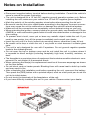
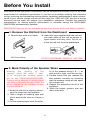
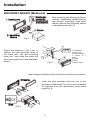
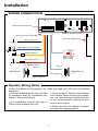
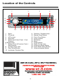
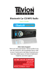
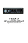
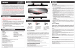
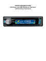
VRCD100M/RMCD100M CD Player and AM/FM Stereo Receiver with Auxilary Input jack Welcome! Dear Customer, CONGRATULATIONS. The VRCD100M/RMCD100M Compact Disc Player and AM/FM Stereo Receiver with AUX Input Jack, when used as described, will give you years of dependable service in your car, truck, RV, or mini-van. We have taken numerous measures in quality control to ensure that your product arrives in top condition and will perform to your satisfaction. In the rare event that your VRCD100M/RMCD100M Compact Disc Player and AM/FM Stereo Receiver with AUX Input Jack contains a damaged or missing item, does not perform as specified, requires warranty service, or you have an installation problem, DO NOT RETURN THIS PRODUCT TO THE STORE. PLEASE CALL OUR TOLL FREE NUMBER FROM THE U.S.A. AND CANADA 1-800-445-1797 and ask to speak with a member of our technical service team; or submit your questions by e-mail to [email protected] and a member of our technical service team will respond by e-mail to your questions. Our in-house technical service team will expedite delivery of your part, advise you on installation, or help troubleshoot a problem with you. If your product needs warranty service, our technical service team representative will help you obtain the fastest remedy possible under the warranty. Contents Precautions...................................................................................................... 2 Notes on Installation........................................................................................ 3 Before You Install............................................................................................. 4 Installation (DIN Front Mount).......................................................................... 5 Installation (Vehicle’s Brackets)....................................................................... 6 Wiring Connections.......................................................................................... 7 Location of Controls........................................................................................ 8 Basic Operation............................................................................................... 9 Radio Operation..............................................................................................10 CD Operation..................................................................................................10 AUX IN, RCA, & Subwoofer Control...............................................................11 Maintenance....................................................................................................11 Simple Troubleshooting Guide.......................................................................12 Specifications..................................................................................................12 Warranty..........................................................................................................13 Precautions This unit will only play the following discs. Type of disc Label on the disc CD • Do not attempt to modify the unit. Recorded material Size of disc Audio only 12 cm • Do not operate in extremely high or low temperatures. The temperature inside the vehicle should be between 32º F (0º C) and 100º F (37º C) before turning on your unit. • Modifying the unit will void the warranty. • Stop the vehicle before carrying out any operation that could interfere with your driving. Care of Discs • Handle the disc by its edge to keep the disc clean. Do not touch the disc’s surface. • Do not use CDs with labels or stickers attached. The label may leave a sticky residue when it begins to peel. • Do not use a CD with paste or ink residue on it. • Clean the discs with an optional cleaning cloth. Wipe each disc from the center out. 2 Notes on Installation • Disconnect negative battery terminal before starting installation. Consult the vehicle’s owner’s manual for proper instruction. • The unit is designed for a 12 Volt DC negative ground operation system only. Before installing the unit, make sure your vehicle is a 12 Volt DC negative ground system. • Mark the polarity of the existing speaker wires before disconnecting the old unit. • Be sure to connect the color coded leads according to the diagram. Incorrect connections may cause the unit to malfunction or damage the vehicle's electrical system. • Make sure all the connections are completely correct before turning on your unit. • When extending the ignition, memory backup or ground cable, use diameter of 0.75mm (AWG18) or more automotive grade cable to avoid wire deterioration or damage to the wire coating. • To prevent short circuit, never put or leave any metallic object inside the unit. If you smell or see smoke, turn off the power immediately and consult your dealer. • Insert the unit until it is firmly locked into mounting sleeve, otherwise it may fall out. • Be careful not to drop or shock the unit, it may break or crack because it contains glass parts. • The unit is only designed for use with 2 speakers. Do not ground negative speaker leads to the chassis ground. • Do not open the top or bottom cover and do not install the unit in a place where it is exposed to direct sunlight (including faceplate), high heat, humidity, moisture, or dust. • The faceplate is a precision piece of equipment that contains sensitive electronic components. Do not subject it to excessive shock. • When replacing the fuse(s), the replacement must be of the same amperage as shown on the fuse holder. • Do not block vents or heater panels. Blocking them will cause heat to build up inside and may result in fire. • After completing the installation and before operating the unit, reconnect the battery. Then press the (RES) button with a pointed object, such as a ball-point pen to set the unit to its initial status. • Do not touch the terminals of the faceplate or of the unit. • If you have difficulty installing this unit in your vehicle. Please contact your dealer. 3 Before You Install Automotive audio equipment installations can be troublesome at times, even to the most experienced of installation technicians. If you are not confident working with electrical wiring, removing and reinstalling interior panels, carpeting, dashboards or other components of your vehicle, please call our toll-free help line 1-800-445-1797 and our in-house technical service team will answer your installation questions. Contact the vehicle's manufacturer for vehicle specific instructions, or consider having the VRCD100M/ RMCD100M professionally installed. IMPORTANT: Remove the two transport screws from the top of the unit before installing. 1. Remove the Old Unit from the Dashboard A. Remove the outer trim frame. DIN Front Mount B. Insert the keys supplied with the old unit into both sides of the unit as shown in figure below until they click. Pull to remove the old unit from the dashboard. DO NOT DISCONNECT WIRES AT THIS TIME! 2. Mark Polarity of the Speaker Wires Marking the polarity of the speaker wires will make it easier to connect the existing speakers to the VRCD100M/RMCD100M. Consult wiring diagram of existing head unit before disconnecting any wires. If a wiring diagram is not available contact the manufacturer. ity of the speaker wires (+ & - ), as well as left or right, and front or rear. 4. Double check that you marked the first speaker correctly by checking that the speaker wires are the same at the head unit. 5. Repeat this procedure for all of the speakers. 6. Mark the power, ground, and any other wires also. 1. While the old unit is playing, disconnect the wires from one speaker. 2. Take a length of masking tape and fold it around the wire so it forms a flag. 3. On the masking tape mark the polar- 4 Installation DIN FRONT-MOUNT (Method A) After inserting the Mounting Sleeve into the dashboard, select tabs on top, bottom, and sides, then bend them to secure the mounting sleeve in the dash board.(Fig. 1) Fig. 1 Follow the diagram in Fig. 2 for installing the rear mounting strap to the head unit. The rear mounting strap will help keep the head unit from moving around inside the dashboard. Fig. 2 1. Dashboard 2. Nut (5mm) 3. Spring washer 4. Screw (5 x 25mm) 5. Screw 6. Strap 7. Plain washer Insert fingers into the groove in the front of frame to remove it. Insert the keys supplied with the unit in the grooves on both sides. The unit can be installed or removed from the dashboard using these keys.(Fig. 3) Fig. 3 5 Installation DIN REAR-MOUNT (Method B) Installation using the screw holes on both sides of the unit. 1. Screw holes on the side of the unit. 2. Screws. Use either truss screws (5 x 8mm) or flush surface screws (4 x 8mm), depending on the shape of the screw holes in the bracket. 3. Vehicle’s Factory Mounting Bracket 4. Dashboard or Console 5 Hook (Remove this part) Note: The mounting sleeve, outer trim ring, and the mounting strap are not used for this method of installation. PARTS 2 Keys 1 Hex Nut 2 Lock Washers 1 Sheet Metal Screw 1 Metal Support Strap 2 Flat Washers 1 Mounting Bolt 6 Installation WIRING CONNECTIONS Wiring Harness Socket Antenna Receptacle Wiring Harness & Plug Antenna Cable & Plug Black: Ground Blue/White: Auto-Antenna 5A 1A Yellow: Battery RCA Line Out Red = Right White = Left Red: ACC Power Front Speaker Out (L) Grey (+) White (+) Left Front Right Front Grey / Black (-) White / Black (-) Speaker Wiring Notes Follow the above wiring diagram to install the head unit with new or existing speakers. • This unit is designed for use with two • Never bridge or combine the speaker (2) speakers with an impedance be- wire outputs. When not using four speaktween 4 Ohms to 8 Ohms. ers, use electrical tape to tape the ends of the unused speaker outputs to pre• An impedance load of less than 4 vent a short circuit. Ohms could damage the unit. • Never ground the negative speaker terminals to chassis ground. 7 Location of the Controls 2 1 21 VOL+ 20 SEL 19 3 CD PLAYER / AM/FM STEREO RECEIVER 4 VRCD100M / RMCD100M 5 6 7 VOL- 18 17 16 15 14 1. 2. 3. 4. 5. Reset CD portal LCD screen Disc eject Station Up & Next Track / Fast Forward 6.Band button 7. Station Down & Previous Track / Fast Reverse 8. Auxiliary Input Jack 9. Play/ Pause Button 10. Loudness / Random Play 13 12 11 10 9 8 11. Distance / Repeat button 12. Stereo/ Scan Button 13. Clock Tune Button 14. Line-in button 15. EQ Button 16. Mute 17. Power Button 18. Radio Tuning knob 19. Volume increase Button 20. Audio Mode select Button 21. Volume decease Button 8 Basic Operation 1. Turning the Unit On / Off Press the power button to turn the unit on, press the POWER button again to turn the unit off. 4. Balance Press SEL Button until the display shows “BAL”, then use the VOL +/- Buttons to adjust the volume balance between the left & right speakers. 2. Mode Selection Press the BAND Button to select Radio Mode. Press the Play / Pause Button to when there is a CD in the unit to start playing the CD. Press the AUX Button when there is an audio source plugged into the Auxiliary Input Jack. 5. Loudness Control Press the LUD/RDM Button to emphasize the Bass output, the word “LOUD” on the display indicates that the loudness function is on. Press again to cancel. 6. Mute Press the MUTE Button to turn the volume off. Press this button again to turn the volume on again. Sound Characteristics 7. Preset Equalizer Function Press the EQ Button to choose the EQ mode between POP, CLASSIC, and ROCK. POP, CLS, or ROC will show on the display indicating which equalizer setting is in use. Use the SEL Button to access the units sound characteristics. Each time you press the SEL Button the unit advances to the next adjustable sound characteristic. VOL BAS TRE BAL 8. Clock The clock can be set anytime when the power is on. Press and hold the CLK button, the time will blink on the display. 1. Press the |<< Button to adjust the hour. 2. Press the >>| Button to adjust the minute. 3. Press the CLK Button again or leave the unit idle for new setting to effect. Press the CLK Button anytime to view the time clock display. 1. Volume Press the SEL Button until the display shows “VOL”. Use the VOL + / - Buttons to adjust the Volume level. The Volume levels are 0 - 63, the larger the VOL number, the higher the Volume level. 2. Bass Press the SEL Button until the display shows “BAS”. Use the VOL + / - Buttons to adjust the Bass level. When DSP is ON, bass control is not available. 3. Treble Press SEL Button until and the display shows “TRE”. Use the VOL + / - Buttons to adjust the Treble level. When DSP is ON, Treble control is not available. 9 Radio Operation 1. Choose A Radio Band Press the BAND Button anytime to access the radio function. The unit has one FM Band and one AM Band. Each press of the Band Button will change the radio from one Band to the other. 4. Intro Press the MO / INT Button to play the first 10 seconds of each track. Press this button again to when you find the track you wish to play. 5. Repeat Press the LOC / RPT Button to repeat the same track continuously. “RPT” will appear on the display. Press this button again to stop repeating. 2. Radio Tuning In Radio Mode, turn the Radio Tuning Knob to adjust the radio frequency. Press and hold the button, and the radio will go through the stations until you release the button. 6. Random Press and hold the LUD / RDM Button to play all the tracks in random order. “RDM” will appear on the display. Press and hold this button again to stop random play. 3. Mono / Stereo Press the MO / INT button to change the radio’s output from Mono to Stereo. This function only works in Radio Mode. Auxiliary Input CD Operation The Auxiliary Input Jack is on the right side of the unit. Insert a 3.5mm stereo cable into the Auxiliary Input Jack. Route the other end of the stereo cable to the headphone jack of any portable audio device such as a MP3 Player or DVD Player. Press the AUX button to choose the Auxilary Input Jack. Connect any portable audio device such as a DVD player or VCD player to the AUX IN cable. Use the volume control to adjust volume. 1. Insert/Eject CD Insert a disc into CD slot with label side up. The disc will be automatically loaded into the unit, even when it is off or at radio mode. The word “LOAD” will blink on the display and the CD will play automatically. Press the EJECT Button to eject the disc from the slot. When the disc is ejected, the unit will automatically switch to radio mode. 2. Selecting Tracks On the Head Unit, press the >>| Button to advance CD to the next track. Track numbers will be shown on the display. Press the |<< Button to go to a previous track. Track numbers will be shown on the display. RCA Output The RCA Line Out is on the back of the unit. (Refer to Wiring Diagram) This output is for connecting amplifier, equalizer, or other audio componement that requires a pre-amp out connection. (Red = Right, White = Left) Follow the manufacturers instructions for the audio component that you are connecting. 3. Play/ Pause CD Press the Button to pause the CD. Press this button again to resume playback. 10 Simple Troubleshooting Guide PROBLEM CAUSE/SOLUTION No Power Check wiring connections. Check and make sure the fuse is not blown. Replace with the proper rating/size fuse. Some errors occur in the LCD or nothing functions when buttons are pressed. Press the RESET Button. Unable to receive stations Check and make sure the antenna is connected properly. Poor radio reception Check and make sure the antenna is the correct length. Make sure the antenna is not broken. If the antenna is broken, replace it. The antenna is poorly grounded. Check and make sure the antenna is grounded at mounting location. CD’s cannot be loaded A CD is already loaded in the player. Eject CD. Songs keep skipping The CD is dirty or damaged. File information shows in LCD but will not play. Your file may be corrupt. MAINTENANCE If the fuse is bad, check the power connection and replace the fuse with a new one. If the same problem occurs, this might indicate a malfunction within the unit. Cleaning the Unit Do not use any liquids to clean this unit. Do not use petroleum distillates to clean this unit. Use a clean, dry cloth to clean this unit. Warning When replacing a fuse, do not use a fuse with a higher amperage rating than the fuse originally supplied to your unit, otherwise damage will result to your unit. Replacing the Fuse Make sure the amperage matches the specified value when replacing the fuse(s). 11 Specifications GENERAL Operating Power................................................................ 12 Volts DC, Negative Ground Output Wiring........................................................ Designed for using two speakers only RCA line out............................................................................ low-level outputs - 250 MV Output Impedance....................................................... Compatible 4 to 8 Ohm Speakers Fuses.............................................................................. 1 amp (Red) and 5 amp (Yellow) Dimensions............................................................... 178mm(W) x 150mm(D) x 50mm (H) Weight................................................................................................................. 3.163 Lb. CD PLAYER Signal / Noise Ratio................................................................................................ >50 dB Frequency Response................................................ 20-100 Hz < 5dB 10K-20KHz < 5dB Channel Separation................................................................................................. >50dB D / A Converter........................................................................................................... 1 Bit FM TUNER Tuning Range.......................................................................................... 87.1 - 108.6 MHz FM Sensitivity............................................................................................................. 10uV AM TUNER Tuning Range.......................................... . ................................................... 521 - 1739 KHz 12 Limited Warranty VIRTUAL REALITY SOUND LABS® products are designed and manufactured to provide a high level of troublefree performance. VIRTUAL REALITY SOUND LABS® warrants, to the original purchaser, that its products are free from defects in material and workmanship for 30 days from the date of original purchase. As part of our commitment to product excellence. VIRTUAL REALITY SOUND LABS® and/or it’s affiliates routinely improve the designs, materials or production methods of its existing products. Because it is impractical to publicize all changes in every product, we reserve the right to make such changes without notice. CONDITIONS OF WARRANTY: If during the 30 day warranty period your new product is found to be defective, VIRTUAL REALITY SOUND LABS® will repair such defect, or replace the product, without charge for parts or labor subject to the following conditions: 1. All repairs must be performed by VIRTUAL REALITY SOUND LABS® and/or its affiliates in Eatontown, New Jersey. 2. The equipment must not have been altered or been damaged through negligence, accident, or improper operation. 3. The replacement of parts are exempted from this warranty when replacement is necessary due to normal wear and tear. 4. All warranty claims must be accompanied by a copy of the sales receipt or bill of sale. 5. Repair or replacement parts supplied by VIRTUAL REALITY SOUND LABS® under this warranty are protected only for the unexpired portion of the original warranty. 6. In the case of car stereos, this warranty does not extend to the elimination of car static or motor noise; correction of antenna problems; costs incurred for the removal or reinstallation of the product; damage to tapes, speakers, accessories or car electrical systems. 7. VIRTUAL REALITY SOUND LABS® will not be responsible for any charge incurred for installation. OWNER’S RESPONSIBILITIES: VIRTUAL REALITY SOUND LABS® will make every effort to provide warranty service within a reasonable period of time. SHOULD YOU HAVE ANY QUESTIONS ABOUT SERVICE RECEIVED, OR IF YOU WOULD LIKE ASSISTANCE IN OBTAINING SERVICE, PLEASE CALL TOLL FREE 1-800-445-1797, 8:30am - 4:30pm EST. In order to provide you with the proper warranty service, we request that you adhere to the following procedure: 1. Include a copy of your sales receipt or bill of sale with your unit when it is returned for warranty service. 2. If it is necessary to return your product for service, please return it securely packed, preferably in the original shipping carton, and freight and insurance prepaid to the following address: VIRTUAL REALITY SOUND LABS, Service Department, 41 James Way, Eatontown, New Jersey 07724. 3. Please include a detailed explanation of the problem you are having. 4. If your product is found by VIRTUAL REALITY SOUND LABS® to have a defect in material or workmanship, within the warranty period, it will be repaired or replaced at no charge and returned to you prepaid. Where permitted by Iaw VIRTUAL REALITY SOUND LABS® liability shall be limited to that set forth in this warranty. This warranty shall be the exclusive remedy of the purchaser. VIRTUAL REALITY SOUND LABS® makes no other warranty of any kind, expressed or implied; and all implied warranties, are hereby disclaimed by VIRTUAL REALITY SOUND LABS® and excluded from this warranty. VIRTUAL REALITY SOUND LABS® and/or its affiliates, the manufacturer, distributor and seller shall not be liable for any injury, loss or damage, incidental or consequential, arising out of the use or intended use of the product. ©2007 Virtual Reality Sound Labs® All designs, logos and images are the exclusive property of Virtual Reality Sound Labs® and/or its affiliates. All rights reserved. 011507 Printed in China 00000