1
Model RN-MF1
Machine Codes: M016/M017
Field Service Manual
30 November, 2009
Safety Notices
Important Safety Notices
Prevention of Physical Injury
1. Before disassembling or assembling parts of the machine and peripherals, make sure that the machine
power cord is unplugged.
2. The wall outlet should be near the machine and easily accessible.
3. If any adjustment or operation check has to be made with exterior covers off or open while the main
switch is turned on, keep hands away from electrified or mechanically driven components.
4. The machine drives some of its components when it completes the warm-up period. Be careful to keep
hands away from the mechanical and electrical components as the machine starts operation.
5. The inside and the metal parts of the fusing unit become extremely hot while the machine is operating.
Be careful to avoid touching those components with your bare hands.
Health Safety Conditions
Toner is non-toxic, but if you get either of them in your eyes by accident, it may cause temporary eye
discomfort. Try to remove with eye drops or flush with water as first aid. If unsuccessful, get medical attention.
Observance of Electrical Safety Standards
The machine and its peripherals must be serviced by a customer service representative who has completed
the training course on those models.
Safety and Ecological Notes for Disposal
1. Do not incinerate toner bottles or used toner. Toner dust may ignite suddenly when exposed to an
open flame.
2. Dispose of used toner, the maintenance unit which includes developer or the organic photoconductor
in accordance with local regulations. (These are non-toxic supplies.)
3. Dispose of replaced parts in accordance with local regulations.
• To prevent a fire or explosion, keep the machine away from flammable liquids, gases, and aerosols.
A fire or an explosion might occur.
1
• The Controller board on the MF model contains a lithium battery. The danger of explosion exists if a
battery of this type is incorrectly replaced. Replace only with the same or an equivalent type
recommended by the manufacturer. Discard batteries in accordance with the manufacturer's
instructions and local regulations
Laser Safety
The Center for Devices and Radiological Health (CDRH) prohibits the repair of laser-based optical units
in the field. The optical housing unit can only be repaired in a factory or at a location with the requisite
equipment. The laser subsystem is replaceable in the field by a qualified Customer Engineer. The laser
chassis is not repairable in the field. Customer engineers are therefore directed to return all chassis and
laser subsystems to the factory or service depot when replacement of the optical subsystem is required.
• Use of controls, or adjustment, or performance of procedures other than those specified in this manual
may result in hazardous radiation exposure.
WARNING
WARNING:
Turn off the main switch before attempting any of the procedures in the Laser Optics Housing Unit section.
Laser beams can seriously damage your eyes.
CAUTION MARKING:
2
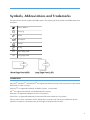
Symbols, Abbreviations and Trademarks
This manual uses several symbols and abbreviations. The meaning of those symbols and abbreviations are
as follows:
See or Refer to
Clip ring
Screw
Connector
Clamp
E-ring
SEF
Short Edge Feed
LEF
Long Edge Feed
Trademarks
Microsoft®, Windows®, and MS-DOS® are registered trademarks of Microsoft Corporation in the United
States and /or other countries.
PostScript® is a registered trademark of Adobe Systems, Incorporated.
PCL® is a registered trademark of Hewlett-Packard Company.
Ethernet® is a registered trademark of Xerox Corporation.
PowerPC® is a registered trademark of International Business Machines Corporation.
Other product names used herein are for identification purposes only and may be trademarks of their
respective companies. We disclaim any and all rights involved with those marks.
3
TABLE OF CONTENTS
Safety Notices.....................................................................................................................................................1
Important Safety Notices...............................................................................................................................1
Laser Safety.....................................................................................................................................................2
Symbols, Abbreviations and Trademarks.........................................................................................................3
Trademarks.....................................................................................................................................................3
1. Product Information
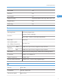
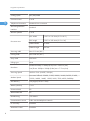
Specifications......................................................................................................................................................9
Machine Overview..........................................................................................................................................10
Component Layout.......................................................................................................................................10
Paper Path....................................................................................................................................................11
Drive Layout..................................................................................................................................................12
Machine Configuration....................................................................................................................................13
2. Installation
Installation Requirements.................................................................................................................................15
Environment..................................................................................................................................................15
Machine Level..............................................................................................................................................16
Machine Space Requirement.....................................................................................................................16
Power Requirements....................................................................................................................................16
Installation Procedure..................................................................................................................................17
3. Preventive Maintenance
PM Intervals......................................................................................................................................................19
PM Parts........................................................................................................................................................19
Yield Counter................................................................................................................................................19
4. Replacement and Adjustment
Before You Start...............................................................................................................................................21
Special Tools....................................................................................................................................................22
Exterior Covers.................................................................................................................................................23
Front Cover...................................................................................................................................................23
Left Cover......................................................................................................................................................24
Rear Cover...................................................................................................................................................27
Right Cover...................................................................................................................................................28
Top Cover.....................................................................................................................................................29
ADF....................................................................................................................................................................31
4
ADF Unit........................................................................................................................................................31
Original Tray................................................................................................................................................32
ADF Feed Unit..............................................................................................................................................32
ADF Separation Pad....................................................................................................................................33
ADF Front Cover .........................................................................................................................................33
ADF Rear Cover...........................................................................................................................................34
ADF Cover....................................................................................................................................................34
ADF Motor....................................................................................................................................................35
Original Set Sensor......................................................................................................................................36
ADF Cover Open Sensor............................................................................................................................37
ADF Feed Sensor.........................................................................................................................................38
ADF Drive Board..........................................................................................................................................39
Scanner Unit.....................................................................................................................................................40
Operation Panel...........................................................................................................................................40
Scanner Top Cover......................................................................................................................................41
Scanner Carriage Unit.................................................................................................................................42
Exposure Lamp.............................................................................................................................................44
Lamp Stabilizer Board.................................................................................................................................45
Scanner Motor.............................................................................................................................................46
Laser Unit..........................................................................................................................................................48
Caution Decal Locations.............................................................................................................................48
Laser Unit......................................................................................................................................................48
Polygon Mirror Motor.................................................................................................................................49
Paper Feed and Exit.........................................................................................................................................51
Paper Feed Roller........................................................................................................................................51
Friction Pad...................................................................................................................................................52
Paper End Sensor.........................................................................................................................................52
By-pass Feed Roller.....................................................................................................................................52
By-Pass Feed Roller Friction Pad.................................................................................................................54
By-pass Feed Sensor...................................................................................................................................55
Paper Feed Clutch.......................................................................................................................................55
Relay Clutch.................................................................................................................................................57
Registration Clutch.......................................................................................................................................57
5
Toner End Sensor.........................................................................................................................................57
Paper Exit Sensor.........................................................................................................................................58
Relay Sensor.................................................................................................................................................58
Inverter Sensor.............................................................................................................................................59
Registration Roller and Sensor....................................................................................................................59
Paper Transfer..................................................................................................................................................63
Transfer Roller..............................................................................................................................................63
Fusing................................................................................................................................................................64
Fusing Unit....................................................................................................................................................64
Thermostat....................................................................................................................................................66
Thermistor.....................................................................................................................................................67
Fusing Lamp..................................................................................................................................................68
Hot Roller......................................................................................................................................................69
Pressure Roller..............................................................................................................................................70
Hot Roller Stripper Pawls.............................................................................................................................70
Motors...............................................................................................................................................................72
Main Motor..................................................................................................................................................72
Duplex Motor (For M017)..........................................................................................................................72
Electrical Components.....................................................................................................................................74
Layout of PC Boards....................................................................................................................................74
PSU................................................................................................................................................................78
Charge Terminal Case................................................................................................................................82
Others................................................................................................................................................................83
Cooling Fan..................................................................................................................................................83
Speaker........................................................................................................................................................83
Quenching Lamp..........................................................................................................................................84
Image Adjustment.............................................................................................................................................85
Registration Adjustment...............................................................................................................................85
5. System Maintenance Reference
Service Program Mode....................................................................................................................................87
Overview......................................................................................................................................................87
Maintenance Mode Menu..........................................................................................................................87
Fax Service Test Menu..............................................................................................................................104
6
Configuration and Maintenance Page .......................................................................................................106
Overview....................................................................................................................................................106
Firmware Updating........................................................................................................................................108
Checking the Machine Firmware Version...............................................................................................108
Updating the Controller Firmware...........................................................................................................108
Updating the Engine Firmware.................................................................................................................110
Updating the Boot Loader Firmware.......................................................................................................112
Updating Failure........................................................................................................................................112
FW Update Tool Messages......................................................................................................................112
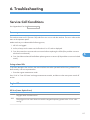
6. Troubleshooting
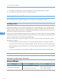
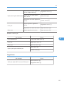
Service Call Conditions.................................................................................................................................117
Summary....................................................................................................................................................117
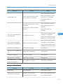
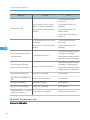
Engine SC...................................................................................................................................................117
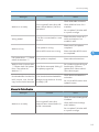
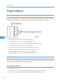
Image Problems.............................................................................................................................................124
Overview....................................................................................................................................................124
Test Page Printing......................................................................................................................................124
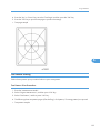
Test Pattern Printing....................................................................................................................................125
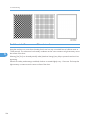
Dark lines in halftone areas at 75mm Intervals.......................................................................................126
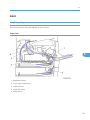
Jam..................................................................................................................................................................127
Jam Sensor Layout.....................................................................................................................................127
Jam Message List.......................................................................................................................................128
7. Energy Saving
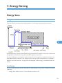
Energy Save...................................................................................................................................................131
Energy Saver Modes................................................................................................................................131
Paper Save.....................................................................................................................................................133
Effectiveness of Duplex/Combine Function............................................................................................133
7
8
1. Product Information
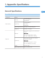
Specifications
1
See "Appendices" for the following information:
• "General Specifications"
• "Printer"
• "Copier"
• "Scanner"
• "Fax"
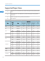
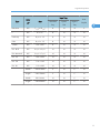
• "Supported Paper Sizes"
9
1. Product Information
Machine Overview
1
10
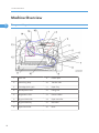
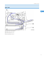
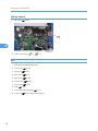
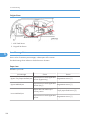
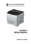
Component Layout
1.
Laser unit
9.
Friction pad
2.
Quenching lamp
10.
Transfer roller
3.
Cartridge (AIO-type)
11.
Paper Tray
4.
Development roller
12.
Fusing Unit
5.
Registration roller
13.
Pressure Roller
6.
By-pass feed roller
14.
Paper exit roller
7.
By-pass feed tray
15.
Hot Roller
8.
Paper feed roller
16.
Drum
Machine Overview
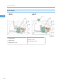
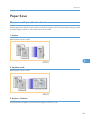
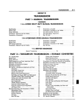
Paper Path
1
[A] Duplex section (For M017)
[B] Standard paper tray unit
[C] Optional paper tray unit
11
1. Product Information
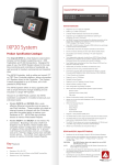
Drive Layout
1
1. Duplex Motor
2. Main Motor
3. Registration Clutch
12
4. Replay Clutch
5. Paper Feed Clutch
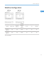
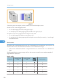
Machine Configuration
Machine Configuration
1
Optional
Tray
(M355)
PCL PS
Fax
USB Host
Models
Duplex Unit
Optional
Memory
RN-MF1a
(M016)
NA
NA
250x1
Yes
Yes
Yes
RN-MF1b
(M017)
Auto
NA
250x1
Yes
Yes
Yes
NA: Not Available
13
1. Product Information
1
14
2. Installation
Installation Requirements
Environment
2
1. Temperature Rage: 10°C to 32°C (50°F to 89.6°F)
2. Humidity Range: 15% to 80% RH
3. Ambient Illumination: Less than 2,000 lux (do not expose to direct sunlight)
4. Ventilation: 3 times/hr/person
5. Do not put the machine in areas with sudden temperature changes. This includes:
• Areas directly exposed to cool air from air conditioning
• Areas directly exposed to heat from a heating system.
6. Do not put the machine in areas exposed to corrosive gas.
7. Do not install the machine at locations over 2,000 m (6,562 ft.) above sea level.
8. Put the machine on a strong, level base. (Tilting towards any side must be no more than 3 mm.)
9. Do not put the machine in areas with strong vibrations.
15
2. Installation
Machine Level
Front to back: Within 5 mm (0.2") of level
Right to left: Within 5 mm (0.2") of level
2
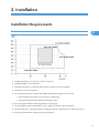
Machine Space Requirement
Put the machine near a power source with these clearances:
A: Over 10 cm (4")
B: Over 20 cm (7.9")
C: Over 20 cm (7.9")
D: Over 70 cm (27.6")
Power Requirements
• Make sure that the plug is tightly in the outlet.
• Avoid multi-wiring.
• Make sure that you ground the machine.
Input voltage level
16
NA: 120 V, TW: 110 V, 60 Hz: Less than 10 A
EU/ Asia/ CHN: 220 V to 240 V, 50 Hz/60 Hz: Less than 5 A
Installation Requirements
Permitted voltage fluctuation: 10%
Do not set anything on the power cord.
Installation Procedure
Refer to the "User Guide".
2
17
2. Installation
2
18
3. Preventive Maintenance
PM Intervals
PM Parts
There are no PM parts in this machine.
3
• Other than the three Yield Parts listed below, there are essentially no PM parts required for this product.
• These three items will need to be replaced in cases where their yield is near, however, given the ACV
(Average Copy Volume) for this product, these "yield parts*1 " are expected to outlast the working
life of the machine.
*1 "Yield Parts": Parts whose expected yield is longer than the machine lifetime when taking into
consideration the machine's ACV.
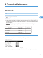
Description
Expected Yield
Q'ty/unit
Paper Feed Roller
120 K prints
1
Transfer Roller
120 K prints
1
Fusing Unit
120 K prints
1
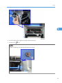
Yield Counter
Yield counters for each yield part can be checked by the following methods.
Configuration Page
These yield counters are printed under the supplies Info on the "Configuration Page" as shown above.
19
3. Preventive Maintenance
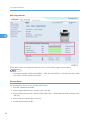
Web Image Monitor
3
These yield counters are displayed under the "Toner" on the "Status" page as shown above.
• The machine displays "Life End Feed Roller", "Life End Transfer Roller" or "Life End Fuser Unit" when
one of these counters reaches each yield.
Counter Reset
The process below shows how to reset the yield counters.
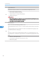
1. Enter the "Maintenance Mode".
2. Select "Engine Maintenance", and then press "OK" key.
3. Select "Reset Fusing Unit Life", "Reset Transfer Roller Life" or "Reset Paper Feed Life" and then press
"OK" key.
4. Select "Execute" and then press "OK" key.
5. Exit the "Maintenance Mode".
20
4. Replacement and Adjustment
Before You Start
• If there are printer jobs in the machine, print out all jobs in the printer buffer.
• Turn off the main power switch and unplug the machine before you do the procedures in this section.
4
21
4. Replacement and Adjustment
Special Tools
• PC: Windows 2000/XP/Vista, Windows Server 2003/2003 R2, 2008.
• USB or network cable
• A computer is necessary to update the firmware.
4
22
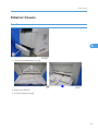
Exterior Covers
Exterior Covers
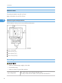
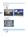
Front Cover
4
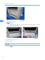
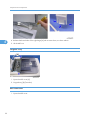
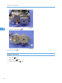
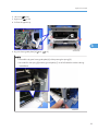
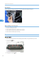
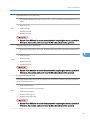
1. Pull out the standard paper tray [A].
2. Remove two tabs [A].
3. Pull out the bypass tray [B].
23
4. Replacement and Adjustment
4
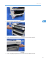
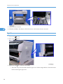
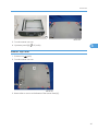
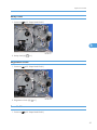
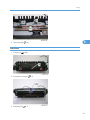
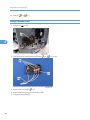
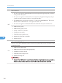
4. Open the front cover [A].
• To open the front cover, push the cover release button [B] and (carefully) pull the cover forward
and open (it hinges downward).
5. Push the right hinge [A] to release.
6. Front cover [B]
Left Cover
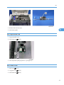
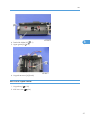
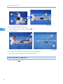
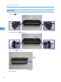
1. Front cover (
24
p.23)
Exterior Covers
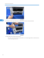
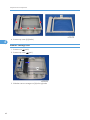
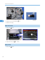
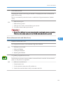
2. Remove two screws [A] on the left cover.
4
3. Pull the front upper part [A] of the left cover (as shown above) to release the hooks.
4. Pull the rear upper part [A] of the left cover (as shown above) to release the hooks.
25
4. Replacement and Adjustment
4
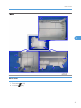
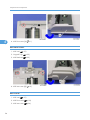
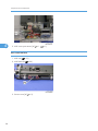
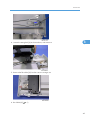
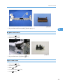
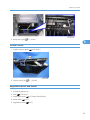
5. Pull the front bottom part of the left cover [A] (as shown above) to release the hooks.
6. Remove the Left cover [A] as shown above.
• There are many hooks and tabs inside the left cover. See the images below in the Note section
before removing the left cover.
26
Exterior Covers
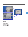
NOTE:
4
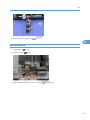
Rear Cover
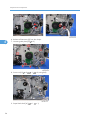
1. Front cover (
2. Left cover (
p.23)
p.24)
27
4. Replacement and Adjustment
4
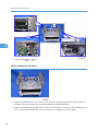
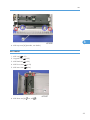
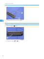
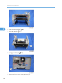
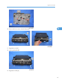
3. Open the rear cover [A]
4. Slide the shaft [B] in the direction of the blue arrow, and remove the rear cover [A].
Right Cover
1. Front cover (
p.23)
2. Rear cover (
p.27)
3. Right cover [A] ( x 3, hook at arrow mark)
• There are many hooks and tabs inside the right cover. See the images below in the Note section
before removing the right cover.
28
Exterior Covers
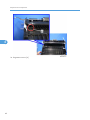
NOTE:
4
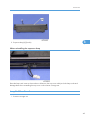
Top Cover
1. Front cover (
2. Left cover (
3. Rear cover (
4. Scanner unit (
p.23)
p.24)
p.27)
p.40)
29
4. Replacement and Adjustment
4
5. Top cover [A] (
x 3,
x 4)
When installing the top cover
• When re-installing the top cover, always verify that the two paperweights [A] are lifted. If they are
not lifted to fit into the paper slot, the paperweights [A] could be damaged.
• Make sure that these paperweights [A] can be moved smoothly (up and down) after installing the top
cover. If these paperweights do not move smoothly, try installing the top cover again.
30
ADF
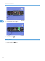
ADF
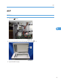
ADF Unit
1. Left cover (
p.24)
4
2. Disconnect the ADF harness [A] and ground-wire [B] ( x 1).
3. Open the ADF unit [A]
31
4. Replacement and Adjustment
4
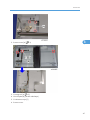
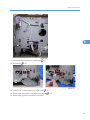
4. Release the three hooks of the right hinge [A] with a screw driver, as shown above.
5. Lift the ADF unit.
Original Tray
1. Open the ADF cover [A].
2. Original tray [B] (Two tabs)
ADF Feed Unit
1. Open the ADF cover.
32
ADF
2. Release the lock lever [A]
3. ADF feed unit [B]
4
ADF Separation Pad
1. Open the ADF cover.
2. ADF feed unit (
p.32)
3. ADF separation pad [A] (hook x 2, spring x 1)
ADF Front Cover
1. ADF unit (
p.31)
2. Original Tray (
p.32)
3. ADF feed unit (
p.32)
33
4. Replacement and Adjustment
4
4. ADF front cover [A] ( x 1)
ADF Rear Cover
1. ADF unit (
p.31)
2. Original Tray (
p.32)
3. ADF feed unit (
p.32)
4. ADF rear cover [A] ( x 2)
ADF Cover
1. ADF unit (
34
p.31)
2. ADF front cover (
p.33)
3. ADF rear cover (
p.34)
ADF
4
4. ADF top cover [A] (two tabs, two hooks)
ADF Motor
1. ADF unit (
p.31)
2. Original Tray (
p.32)
3. ADF feed unit (
p.32)
4. ADF front cover (
p.33)
5. ADF rear cover (
p.34)
6. ADF drive unit [A] ( x 4, all
s)
35
4. Replacement and Adjustment
4
7. ADF motor assembly [A] ( x 2)
8. ADF motor [A] ( x 2)
Original Set Sensor
1. ADF unit (
p.31)
2. ADF feed unit (
p.32)
3. ADF motor assembly (
36
p.35)
ADF
4. Feed roller holder [A] ( x 1)
5. Upper guide [B] ( x 2)
4
6. Original set sensor [A] (hooks)
ADF Cover Open Sensor
1. Original tray (
2. ADF rear cover (
p.32)
p.34)
37
4. Replacement and Adjustment
4
3. ADF cover open sensor [A] ( x 1,
ADF Feed Sensor
1. ADF unit (
p.31)
2. ADF feed unit (
p.32)
3. Sensor cover [A] ( x 2)
38
x 1)
ADF
4. ADF feed sensor [A] (hooks,
x 1)
4
ADF Drive Board
1. Original tray (
2. ADF rear cover (
p.32)
p.34)
3. ADF drive board [A] (no screws, all plugs (
)s and hooks)
39
4. Replacement and Adjustment
Scanner Unit
1. Front cover (
p.23)
2. Left cover (
p.24)
3. Rear cover (
p.27)
4
4. Slide the scanner unit [A] in the direction of the blue arrow, and remove it ( x 4, ground cable x 2,
flat cable x 1,
x 3, x 3).
5. ADF unit (
p.31)
6. Operation Panel (
p.40)
7. Scanner Unit [A]
Operation Panel
1. Scanner unit (
2. ADF unit (
40
p.40)
p.31)
Scanner Unit
3. Turn the scanner unit over.
4. Operation panel [A] ( x 3, hooks)
4
Scanner Top Cover
1. Scanner unit (
p.40)
2. Turn the scanner unit over.
3. Remove the six screws on the bottom of the scanner base [A].
41
4. Replacement and Adjustment
4
4. Scanner top cover [A] (hooks)
Scanner Carriage Unit
1. Scanner unit (
p.40)
2. Scanner top cover (
p.41)
3. Slide the scanner carriage unit [A] to the right side.
42
Scanner Unit
4. Loosen the timing belt [A] as shown above, and remove it.
4
5. Remove the flat cable [A] from the scanner carriage unit.
6. Bar holder [A] ( x 1)
43
4. Replacement and Adjustment
4
7. Carriage bar [A] and scanner carriage unit [B]
Exposure Lamp
1. Scanner carriage unit (
p.42)
2. Carriage top cover [A] ( x 2,
44
x 1)
Scanner Unit
3. Exposure lamp [A] (hooks)
4
When reinstalling the exposure lamp
Place the lamp cord wires as shown above. Otherwise, the top cover could pinch the lamp cords and
damage them when reinstalling the top cover on the scanner carriage unit.
Lamp Stabilizer Board
1. Scanner carriage unit
45
4. Replacement and Adjustment
4
2. Carriage bottom cover [A] ( x 2)
3. Lamp stabilizer [A] (
x 1)
Scanner Motor
1. Scanner carriage unit (
46
p.42)
Scanner Unit
2. Scanner motor [A] ( x 3)
4
3. Carriage rail [A] ( x 2)
4. Ground plate [B] (double-sided tape)
5. Conductance tape [C]
6. Scanner motor
47
4. Replacement and Adjustment
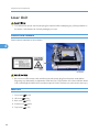
Laser Unit
• Turn off the main power switch and unplug the machine before attempting any of the procedures in
this section. Laser beams can seriously damage your eyes.
Caution Decal Locations
Caution decal is attached as shown below.
4
• Be sure to turn off the main switch and disconnect the power plug from the power outlet before
beginning any disassembly or adjustment of the laser unit. This machine uses a class IIIB laser beam
with a wavelength of 648 to 663 nm and an output of 9 mW. The laser can cause serious eye injury.
Laser Unit
1. Front cover (
2. Left cover (
3. Rear cover (
4. Scanner unit (
5. Top cover (
48
p.23)
p.24)
p.27)
p.40)
p.29)
Laser Unit
6. Laser unit [A] ( x 3, ground screw x 3,
x 2)
4
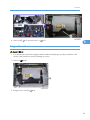
Polygon Mirror Motor
• Turn off the main switch and unplug the machine before attempting any of the procedures in this
section. Laser beams can seriously damage your eyes.
1. Laser unit (
p.48)
2. Polygon mirror cover [A] ( x 2)
49
4. Replacement and Adjustment
4
3. Polygon mirror motor [A] ( x 4,
x 1)
• Never touch the surface of the mirror with bare hands.
50
Paper Feed and Exit
Paper Feed and Exit
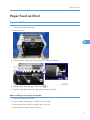
Paper Feed Roller
1. Pull out the standard paper tray.
2. Remove the AIO.
4
3. Set the machine with the rear side facing down, resting on the table.
4. Slide the paper feed shaft [A] to the left side (
x 2).
5. Slide the paper feed roller [B] to right side, and remove it (hook).
After installing a new paper feed roller
1. Enter the "Maintenance Mode".
2. Select "Engine Maintenance", and then press "OK" key.
3. Select "Reset Paper Feed Life" and then press "OK" key.
4. Select "Execute" and then press "OK" key.
51
4. Replacement and Adjustment
Friction Pad
4
1. Remove the paper tray unit from the machine before removing the friction pad.
2. Friction pad [A] (2 hooks, 1 spring)
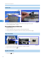
When reinstalling the friction pad follow this order:
1. Replace the spring.
2. Insert the right side of the friction pad first, followed by the left side.
3. Gently push the friction pad down into the slot and then pull forward very slightly.
Paper End Sensor
1. Set the machine with the rear side facing down, resting on the table.
2. Paper end sensor [A] (hooks,
By-pass Feed Roller
1. Front cover (
52
p.23)
x 1)
Paper Feed and Exit
2. Left cover (
3. Right cover (
p.24)
p.28)
4. Pull out the paper tray.
4
5. By-pass lower guide plate [A] ( x 4,
x 2)
NOTE:
• Reinstall the by-pass lower guide plate [A] while pressing the spring [B].
• Be careful for the spring [B] and the ground plate [C] not to fall inside the machine during
reinstallation.
53
4. Replacement and Adjustment
6. By-pass upper guide plate [A] (hooks)
4
7. By-pass solenoid cover, by-pass solenoid [B] ( x 1)
8. Gear [C] (hook)
9. Slide the by-pass feed roller shaft [A] to the left side, and remove it.
10. Remove the metal cover [B] from the by-pass feed roller [C].
By-Pass Feed Roller Friction Pad
1. By-pass feed roller (
54
p.52)
Paper Feed and Exit
2. By-pass feed roller friction pad [A] (hooks, spring x 1)
4
By-pass Feed Sensor
1. Front cover (
p.23)
2. Right cover (
p.28)
3. By-pass feed sensor [A] (hooks,
x 1)
Paper Feed Clutch
1. Top cover (
p.29)
2. Scanner unit (
3. ECB (
p.40)
p.74)
4. Controller board (
5. FCU (
p.76)
p.77)
55
4. Replacement and Adjustment
4
6. Release all harnesses [A] from the clamps.
7. Harness guide plate [B] ( x 2)
8. Drive unit [A] ( x 5,
9. Paper feed clutch [A] (
56
x 1,
x 1,
x 2, timing belt)
x 1)
Paper Feed and Exit
Relay Clutch
1. Drive unit (
p.55 "Paper Feed Clutch")
4
2. Relay clutch [A] (
x 1)
Registration Clutch
1. Drive unit (
p.55 "Paper Feed Clutch")
2. Registration clutch [A] (
x 1)
Toner End Sensor
1. Drive unit (
p.55 "Paper Feed Clutch")
57
4. Replacement and Adjustment
4
2. Reflective sensor with bracket [A] ( x 1)
3. Reflective sensor [B]
Paper Exit Sensor
1. Rear cover (
p.27)
2. Paper exit sensor [A] (
Relay Sensor
1. Rear cover (
58
p.27)
x 1, hooks)
Paper Feed and Exit
2. Relay sensor [A] (
x 1, hooks)
Inverter Sensor
1. Duplex transport guide (
2. Inverter sensor [A] (
4
p.78 "PSU")
x 1, hooks)
Registration Roller and Sensor
1. Pull out the paper tray.
2. PSU (
p.78 "PSU")
3. Paper feed clutch (
4. Relay clutch (
p.55 "Paper Feed Clutch")
p.57)
5. Registration clutch (
p.57)
59
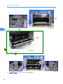
4. Replacement and Adjustment
4
6. Heat insulating plate [A] ( x 2)
7. Exit roller base [B] ( x 2)
8. Imaging unit base [A] ( x 4)
9. Remove the four screws in the right frame [A].
60
Paper Feed and Exit
10. Remove the four screws in the left frame [A].
4
11. Registration unit [A]
12. Upper guide plate [B]
13. Registration roller [A]
61
4. Replacement and Adjustment
4
14. Registration sensor [A]
62
Paper Transfer
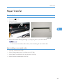
Paper Transfer
Transfer Roller
1. Front cover (
p.23)
2. Remove the AIO.
4
3. Remove the transfer roller [A] (Bushing x 1, spring x 2, gear x 1) as shown above.
• Do not touch the transfer roller surface, when reinstalling the new transfer roller.
After installing a new transfer roller
1. Enter the "Maintenance Mode".
2. Select "Engine Maintenance", and then press "OK" key.
3. Select "Reset Transfer Roller Life" and then press "OK" key.
4. Select "Execute" and then press "OK" key.
63
4. Replacement and Adjustment
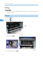
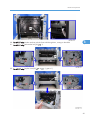
Fusing
• Switch off the main power, unplug the machine from its power source, and allow the fusing unit to
cool before removing it.
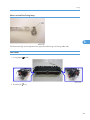
Fusing Unit
1. Front cover (
4
2. Left cover (
3. Rear cover (
p.23)
p.24)
p.27)
4. Entrance guide [A] (
x 1)
5. Disconnect the three harnesses (
64
x 2)
Fusing
4
6. Pass the cable [A] through the hole [B] inside the machine.
7. Fusing unit [C] ( x 4)
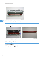
NOTE:
Make sure that the two bushings [A] remain be setting.
65
4. Replacement and Adjustment
Reinstallation
Pass the cable [A] of fusing unit through the hole [B] outside, after setting the fusing unit.
4
After installing a new fusing unit
1. Enter the "Maintenance Mode".
2. Select "Engine Maintenance", and then press "OK" key.
3. Select "Reset Fusing Unit Life" and then press "OK" key.
4. Select "Execute" and then press "OK" key.
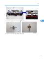
Thermostat
• Do not recycle a thermoswitch that is already opened. Safety is not guaranteed if you do this.
1. Fusing unit [A] (
x 3)
2. Fusing upper cover [A] ( x 4)
66
Fusing
3. Thermostat [A] ( x 2)
4
Thermistor
1. Fusing unit (
p.64)
2. Fusing front cover [A] ( x 2)
3. Thermistor [A] ( x 1)
67
4. Replacement and Adjustment
Fusing Lamp
1. Fusing Unit (
p.64)
4
2. Fusing side covers [A] ( x 2 each)
3. Ground-wires ( x 1 each)
4. Fusing lamp [A]
68
Fusing
When reinstall the fusing lamp
4
The flat terminal [A] must be placed on the right side of the fusing unit (fusing cable side).
Hot Roller
1. Fusing lamp (
p.68)
2. Brackets [A] ( x 2)
69
4. Replacement and Adjustment
4
3. Hot roller [A] (C-ring x 2, gear x 1, bushing x 2)
Pressure Roller
1. Hot roller (
p.69)
2. Pressure roller [A] (Bearing x 2)
Hot Roller Stripper Pawls
1. Fusing unit (
p.64)
2. Fusing unit upper cover (
70
p.66)
Fusing
3. Metal holders [A] (1 holder for each pawl:
x 2 each)
4
4. Hot roller stripper pawls [A] (1 spring for each pawl)
71
4. Replacement and Adjustment
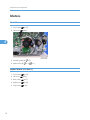
Motors
Main Motor
1. Front cover (
2. Left cover (
p.23)
p.24)
4
3. Harness guide [A] ( x 2)
4. Main motor [B] ( x 4,
x 1)
Duplex Motor (For M017)
1. Front cover (
2. Left cover (
p.24)
3. Rear cover (
p.27)
4. Right cover (
p.28)
5. Top cover (
72
p.23)
p.29)
Motors
6. Duplex motor [A] ( x 2,
x 1)
4
73
4. Replacement and Adjustment
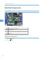
Electrical Components
Layout of PC Boards
4
[A]
ECB (Engine Controller Board)
[B]
Controller Board
[C]
FCU (Fax Control Unit) - behind the main controller board
[D]
USB Board
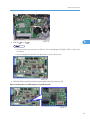
ECB (Engine Controller Board)
1. Front cover (
2. Left cover (
74
p.23)
p.24)
Electrical Components
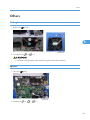
3. ECB [A] ( x 4, all
s)
4
• Do not connect any connectors to CN181 when reinstalling the ECB [A]. CN181 is only used
for factory.
• Do not change the dip switch. The dip switch is only for factory use.
4. EEPROM (Electronically Erasable Programmable Read Only Memory) [A]
When installing the new ECB (Engine Controller Board)
75
4. Replacement and Adjustment
1. Remove the EEPROM from the old ECB.
2. Install it on the new ECB after replacing the ECB.
3. Replace the EEPROM if the EEPROM on the old ECB is defective.
• Keep the EEPROM away from any objects that can cause static electricity. Static electricity can
damage EEPROM data.
• Make sure that the EEPROM is correctly installed on the ECB.
EEPROM
4
• Replacement procedures for the new EEPROM are included in the "ECB (Engine Controller Board)"
replacement procedure. Refer to "ECB (Engine Controller Board)" for details.
• Do the following settings after installing a "new" EEPROM.
-Input the PnP Name, Destination in Maintenance mode.
-Adjust registration in Maintenance mode.
-Input serial number on the serial number input display after installing the new EEPROM
• Ask your supervisor about how to access the serial number input display.
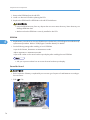
Controller Board
• Risk of explosion if battery is replaced by an incorrect type. Dispose of used batteries according to
the instructions.
1. ECB (
76
p.74)
Electrical Components
2. Controller board [A] ( x 4, flat cable x 1, all
s)
FCU
1. ECB (
p.74)
2. Controller board(
p.76)
4
3. Controller board bracket [A] ( x 3)
4. FCU [A] ( x 4)
77
4. Replacement and Adjustment
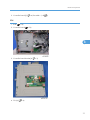
USB Host Board
1. Left cover (
p.24)
4
2. USB host board [A] ( x 2,
x 1)
PSU
1. Pull out the standard paper tray.
2. Front cover (
3. Left cover (
p.23)
p.24)
4. Rear cover (
p.27)
5. Right cover (
p.28)
6. Scanner unit (
p.40)
7. Top cover (
8. ECB (
p.29)
p.74)
9. Controller board bracket (
10. Drive unit (
78
p.77)
p.55 "Paper Feed Clutch")
Electrical Components
4
11. Disconnect three connectors in left frame(
x 1)
12. Bracket [A] ( x 2)
13. Main power switch bracket [A] in right frame( x 2)
14. Remove the main power cord [B] as sown above(
x 2).
15. Remove the ground wire and two connectors.
79
4. Replacement and Adjustment
4
16. Rear low cover [A] ( x 3)
17. Entrance guide [A]
18. Fusing Unit(
p.64)
19. For M017 only: Duplex transport guide [A] ( x 2)
80
Electrical Components
20. For M017 only: Set the machine with the front side facing down, resting on the table.
21. For M017 only: Release the link [A] (
x 1)
22. For M017 only: Duplex cover [A] ( x 4,
4
x 1, gear x 1)
81
4. Replacement and Adjustment
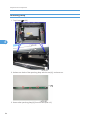
23. PSU [A] ( x 4,
x 1)
Charge Terminal Case
1. Right cover (
p.28)
4
2. Charge terminal case [A] with the harness ( x 2,
3. Remove the harness [A] ( x 4).
4. Remove the four springs and terminal pins [B].
5. Charge terminal case [C]
82
x 1, hooks)
Others
Others
Cooling Fan
1. Right cover (
p.28)
4
2. Cooling fan [A] ( x 2,
x 1)
• Install the Cooling fan [A] with its decal facing the outside of the machine.
Speaker
1. Left cover (
p.24)
2. Speaker [A] ( x 2,
x 1,
x 1)
83
4. Replacement and Adjustment
Quenching Lamp
1. Top Cover (
p.29)
4
2. Release two hooks of the quenching lamp with the case [A], and remove it.
3. Remove the quenching lamp [A] from the case (hook x 3).
84
Image Adjustment
Image Adjustment
Registration Adjustment
User Adjustment
The paper registration can also be adjusted with the user mode ("Engine Maintenance Registration"). For
details, see the "User Guide".
Service Adjustment
1. Print the test page (
p.124).
4
• Print out the test pattern before changing the paper registration setting.
2. Enter the "Maintenance Mode".
3. Select "Engine Maintenance", and then press "OK" key.
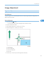
4. Select the "Registration", and then press "OK" key.
(1): Feed Direction
(2): Vertical Adjustment
(3): Horizontal Adjustment
(4): Print Area
5. Press the "Up" or "Down" keys to set the registration value (mm).
85
4. Replacement and Adjustment
• Increase the value to shift the print area in the plus direction.
• Decrease to shift in the minus direction.
6. Adjust the margins of the test page so that they are equal in size.
4
86
5. System Maintenance Reference
Service Program Mode
Overview
This model has several service menus. Each service menu has several adjustment items. This section explains
how to enter each service menu and what you can do in each service menu.
Maintenance Mode Menu
5
Selecting an Item
To select an item, press the "Up" or "Down" key.
Going into the Next Level/ Returning to the Previous Level
• To go into the next level of an item, select an item then press the "OK" key.
• To return to the previous level of an item, press the "Return" key.
Exiting the Maintenance Mode Menu
To exit the maintenance mode menu, press the "Clear/Stop" or "Return" key until the "Ready" display
appears.
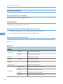
Menu List
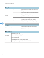
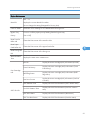
Display Info
Displays the Model Name, Depends on Engine
Firmware Settings
Model Name
FW Ver.
CTL FW Ver.
Displays the Firmware Version
FAX FW Ver.
Displays the FAX Firmware Version.
Engine FW Version
Displays the Engine Firmware Version
PDL FW Ver.
Displays the PDL Firmware Version.
87
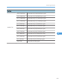
5. System Maintenance Reference
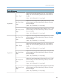
Display Info
Printer Counter
Scanner Counter
Counter
Displays the following counters of the printer engine.
Total Page
Displays the sum total of scanner counters for each
mode.
Total Page/ Black Page/ Color Page
/ ADF Used
Displays the number of paper jams at each location.
Jam Counter
5
Total/ ADF/ Outer/ Inner/ Tray1 Misfeed/
Tray2 Misfeed/ Duplex Misfeed/ Bypass Tray
Misfeed
Print Reports
G3 Protocol dump list
G3 protocol dump of the latest communication is
printed.
Off (Default)/ Error/ On
Engine Maintenance
NA Model: RICOH/ 'nul'
PNP Name
EU Model: RICOH/ NRG/ LANIER
ASIA Model: RICOH/ LANIER
China Model: RICOH
Destination
88
Sets the destination and updates the engine setting.
JPN/ NA/ EU (Default)/ ASIA/ China/ TAIWAN/ COREA
Service Program Mode
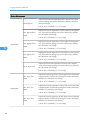
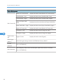
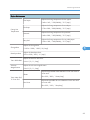
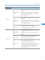
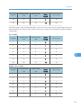
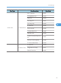
Engine Maintenance
Horiz. Tray1
Adjusts the horizontal registration for tray 1. If the machine
settings are reset to the factory defaults, this value does not
change.
[-40 to 40 / 0 (Default) / 0.1 mm/step]
Registration
Vert. Tray1 Plain
Paper
Adjusts the vertical registration of plain paper for tray1. If the
machine settings are reset to the factory defaults, this value
does not change.
[-40 to 40 / 0 (Default) / 0.1 mm/step]
Vert. Tray1 Thick
Paper
Adjusts the vertical registration of thick paper for tray 1. If the
machine settings are reset to the factory defaults, this value
does not change.
[-40 to 40 / 0 (Default) / 0.1 mm/step]
Vert. Tray1 Thin
Paper
5
Adjusts the vertical registration of thin paper for tray 1. If the
machine settings are reset to the factory defaults, this value
does not change.
[-40 to 40 / 0 (Default) / 0.1 mm/step]
Horiz. Tray2
Adjusts the horizontal registration for tray 1. If the machine
settings are reset to the factory defaults, this value does not
change.
[-40 to 40 / 0 (Default) / 0.1 mm/step]
Registration
Vert. Tray2 Plain
Paper
Adjusts the vertical registration of plain paper for tray 2. If the
machine settings are reset to the factory defaults, this value
does not change.
[-40 to 40 / 0 (Default) / 0.1 mm/step]
Vert. Tray2 Thin
Paper
Adjusts the vertical registration of thin paper for tray 2. If the
machine settings are reset to the factory defaults, this value
does not change.
[-40 to 40 / 0 (Default) / 0.1 mm/step]
Vert. Tray2 Thick
Paper
Adjusts the vertical registration of thick paper for tray 2. If the
machine settings are reset to the factory defaults, this value
does not change.
[-40 to 40 / 0 (Default) / 0.1 mm/step]
89
5. System Maintenance Reference
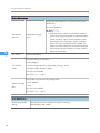
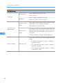
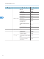
Engine Maintenance
Horiz.Bypass
Adjusts the horizontal registration for the bypass tray. If the
machine settings are reset to the factory defaults, this value
does not change.
[-40 to 40 / 0 (Default) / 0.1 mm/step]
Vert. Bypass Plain
Paper
Adjusts the vertical registration of plain paper for the bypass
tray. If the machine settings are reset to the factory defaults,
this value does not change.
[-40 to 40 / 0 (Default) / 0.1 mm/step]
5
Registration
Vert. Bypass Thick
Paper
Adjusts the vertical registration of thick paper for the bypass
tray. If the machine settings are reset to the factory defaults,
this value does not change.
[-40 to 40 / 0 (Default) / 0.1 mm/step]
Vert. Bypass Thin
Paper
Adjusts the vertical registration of thin paper for t the bypass
tray. If the machine settings are reset to the factory defaults,
this value does not change.
[-40 to 40 / 0 (Default) / 0.1 mm/step]
Horiz. Dup. Back
Adjusts the horizontal registration the back side in duplex
mode. If the machine settings are reset to the factory defaults,
this value does not change.
[-40 to 40 / 0 (Default) / 0.1 mm/step]
Vert. Dup. Plain
Paper
Adjusts the vertical registration of plain paper for the back side
in duplex mode. If the machine settings are reset to the factory
defaults, this value does not change.
[-40 to 40 / 0 (Default) / 0.1 mm/step]
Registration
Vert. Dup. Thin
Paper
Adjusts the vertical registration of thin paper for the back side
in duplex mode. If the machine settings are reset to the factory
defaults, this value does not change.
[-40 to 40 / 0 (Default) / 0.1 mm/step]
Vert. Dup. Thick
Paper
Adjusts the vertical registration of thick paper for the back side
in duplex mode. If the machine settings are reset to the factory
defaults, this value does not change.
[-40 to 40 / 0 (Default) / 0.1 mm/step]
90
Service Program Mode
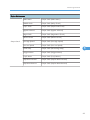
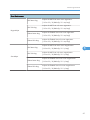
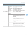
Engine Maintenance
00* – 7F
Brand ID
Displays the current brand ID number.
Do not change this setting (Designed for Factory Use).
Fuser SC Reset
This button is for resetting an SC related with the fusing errors.
Bypass Tray
Priority
Turns on or off the paper priority feeding from the bypass tray.
[On or Off]
Reset Transfer
Roller Life
Clears the EM counter of the transfer roller.
Reset Paper
Feed Roller Life
Clears the EM counter of the paper feed roller.
Reset Fusing Unit
Clears the EM counter of the fusing unit.
Life
Motor Rotation
Time
Print Cartridge
Info
OPC Life Info
5
Displays the main motor rotation time.
Kind ID
Displays the toner cartridge (AIO) information (Kind ID).
Toner End History
Displays the toner cartridge (AIO) information (Toner
End History).
Refill Flag Status
Displays the toner cartridge (AIO) information (Refill
flag status).
Unit Print Counter
Displays the toner cartridge (AIO) information (Unit Print
Counter).
OPC Rotation Time
Displays the OPC life information (OPC rotation time).
Pre-OPC Rotation Time
Displays the OPC life information (Pre-OPC rotation
time)
OPC Alert Status
Displays the OPC life information (Alert status)
OPC Pre-Alert Status
Displays the OPC life information (Pre-Alert status)
91
5. System Maintenance Reference
Engine Maintenance
Remain of Transfer Roller
Displays the total counter (Remain of Transfer Roller).
Transfer Roller - Time
Displays the EM counter (Transfer Roller: Time).
Transfer Roller - Pages
Displays the EM counter (Transfer Roller: pages).
Remain of Paper Feed
EM Counter Info Roller
5
Paper Feed Roller - Pages
Displays the EM counter (Paper Feed Roller: pages).
Remain of Fusing Unit
Displays the total counter (Remain of Fusing Unit).
Fusing Unit - Time
Displays the EM counter (Fusing Unit: time).
Fusing Unit - Pages
Displays the EM counter (Fusing Unit: pages).
Total Counter
Info
Engine Counter
Displays the total counter (Engine).
Clear Engine
Memory
Resets the engine settings stored in the EEPROM to factory default.
SC559
Detection
[On or Off (Default)]
EM Life Display
92
Displays the total counter (Remain of Paper Feed Roller).
Sets the display of alert when each EM parts yield of this machine is reached.
[On or Off (Default)]
Service Program Mode
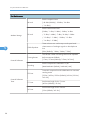
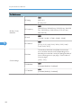
Engine Maintenance
Output check
Main Motor
Output check (Main Motor)
Middle clutch
Output check (Relay Clutch)
Tray1 clutch
Output check (Paper Feed Clutch)
Bypass solenoid
Output check (Bypass solenoid)
Regist clutch
Output check (Registration Clutch)
Reserve clutch
Output check (Reserve clutch)
Fan High Speed
Output check (Fan High Speed)
Fan Low Speed
Output check (Fan Low Speed)
Erase Lamp
Output check (Quenching Lamp)
Polygon Motor
Output check (Polygon Motor)
Tray2 Motor
Output check (Tray2 Motor)
Dup Motor Normal
Output check (Duplex Motor Normal)
Dup Motor Reserve
Output check (Duplex Motor Reverse)
5
93
5. System Maintenance Reference
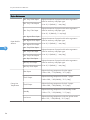
Engine Maintenance
Vert. Tray1 Plain Paper
Adjusts the amount of paper buckle at the registration
roller for each tray and paper type.
Vert. Tray1 Thick Paper
[-8 to 8 / 0 (Default) / 1 mm/step]
Vert. Tray1 Thin Paper
Adjusts the amount of paper buckle at the registration
roller for each tray and paper type.
[-8 to 8 / -2 (Default) / 1 mm/step]
Vert. Bypass Plain Paper
Paper Buckle
Amount
5
Adjusts the amount of paper buckle at the registration
Vert. Bypass Thick Paper roller for each tray and paper type.
Vert. Bypass Thin Paper
Vert. Tray2 Plain Paper
Vert. Tray2 Thin Paper
Vert. Tray2 Thick Paper
Vert. Dup. Plain Paper
Vert.Dup. Thin Paper
Vert Dup. Thick Paper
Plain Paper
Thick1 Paper
Fusing Unit
Temperature
Thick2 Paper
Standby
Low Power
94
[-8 to 8 / 0 (Default) / 1 mm/step]
Adjusts the amount of paper buckle at the registration
roller for each tray and paper type.
[-8 to 8 / 0 (Default) / 1 mm/step]
Adjusts the amount of paper buckle at the registration
roller for each tray and paper type.
[-8 to 8 / 0 (Default) / 1 mm/step]
Adjusts the fusing temperature for plain paper.
[150 to 190 / 175 (Default) / 5°C/step]
Adjusts the fusing temperature for thick 1 paper.
[160 to 200 / 185 (Default) / 5°C /step]
Adjusts the fusing temperature for thick 2 paper.
[160 to 200 / 185 (Default) / 5°C/step]
Adjusts the fusing temperature in the standby mode.
[120 to 175 / 155 (Default) / 1°C/step]
Adjusts the fusing temperature in the low power mode.
[80 to 135 / 120 (Default) / 5°C/step]
Service Program Mode
Engine Maintenance
Thin Paper
Envelope
Fusing Unit
Temperature
Postcard
Recycled
Charge Bias
Developer Bias
Trans. Roller Bias
Subscan
Magnification
Adjusts the fusing temperature for thin paper.
[140 to 165 / 150 (Default) / 5°C/step]
Adjusts the fusing temperature for envelope.
[170 to 200 / 200 (Default) / 5°C/step]
Adjusts the fusing temperature for postcard.
[160 to 200 / 185 (Default) / 5°C/step]
Adjusts the fusing temperature for recycled paper.
[150 to 180 / 160 (Default) / 5°C/step]
Adjusts the charge bias.
[1100 to 1300 / 1200 / 20 /step]
5
Adjusts the developer bias.
[270 to 330 / 300 / 15 /step]
Adjusts the transfer roller bias.
[-6 to 6 / 0 / 1 /step]
Adjusts the sub scan magnification.
[-8 to 8 / 0 / 1 /step]
Sheets
Adjusts the printable sheets between "toner near end" to
"toner end".
[0 to 255 / 200 / 1 sheet/step]
Toner Near End
To Toner End
Dot Count
Adjusts the printable dot count between "toner near end"
to "toner end".
[0 to 255 / 100 / 1 dot/step]
95
5. System Maintenance Reference
Engine Maintenance
Sets the machine operation at "waste toner full" of the
refilled AIO.
[On or Off (Default)]
5
Waste toner
disposal
Independent-Supply
Toner
Test Pattern
Prints the test pattern.
• With main motor rotation count feature, machine
can be set to stop printing after print total exceeds a
certain set value. If print count exceeds this value,
then "Replace Print Cartridge" remains in display.
Then a new AIO cartridge must be installed. This
feature is a safety measure to prevent the used toner
tank from becoming full (there is no toner overflow
detection mechanism).
Corrects the face curl of paper.
0: OFF (28ppm)
Curl Control
mode
1: Sets the engine speed at 14ppm after printing 1 minute.
2: Sets the engine speed at 14ppm.
3 to 255: not available
[0 to 255 / 0 / 1 /step]
Charge bias correction for dirty background
0: OFF (Default)
Adjust of Charge
1: ON
Bias
2 to 255: not available
[0 to 255 / 0 / 1 /step]
Scan Maintenance
Mono Compression
Setting
96
Sets the monochrome compression type for scanning.
MH (Default)/ MR/ MMR
Service Program Mode
Scan Maintenance
ADF Main Reg.
ADF Sub Reg.
Regist Adjust
Flatbed Main Reg.
Flatbed Sub Reg.
ADF Main Reg.
ADF Sub Reg.
Size Adjust
Flatbed Main Reg.
Flatbed Sub Reg.
Adjusts the ADF Scan main-scan registration.
[-2.0 to 2.0 / 0 (Default)/ 0.1 mm/step]
Adjusts the ADF Scan sub-scan registration.
[-2.0 to 2.0 / 0 (Default)/ 0.1 mm/step]
Adjusts the Flatbed Scan main-scan registration.
[-2.0 to 2.0 / 0 (Default)/ 0.1 mm/step]
Adjusts the Flatbed Scan sub-scan registration.
[-2.0 to 2.0 / 0 (Default)/ 0.1 mm/step]
Adjusts the ADF Scan main-scan magnification.
[-0.9 to 0.9 / 0 (Default)/ 0.1 %/step]
5
Adjusts the ADF Scan sub-scan magnification.
[-0.9 to 0.9 / 0 (Default)/ 0.1 %/step]
Adjusts the Flatbed Scan main-scan magnification.
[-0.9 to 0.9 / 0 (Default)/ 0.1 %/step]
Adjusts the Flatbed Scan sub-scan magnification.
[-0.9 to 0.9 / 0 (Default)/ 0.1 %/step]
97
5. System Maintenance Reference
Fax Maintenance
Sets the reception level.
RX Level
[-43 dBm (Default)/ -33 dBm/ -26 dBm
/ -16 dBm]
Sets the transmission level.
[0 dBm/ -1 dBm/ -2 dBm/ -3 dBm/ -4 dBm
Modem Settings
TX Level
/ -5 dBm/ -6 dBm/ -7 dBm/ -8 dBm/ -9 dBm
/ -10 dBm/ -11 dBm/ -12 dBm/ -13 dBm
/ -14 dBm/ -15 dBm]
5
Cable Equalizer
[0Km (Default)/ 1.8Km/ 3.6Km/ 7.2Km]
Training Retries
Encoding
T0 Timer
Protocol Definition
Timer
This sets the number of training retries to be repeated
before automatic fallback.
[1 Time/ 2 Times (Default)/ 3 Times/ 4 Times]
Protocol Definition
T1 Timer
T4 Timer
98
These selectors are used to improve the pass-band
characteristics of analogue signals on the telephone
line.
Sets the compression method for Tx/Rx.
[MMR+MR+MH (Default)/ MR+MH/ MH]
Timeout for response from the called station in automatic
sending mode
[35 Sec/ 45 Sec/ 55 Sec (Default)/ 60 Sec/ 90 Sec/
140 Sec]
Set the time length for the T1 timer.
[40 Sec (Default)/ 50 Sec]
Set the time length for the T4 timer.
[3 Sec (Default/ 4.5 Sec]
Service Program Mode
Fax Maintenance
Silence (No tone) detection time (Rx mode : FAX/ TAD
Only)
Silence Detection
Time
After the line is connected via the external telephone,
the machine can detect silence (no tone) for the time
length specified by this setting.
[30 sec (Default)]
CNG tone detection time ( RX mode : FAX / TEL, FAX /
TAD Only)
RX Settings
CNG Tone
Detection Time
After the line is connected via the external telephone,
the machine can detect a CNG signal for the time length
specified by this setting.
[5 Sec (Default)/ 10 Sec]
5
Number of CNG cycles to be detected
CNG Cycles
This setting is only effective for FAX/TAD mode.
[1.5 Cycle (Default)/ 2.0 Cycle]
Tone Sound
Monitoring
Stop/Clear key
Determines the period when tones from the line are
monitored.
[No Monitoring/ Up To Phase B (Default)/ All TX
Phases]
Pressing the Stop/Clear key can stop the current
receiving operation. Received data is lost.
[Not Functional (Default)/ Functional]
RX Settings
Sets the off-hook detection threshold.
[10V (Default)/ 15V/ 20V/ 25V 35V]
Off-Hook Level
"Telephone" was indicated by malfunction when
receiving the fax message with some PABX. Some PABX
may output more than 25V to the FAX input line.
Selecting [35V] for [Off-hook level] by the fax
maintenance mode.
99
5. System Maintenance Reference
Fax Maintenance
Redial Interval
TX Settings
Redialings
Overseas Comm
Mode
Overseas Comm
Mode Settings
Minimum Time
Length
5
Sets the redial interval when Tx fails.
[5 Min/ 6 Min]
Sets the number of redials when Tx fails.
[2 times/ 3 Times/ 4 Times/ 5 Times]
This sets the machine to ignore a DIS signal sent from the
called station once in a sending operation.
[Off (Default)/ Ignore DIS Once]
If this setting is set to "On", the machine detects the CNG
signal after the line is connected. If it is set to "Off", the
machine detects the CNG signal as long as the line is
connected.
[100 Ms/ 200 Ms/ 300 Ms/ 400 Ms (Default)]
This sets the number of pulses that are generated during
dialing.
Dial Pulse Setting
Dial Pulse Type
• N: Dialing '0' generates 10 pulses --- Dialing '9'
generates 9 pulses.
• N+1: Dialing '0' generates 1 pulses --- Dialing '9'
generates 10 pulses.
• 10-N: Dialing '0' generates 10 pulses --- Dialing
'9' generates 1 pulse.
100
Service Program Mode
Fax Maintenance
Tone Signal Settings
Tone Signal
Transmission Time
Length
Sets the tone signal transmission time length
Minimum Pause In
Tone Dialing
Sets the minimum pause during tone dialing
[100 ms (Default)]
[100 ms (Default)/ 150 ms/ 200 ms]
Attenuator For
Sets the attenuator for pseudo ringback tone to the line
Pseudo Ring
Backtone To the Line [0 to 15 / 10 (Default)/ 1 dB/step]
DTMF Level
DTMF Delta
Sets the transmission level of DTMF tones.
[-12 dBu / -11 dBu/ -10 dBu/ -8 dBu/ -6 dBu]
Sets the level difference between high band frequency
signals and low band frequency signals when sending
DTMF tones.
5
[2 dBu/ 3 dBu]
The machine starts dialing after the specified interval
without detection of a dial tone when
Wait Time
Dial tone detection is set to "No detection".
[3.5 Sec (Default)/ 7.0 Sec/ 10.5 Sec
/ 14.0 Sec]
1Dial Tone Detection
Timeout Length
This setting sets the time-out length for the 1st dial tone
detection. The machine waits for a dial tone for the
specified time and disconnects itself from the line when
no dial tone is input.
[10 Sec (Default)/ 15 Sec/ 20 Sec/ 30 Sec]
101
5. System Maintenance Reference
Fax Maintenance
DFU
BT Setting
[Off/ On]
BT: Busy tone
DFU
BT (Busy Tone)
Detection
BT Frequency
BT Level
DFU
[-35 dB/ -36 dB/ -37 dB/ -38 dB/ -39 dB]
DFU
5
BT Cadence
RTN Rate
[0.10/ 0.15/ 0.20/ 0.25/ 0.30/ 0.35/ 0.40/
0.45/ 0.50/ 0.75]
The machine checks the actual data reconstruction
errors and then transmits an RTN depending on the
decoding error rate that is set by this setting (Number of
lines containing an error per page / Total number of
lines per page).
[10%/ 15%]
Comm Settings
V34 Modem
V17 Modem
102
[300-550 Hz/ 300-650 Hz/ 325-525 Hz/ 340-550
Hz/ 350-500 Hz/ 350-550 Hz/ 375-475 Hz/
380-520 Hz]
DFU
[Permitted (Default)/ Prohibited]
DFU
[Permitted (Default)/ Prohibited]
Service Program Mode
Fax Maintenance
Equalizer
These selectors set the equalizer's training level to be
applied if training fails due to poor line connection.
[Automatic (Default)/ 4 Points/ 16 Points]
Redialing
Resend when a communication error occurs.
[Disabled (Default)/ Not Disabled]
Sets the first transmission speed choice, before fallback.
V34 Settings
[2400 Bps/ 4800 Bps/ 7200 Bps/ 9600 Bps
First TX Speed
/ 12000 Bps/ 14400 Bps/ 16800 Bps/ 19200 Bps/
21600 Bps/ 24000 Bps/ 26400 Bps/ 28800 Bps/
31200 Bps/ 33600 Bps (Default)]
This setting limits the transmission speed range in V.34
mode by masking the desired symbol rate(s).
Symbol Rate
5
[Not Used (Default)/ 3429 Sym/Sec
/ 3200 Sym/Sec/ 3000 Sym/Sec
/ 2800 Sym/Sec/ 2400 Sym/Sec]
Factory Default
Not Execute
Does not execute anything. Returns to an upper level.
Resets all the settings to factory default.
Factory Default
Execute
• Clears/ resets the contents of the controller board
memory (all data programmed by the user, log
data) to factory default.
After executing, initial setup menu starts after power-on.
CTL Maintenance
CTL Maintenance
PDL Mode
ON = "PDL Settings" is shown (Default)
OFF = "PDL Settings" is hidden
103
5. System Maintenance Reference
Fax Service Test Menu
Entering the Fax Service Test Menu
Turn on the machine while pressing the "Fax" key.
Selecting an Item
To select the item, press the "Up" or "Down" key.
Going into the Next Level/ Returning to the Previous Level
• To go into the next level of an item, select an item then press the "OK" key.
5
• To return to the previous level of an item, press the "Return" key.
Exiting the Maintenance Mode Menu
To exit the maintenance mode menu, press the "Clear/Stop" or "Return" key until the "Ready" display
appears.
Menu List
Fax Test
Off-Hook Test
On Hook
Executes the on hook test.
Off Hook
Executes the off hook test
CED Test
CNG Test
1100 Hz
Executes the CNG test
ANSam
Executes the ANSam test.
Ring Tone Test
Executes the ring tone test.
DTMF Test
104
Executes the CED test.
Tone [0] to [9]
Executes the DTMF tone 0 to 9 test.
Tone [*]
Executes the DTMF tone * test.
Tone [#]
Executes the DTMF tone # test.
Tone Stop
Executes the Stop DTMF tone test.
Service Program Mode
Fax Test
Modem Test
[V34] 33600 bps
Generates the [V34] 33600 bps signal.
[V34] 28800 bps
Generates the [V34] 28800 bps signal.
[V17] 14400 bps
Generates the [V17] 14400 bps signal.
[V17] 12000 bps
Generates the [V17] 12000 bps signal.
[V17] 9600 bps
Generates the [V17] 9600 bps signal.
[V17] 7200 bps
Generates the [V17] 7200 bps signal.
[V29] 9600 bps
Generates the [V29] 9600 bps signal.
[V29] 7200 bps
Generates the [V29] 7200 bps signal.
[V27] 4800 bps
Generates the [V27] 4800 bps signal.
[V27] 2400 bps
Generates the [V27] 2400 bps signal.
[V21] 300 bps
Generates the [V21] 300 bps signal.
Signal Stop
Generates the Stop signal.
5
105
5. System Maintenance Reference
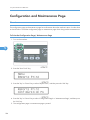
Configuration and Maintenance Page
Overview
The configuration page and maintenance page have information about the machine's status. Print this sheet
as shown below. Check the configuration page or maintenance page when doing machine maintenance.
To Print the Configuration Page/ Maintenance Page
1. Turn on the machine.
5
2. Press the "User Tools" key.
3. Press the "Up" or "Down" key to select "Reports Print", and then press the "OK" key.
4. Press the "Up" or "Down" key to select "Configuration Page" or "Maintenance Page", and then press
the "OK" key.
5. The configuration page or maintenance page is printed.
106
Configuration and Maintenance Page
Other Types of Reports
You can also check other reports than two reports (configuration page and maintenance page) with "Report
Print" in the "Menu".
• Activity Report
Prints a fax transmission and reception report for the last 100 jobs.
• Memory List
Prints a list of unsent fax jobs remaining in the machine's memory.
• Quick Dial List
Prints a list of scan and fax Quick Dial entries.
• Speed Dial List
Prints a list of Speed Dial entries.
- No Sort
Prints the list with the entries sorted by Speed Dial registration number.
- Sort By Name
Prints the list with the entries sorted by name.
5
• Scan Directory List
Prints a list of scan destinations.
• Scan Transmission Log
Prints a scan transmission report.
Total Counter
Total Counter:
The total counter incremented by the "engine controller board" each time the board issues a print command
to the engine.
The value is calculated as follows:
Total counter = Copier counter + Printer counter + FAX counter + Reports print
Application Counters:
Application counters exist for each individual primary machine function (Copier, Printer, FAX, etc.), and
are incremented by the "controller board" each time the board issues a print request for the function in
question.
107
5. System Maintenance Reference
Firmware Updating
• Never turn the machine's main power off while the firmware is being updated, as this could damage
the ECB or controller board.
Checking the Machine Firmware Version
To update the firmware for this machine, you need the most recent version of the firmware (firmware file
downloadable from the Internet).
1. Turn the machine's main power on.
2. Press "User/Tool" Key and select "Reports Print" with the "Up" or "Down" key.
5
3. Press "OK" and select "Maintenance Page" with the "Up" or "Down" key.
4. Press "OK" to print the "Maintenance Page", which shows the "Firmware Version (Controller)" and
"Engine FW version".
Updating the Controller Firmware
Using the following procedure to update the controller firmware, be sure to print the configuration page
both before and after the update. Comparing pre- and post-update configuration pages allows you to
check whether or not the update was successful.
Follow the procedure carefully, and note that it will vary in parts depending on which version of the firmware
is currently installed.
Procedure
When updating firmware, always disconnect any other cable(s) than the one being used for the update
operation.
(When updating firmware via USB cable, first disconnect any network and phone line cables, and when
updating firmware via LAN cable, first disconnect any USB and phone line cables.)
1. Prepare:
• Computer
• USB cable or LAN (Local Area Network) cable
2. Download the firmware files to your computer.
108
Firmware Updating
3. Make a folder on a local drive of your computer and save the files there.
• "FWUpdate ToolSP.exe": Used for Controller firmware or Engine firmware
• "FWUpdate Tool.exe": Used for Controller firmware
4. Connect a USB cable between a computer and the machine.
5. Click the "FWUpdateToolSP.exe" or "FWUpdateTool.exe" file to execute the updating program.
5
6. For a USB connection, click "F/W Update (USB)" [A]. For a network connection, enter the machine's
IP address in "MFP IP Address" [B], and then click "F/W Update (NET)" [C].
7. The message "Download complete" appears.
• Do not turn the main power off from this point until the update procedure is completed.
8. The following message appears on the screen:
"Firmware is Updating ..."
9. Wait until the update is finished.
• Do not touch the machine during updating!
109
5. System Maintenance Reference
10. The update is finished when "Firmware Update Done. Please Reboot" appears on the operation
panel's display.
11. Turn the main power of the machine off, and then turn it back on.
12. Print a configuration page to check the machine's firmware version.
Updating the Engine Firmware
Procedure
When updating firmware, always disconnect any other cable(s) than the one being used for the update
operation.
5
(When updating firmware via USB cable, first disconnect any network and phone line cables, and when
updating firmware via LAN cable, first disconnect any USB and phone line cables.)
1. Prepare:
• PC
• USB cable or network cable
2. Download the firmware file to your computer.
3. Make a folder on a local drive of your computer and save the files there.
4. Connect a USB cable between your computer and the machine.
5. Click the "FWUpdateToolSP.exe" file to execute the updating program.
110
Firmware Updating
5
6. The above updating program should appear on the screen.
7. For a USB connection, click "Eng. F/W Update (USB)" [A]. For a network connection, enter the
machine's IP address in "MFP IP Address" [B], and then click "Eng. F/W Update (NET)" [C].
8. The update is in progress when "Firmware is Updating" appears.
• You will see the progress percentage appear while the update is in progress.
• Do NOT turn the main power of the machine off during updating.
111
5. System Maintenance Reference
9. The update is finished when "Firmware Update Done. Please Reboot Engine." appears.
10. Turn the main power of the machine off, and then back on.
Updating the Boot Loader Firmware
This is also listed on the configuration page, but this firmware is not updated in the field.
Updating Failure
5
If the firmware update is not successful, the update process is suspended and an error message should
display on the FW Update Tool screen. If this happens, DO NOT turn off the machine, and execute the
update procedure again (unless the error message "Downloaded file is broken! Do NOT use print, scan,
fax and copy function at the same time." is displayed).
If power is turned off accidentally during a firmware update, the firmware will not be correctly updated,
and the machine may not start up normally. If the machine does not start up normally, the controller firmware
and/or the engine firmware will need to be updated again.
When the machine does not start up normally, in most cases, the panel display will indicate one of the
following two conditions:
• When attempting to restart the machine, the LCD panel display indicates "Initializing" indefinitely.
In this case, the controller firmware update has failed. The controller firmware must be updated again.
• When attempting to restart the machine, the LCD panel display indicates "Please Download Engine
FW Again!"
In this case, the engine firmware update has failed. The engine firmware must be updated again.
FW Update Tool Messages
FW Update Tool Messages: Information
Message for USB update
Messages
USB Upload : End of data
112
Comment
Action
Send F/W file to MFP successfully.
Please reboot MFP after panel
shows reboot message.
(Transmission Time: <30 sec)
Firmware Updating
Messages
Comment
Action
Check USB cable connection.
USB Upload : FAIL
Can not open USB printer driver
while F/W file is transmitted.
F/W file transmission can not be
completed.
(Transmission will be canceled if
timeout.)
Can't open ROM file.Please
check ROM file.
F/W file does not exist.
Check the installation of USB
Print Driver if it is available.
Check MFP status if it is
available.
Check USB cable connection.
Check USB Print Driver if it is
available.
Check MFP status if it is
available.
Check the download file name
in setting.ini. "ImageFile="
5
Check the download file and fw
update tool is in the same folder.
Check the download file name
in setting.ini. "EngImageFile="
Can't open Eng. ROM file.
Please check Eng. ROM file.
Engine F/W file does not exist.
New Version: Update FW
AIO FW is transmitting
Not available
Eng FW version: Update Eng
FW
Engine FW is transmitting
Not available
Firmware is Updating...
AIO FW is updating
Not available
Eng Firmware is Updating...
Engine FW is updating
Not available
FW Update Done. *** Please
reboot the Machine.***
F/W update is completed.
Please reboot the Machine.
Check the download file and fw
update tool is in the same folder.
Message for Network update
Messages
Connecting…
Net Upload : End of data
Comment
Action
Connect to MFP.
Please wait a moment.
Update F/W successfully.
Please reboot MFP after panel
shows reboot message.
(Transmission Time: <30 sec)
113
5. System Maintenance Reference
Messages
Comment
Action
(1) Check network cable
connection.
Net Upload : FAIL
Can not open FTP port of MFP
before F/W file is transmitted.
(2) Check MFP status if it is
available.
(Transmission will be canceled if
timeout.)
(3) Check MFP and PC IP
address setting.
(4) Check PC firewall setting
about FTP.
5
Can't open ROM file. Please
check ROM file.
F/W file transmission can not be
completed.
(1) Check network cable
connection.
(Transmission will be canceled if
timeout.)
(2) Check MFP status if it is
available.
F/W file does not exist.
Check the download file and fw
update tool is in the same folder.
Check the download file name
in setting.ini. "EngImageFile="
Can't open Eng. ROM file.
Please check Eng. ROM file.
Engine F/W file does not exist.
New Version: Update FW
AIO FW is transmitting
Not available
Eng FW version: Update Eng
FW
Engine FW is transmitting
Not available
Firmware is Updating...
AIO FW is updating
Not available
Eng Firmware is Updating...
Engine FW is updating
Not available
FW Update Done. *** Please
reboot the Machine.***
F/W update is completed.
Please reboot the Machine.
FW Update Tool Messages: Error
Message for USB update
114
Check the download file name
in setting.ini. "ImageFile="
Check the download file and fw
update tool is in the same folder.
Firmware Updating
Messages
Comment
Action
Check USB cable connection.
Machine is not ready.
Wrong Model.
Machine is busy.
FW Update Done. *** Please
reboot the Machine.***
Can not get MFP status form USB
status channel before F/W file is
transmitted.
F/W file is not matched for current
machine.
F/W update is running.
Check USB Print Driver if it is
available.
Do not update F/W when MFP
is in power-on stage.
Please check the version of F/
W file and machine if it is
suitable for MFP.
Please wait F/W update is
completed.
Other MFP functions are running.
Please wait other MFP functions
are completed.
F/W update is completed.
Please reboot the Machine.
Machine loses communication.
***Please check FW Update F/W file has transmitted. Polling F/
Done. Then reboot the
W update progress fail.
Machine.***
Downloaded file is broken! Do F/W checks the downloaded file.
NOT use print, scan, fax and
And get wrong checksum. So stop
copy function at the same time. to modify F/W.
5
Do not reboot engine till Engine
Panel display "Firmware
Update Done. Please reboot".
Then reboot engine.
Check the downloaded file is
not broken.
Do not use MFP functions when
update firmware.
Message for Network update
Messages
Machine is not ready.
Comment
Can not get MFP status form
Network status channel before F/
W file is transmitted.
Action
Check PC network settings and
IP address.
Check MFP network settings
and IP address.
Do not update F/W when MFP
is in power-on stage.
115
5. System Maintenance Reference
Messages
Wrong Model.
Machine is busy.
FW Update Done. *** Please
reboot the Machine.***
5
Comment
Action
F/W file is not matched for current
machine.
Please check the version of F/
W file and machine if it is
suitable for MFP.
F/W update is running.
Other MFP functions are running.
Please wait other MFP functions
are completed.
F/W update is completed.
Please reboot the Machine.
Machine loses communication.
***Please check FW Update F/W file has transmitted. Polling F/
Done. Then reboot the
W update progress fail.
Machine.***
Downloaded file is broken! Do F/W checks the downloaded file.
NOT use print, scan, fax and
And get wrong checksum. So stop
copy function at the same time. to modify F/W.
116
Please wait F/W update is
completed.
Do not reboot engine till Engine
Panel display "Firmware
Update Done. Please reboot".
Then reboot engine.
Check the downloaded file is
not broken.
Do not use MFP functions when
update firmware.
6. Troubleshooting
Service Call Conditions
See "Appendices" for the "Error Messages".
Summary
This machine issues an SC (Service Call) code if an error occurs with the machine. The error code can be
seen on the operation panel.
Make sure that you understand the following points;
1. All SCs are logged.
2. At first, always turn the main switch off and on if an SC code is displayed.
3. First, disconnect then reconnect the connectors before replacing the PCBs (if the problem concerns
electrical circuit boards).
4. First, check the mechanical load before replacing motors or sensors (if the problem concerns a locked
motor).
6
Fusing related SCs
To prevent damage to the machine, the main machine cannot be operated until the fusing related SC has
been reset by a service representative.
• Enter the engine maintenance mode.
Press "O.K" in "Fuser SC Reset" with engine maintenance mode, and then turn the main power switch off
and on.
Engine SC
SC 2xx (Laser Optics Error)
Polygon motor on timeout error
202
The polygon mirror motor does not reach the targeted operating speed within 10 sec. after
turning.
117
6. Troubleshooting
Polygon motor off timeout error
203
The polygon mirror motor does not leave the READY status within 20 sec. after the polygon
mirror motor switched off.
Polygon motor lock signal error
The signal remains HIGH for 200 ms (or 4times in 50msec polling) while the polygon mirror
motor is rotating.
• Polygon motor/driver board harness loose or disconnected
204
• Polygon motor/driver board defective
• Laser optics unit defective
1. Turn the main power off/on the machine.
2. Replace the interface harness of the laser optics unit.
3. Replace the laser optics unit.
Beam Synchronize error
6
The laser synchronizing detection signal for LD is not output within 400msec after the LD unit
has turned on.
• Disconnected cable from the laser synchronizing detection unit or defective connection
220
• Defective laser synchronizing detector
• Defective LD
• Defective ECB
1. Check the connectors.
2. Replace the laser optics unit.
3. Replace the ECB.
Video thermistor error
At power on, the temperature sensor in the optics unit detected a temperature lower than -30°
C for more than 4 sec.
-or-
268
It detected a temperature higher than 105°C for more than 1sec.
• Thermistor disconnected (causes extremely low temperature reading)
• Thermistor damaged and short circuited (causes extremely high temperature reading)
1. Turn the machine's main power off, and then on.
2. Replace the thermistor.
118
Service Call Conditions
SC 4xx (Image Transfer and Transfer Error)
Bias leak
An error signal is detected for 0.2 seconds when changing the development unit.
491
• Defective transfer roller
• Defective high voltage power pack
1. Turn the machine's main power off, and then on.
SC 5xx (Motor and Fusing Error)
Main motor error
The machine does not detect a main motor lock signal within 2sec after the main motor started
to rotate.
-orThe machine does not release a main motor lock signal within 2sec after the main motor switched
off.
6
-or500
The machine detects a main motor lock signal every 100ms for seven times consecutively, after
the main motor started to rotate stably.
• Overload of
• Torque load overload
• Defective main motor
• Disconnect or defective motor harness
1. Turn the machine's main power off, and then on.
2. Check or replace the main motor if the torque load is normal.
3. Replace the motor harness.
Fusing Fan Motor Error
530
The FAN lock signal – High for 10 seconds, after the fan motor started to rotate.
• Disconnected or defective motor harness.
1. Turn the machine's main power off, and then on.
119
6. Troubleshooting
Fuser thermistor error
The thermistor output is less than 0°C for 5 seconds after the fusing lamp turns ON.
• Disconnected or defective thermistor
• Disconnected or defective fusing lamp
541
1. Check the harness connection of the thermistor.
2. Replace the fusing unit.
• Execute "Engine Maintenance Menu" to recover the machine after completing the recovery
procedure. Otherwise, the machine continues to
• issue this SC code and cannot be operated.
Fuser reload error
This SC is issued if one of following conditions occurs:
The fusing temperature rises 8°C or less in 1.5 seconds; and this continues 5 times consecutively.
6
-orThe fusing temperature has not reached 45°C within 9 seconds (after the fusing lamp comes
ON while the machine is warming-up).
542
-orThe fusing unit does not attain reload temperature within 35 s. (normal temperature) or 65 s
(lower temperature – the thermistor output is less than 18°C) after the fusing temperature control
starts.
• Defective or deformed thermistor
• Incorrect power supply input at the main power socket
1. Defective fusing lamp
120
Service Call Conditions
High temperature error (Software)
• The detected temperature stays at 225°C for 1 second, and this consecutively occurs 10
times.
• Defective ECB
543
• Defective PSU
1. Replace the ECB
2. Replace the PSU
• Execute "Fuser SC Reset" to recover the machine after completing the recovery procedure.
Otherwise, the machine continues to issue this SC code and cannot be operated.
High temperature error (Hardware)
• During stand-by mode or a print job, the detected heating roller temperature reaches 250°
C.
• Defective ECB
544
6
• Defective PSU
1. Replace the ECB
2. Replace the PSU
• Execute "Fuser SC Reset" to recover the machine after completing the recovery procedure.
Otherwise, the machine continues to issue this SC code and cannot be operated.
Fusing Lamp Overheat Error
The fusing lamps remained ON at full capacity for more than 9 s after the fusing temperature
attains reload temperature.
• Deformed thermistor
• Thermistor not in the correct position
545
• Defective fusing lamp
1. Replace the fusing unit.
2. Replace the fusing lamp.
• Execute "Fuser SC Reset" to recover the machine after completing the recovery procedure.
Otherwise, the machine continues to issue this SC code and cannot be operated.
121
6. Troubleshooting
Zero cross error
• The zero cross signal is detected three times even though the fusing lamp relay is off when
turning on the main power.
• The zero cross signal is not detected for 3 seconds even though the fusing lamp relay is
on after turning on the main power or closing the front door.
• The detection error occurs twice or more in 11 zero cross signal detections. This error is
defined when the detected zero cross signal is less than 45.
547
• The zero cross signal is not detected three times while the main power remains ON.
• Defective fusing relay
• Defective fusing relay circuit
• Shorted +24V fuse on the PSU
• Unstable power supply.
1. Check the power supply source.
2. Replace the +24V fuse on the PSU.
6
3. Replace the PSU
Zero cross frequency error
The zero cross signal is detected ten times while the fusing lamp relay remains ON after turning
on the main power.
• Defective fusing lamp relay
• Defective drive circuit of the fusing lamp relay
557
• Unstable input power source
1. Check the power supply source.
2. Replace the fusing unit.
• Execute "Fuser SC Reset" to recover the machine after completing the recovery procedure.
Otherwise, the machine continues to issue this SC code and cannot be operated.
122
Service Call Conditions
Fuser 3times jam error
The paper jam counter for the fusing unit reaches 3. The paper jam counter is cleared if the
paper is fed correctly.
This SC is activated only when this function is enabled with "Engine Maintenance" (default
"OFF").
559
• Defective fusing unit
• Defective fusing control
1. Clear this SC to send a command after a jam removal.
2. Turn off this function after a jam removal.
• Execute "Fuser SC Reset" to recover the machine after completing the recovery procedure.
Otherwise, the machine continues to issue this SC code and cannot be operated.
SC 6xx (Communication and Other Error)
6
EEPROM communication error
An unexpected value exists in the initialization flag of the EEPROM
669
• EEPROM not connected
• Defective EEPROM
1. Installing the EEPROM.
2. Replacing the EEPROM.
CTL_PRREQ_N signal does not come.
The ECB does not receive a memory address command from the controller 20 seconds after
paper is in the position for registration.
688
• Defective controller board
• Communication error
1. Turn the machine's main power off, and then on.
2. Check if the controller board is firmly connected to the ECB.
123
6. Troubleshooting
Image Problems
Overview
Image problems may appear at regular intervals that depend on the circumference of certain components.
The following diagram shows the possible symptoms (black or white dots at regular intervals).
6
• Abnormal image at 29.8 mm intervals: Charge roller
• Abnormal image at 37.7 mm intervals: Registration roller
• Colored spots at 37.9 mm intervals: Print cartridge (Development roller)
• Abnormal image at 45.8 mm intervals: Transfer roller
• Colored spots at 75.3 mm intervals: Print cartridge (OPC drum)
• Abnormal image at 94.2 mm intervals: Fusing unit (Pressure roller)
• Abnormal image at 93.1 mm intervals: Fusing unit (Hot roller)
• Abnormal image at 100.5 mm intervals: Paper feed roller
Test Page Printing
When you check an image problem or other problems, it might be necessary to print a test page. Follow
the test page print procedure below to print a test page.
Test Page Print Procedure
1. Press the "User Tools".
2. Press the "Up" or "Down" keys to select "PDL Settings" and then press the "OK" key.
3. Press the "Up" or "Down" keys to select "List Print" and then press the "OK" key.
124
Image Problems
4. Press the "Up" or "Down" keys to select "Test Page" and then press the "OK" key.
5. Press the "OK" key to print the test page to preview the settings.
• Test page sample
6
Test Pattern Printing
Follow the test pattern print procedure below to print a test pattern.
Test Pattern Print Procedure
1. Enter the "Maintenance Mode".
2. Select "Engine Maintenance", and then press "OK" key.
3. Select "Test Pattern", and then press "OK" key.
4. The following three test pattern pages (Checker flag/ Grid pattern/ Trimming pattern) are printed.
• Test pattern samples
125
6. Troubleshooting
Dark lines in halftone areas at 75mm Intervals
6
Using the machine in a room where humidity level is too low may cause dark lines in halftone areas at
75mm intervals. This is because low-humidity conditions tend to cause variations in light sensitivity across
the surface of the drum.
Selecting [On] for [Low Humidity Mode] under [Machine Settings] may help to prevent these lines from
appearing.
When the humidity mode setting is enabled, the drum is rotated slightly every 15 minutes. This keeps the
light sensitivity constant across the entire surface of the drum.
126
Jam
Jam
Jam Sensor Layout
There are the sensors of the jam detection as shown below.
Paper Jam
6
1. Registration Sensor
2. Tray2 Paper Feed Sensor
3. Inverter Sensor
4. Paper Exit Sensor
5. Relay Sensor
127
6. Troubleshooting
Original Jam
1. ADF Feed Sensor
2. Original Set Sensor
6
Jam Message List
Here is a list of common jam messages, a description of the causes.
See the drawing shown above to check the sensor location.
Paper Jam
Related to jam code
Jam message
Sensor
Bypass Tray Paper Misfeed Jam
Paper does not reach registration
Registration sensor [1]
sensor (bypass tray)
Upper Misfeed Jam
Paper does not reach registration
Registration sensor [1]
sensor (tray1)
Lower Misfeed Jam
128
Cause
Paper does not reach tray2
convey sensor
Tray2 paper feed sensor [2]
Paper does not reach registration
Registration sensor [1]
sensor
Jam
Paper does not reach registration
Registration sensor [1]
sensor (duplex feed tray)
Duplex Jam Duplex Misfeed Jam
Paper does not reach duplex
entry sensor
Relay sensor [5]
Paper does not reach duplex exit
Inverter sensor [3]
sensor
Paper stayed on registration
sensor
Inner Jam
Registration sensor [1]
Paper does not reach exit sensor Paper exit sensor [4]
Outer Jam
Paper stayed on exit sensor
Paper exit sensor [4]
Related to initialize jam
Jam message
Cause
Lower Misfeed Jam
Tray2 paper feed sensor [2]
Inner Jam
Registration sensor [1]
Outer Jam
Paper exit sensor [4]
Duplex Jam Duplex MIsfeed Jam
6
Relay sensor [5]
Inverter sensor [3]
Original Jam
Jam message
"ADF Jam Open ADF Cover and Clear Jam"
Cause
ADF Feed sensor [6]
Original set sensor [7]
129
6. Troubleshooting
6
130
7. Energy Saving
Energy Save
Energy Saver Modes
Customers should use energy saver modes properly, to save energy and protect the environment.
7
The backlight of the screen is turned off and "Energy Saver Mode1" appears on the screen, and then the
fusing lamp is turned off and "Energy Saver Mode2" appears on the screen.
The area shaded grey in this diagram represents the amount of energy that is saved when the timers are
at the default settings. If the timers are changed, then the energy saved will be different. For example, if
the timers are all set to 240 min., the grey area will disappear, and no energy is saved before 240 min.
expires.
Timer Settings
The user can set these timers with User Tools (Menu > Admin Settings > Power Saver > Energy Saver Mode1
or Mode2)
• Energy Saver Mode1 (30 sec.): This can be only turned on or off.
131
7. Energy Saving
• Energy Saver Mode2 (1 to 240 min.): This can be turned on or off and timer setting is adjustable
(default: 1min.).
Return to Stand-by Mode
Energy Saver Mode1
• Recovery time: 10 sec.
Energy Saver Mode2
• Recovery time: 23 sec.
Recommendation
We recommend that the default settings should be kept.
• If the customer requests that these settings should be changed, please explain that their energy costs
could increase, and that they should consider the effects on the environment of extra energy use.
• If it is necessary to change the settings, please try to make sure that the Energy Saver Mode2 Timer
is not too long. Try with a shorter setting first, such as 30 min., then go to a longer one (such as 60
min.) if the customer is not satisfied.
7
132
• If the timers are all set to the maximum value, the machine will not begin saving energy until 240
minutes has expired after the last job. This means that after the customer has finished using the machine
for the day, energy will be consumed that could otherwise be saved.
Paper Save
Paper Save
Effectiveness of Duplex/Combine Function
Duplexing and the combine functions reduce the amount of paper used. This means that less energy overall
is used for paper production, which improves the environment.
1. Duplex:
Reduce paper volume in half!
7
2. Combine mode:
Reduce paper volume in half!
3. Duplex + Combine:
Using both features together can further reduce paper volume by 3/4!
133
7. Energy Saving
To check the paper consumption, look at the total counter and the duplex counter.
The total counter counts all pages printed.
• For one duplex page, the total counter goes up by 2.
• For a duplex job of a three-page original, the total counter goes up by 3.
The duplex counter counts pages that have images on both sides.
• For one duplex page, the duplex counter goes up by 1.
• For a duplex job of a three-page original, the duplex counter will only increase by 1, even though
two sheets are used.
7
Total counter
This machine has a total sides printed counter only (so a duplex print is counted as two, not one). You can
check the total counter in the "Maintenance Mode" or on the "Maintenance Page".
• Total counter: "Maintenance Mode" > "Engine Maintenance" > "Total Counter In" or "Maintenance
Page"
The following table shows paper savings and how the counters increase for some simple examples of
single-sided and duplex jobs
Duplex mode:
134
Originals
Simplex Sheet
used
Duplex Sheets
used
Paper
Saved
Total counter
1
1
1
0
1
2
2
1
1
2
3
3
2
1
3
4
4
2
2
4
5
5
3
2
5
Paper Save
Originals
Simplex Sheet
used
Duplex Sheets
used
Paper
Saved
Total counter
10
10
5
5
10
20
20
10
10
20
If combine mode is used, the total and duplex counters work in the same way as explained previously. The
following table shows paper savings and how the counters increase for some simple examples of duplex/
combine jobs.
2 in 1 mode:
Originals
Simplex Sheet
used
Duplex Sheets
used
Paper
Saved
Total counter
1
1
1
0
1
2
2
1
1
1
3
3
2
1
2
4
4
2
2
2
5
5
3
2
3
10
10
5
5
5
20
20
10
10
10
7
Duplex + 2 in 1 mode:
Originals
Simplex Sheet
used
Duplex Sheets
used
Paper
Saved
Total counter
1
1
1
0
1
2
2
1
1
1
3
3
1
2
2
4
4
1
3
2
5
5
2
3
3
6
6
2
4
3
7
7
2
5
4
135
7. Energy Saving
7
136
Originals
Simplex Sheet
used
Duplex Sheets
used
Paper
Saved
Total counter
8
8
2
6
4
9
9
3
6
5
10
10
3
7
5
11
11
3
8
6
12
12
3
9
6
Model RN-MF1
Machine Codes: M016/M017
Appendices
30 November, 2009
TABLE OF CONTENTS
1. Appendix: Specifications
General Specifications.......................................................................................................................................3
General Specifications...................................................................................................................................3
Printer...............................................................................................................................................................5
Copier.............................................................................................................................................................6
Scanner...........................................................................................................................................................7
Fax...................................................................................................................................................................7
Supported Paper Sizes....................................................................................................................................10
2. Appendix: SP Mode Tables
Service Menu....................................................................................................................................................13
3. Appendix: Troubleshooting Guide
Service Call Conditions...................................................................................................................................15
Error Messages................................................................................................................................................16
Overview......................................................................................................................................................16
Error Messages List......................................................................................................................................16
Fax Error Code.............................................................................................................................................18
1
2
1. Appendix: Specifications
General Specifications
1
General Specifications
Configuration
Desktop
Main tray
250 sheets (80g/m2)
100 postcards
50 sheets (80g/m2)
Paper capacity
By-pass tray
8 envelopes
20 postcards
Optional paper feed unit Plain paper: 250 sheets (80g/m2)
Output tray
Face down: 125 sheets
A4, A5, Letter, Legal, B5, HLT, A6, Executive,
Postcard
Main tray
Custom size:
Max: 216 x 356mm (8.5 x 14 inch)
Min: 100 x 148mm (3.937 x 5.8 inch)
A4, A5, A6, Letter, Legal, HLT, Executive,
Postcard, B5, Envelope
Paper size
By-pass tray
Custom size:
Max.: 216 x 356mm (8.5 x 14 inch)
Min.: 90 x 148mm (3.5 x 5.8 inch)
Duplex
A4, Letter, Legal
Optional paper feed unit A4, LT, LG, B5, HLT, A5
3
1. Appendix: Specifications
1
Main tray
52-162 g/m2 (14-43 lb)
By-pass tray
52-162 g/m2 (14-43 lb)
60-105 g/m2 (16-28 lb)
Paper weight
Optional paper feed unit
ADF
A setting for outside of normal specifications
paper (60 g/m2 - 105 g/m2) is provided.
With this setting, it may be possible to print
properly on outside of normal specifications
paper.
Paper weight
52-105 g/m2 (14-28 lb)
Capacity
35 sheets
Width
139.7 to 216mm (5.5 to 8.5 inch)
Length
139.7 to 355.6mm (5.5 to 14 inch)
Machine size
420 x 397 x 442 mm (16.5 x 15.6 x 17.4 inch)
(W x D x H)
Without Option
M016: 17.1 Kg(37.7 lb)
Weight
M017: 18.0 Kg(39.7 lb)
• With a starter AIO cartridge.
Energy Saver Mode
Selectable 1 to 240 minutes (1 minute steps)
NA/TW: Less than 850 W
Maximum
Power consumption
Ready mode
Power save mode
Power
4
(energy star compliant)
EU/AP/CN: Less than 895 W (energy star
compliant)
120W
70 W (energy saver mode1)
10 W (energy saver mode2)
NA
120 V, 60Hz ± 3Hz
TW
110 V, 60Hz ± 3Hz
EU/AP/CN
220 - 240 V, 50/60Hz ± 3Hz
General Specifications
Noise
Printing
Less than 65.8 dB (A)
Standby Mode
Less than 40 dB (A)
Energy Save Mode
Less than 40 dB (A)
Warm up time
Less than 30 seconds
Machine life
5 years, 200,000 prints (whichever comes first)
Environmental Standard
Energy star program (M017)
Laser type
Class IIIB
1
Printer
Simplex
Print speed
Duplex
(M017 only)
Printer drivers
PCL, PS3
Font
80 fonts
Resolution
30 ppm LT, 28 ppm A4 (600 dpi)
15 ppm LT, 14 ppm A4 (600 dpi)
Normal
600 x 600 dpi
RET
1200 x 600 dpi
Toner save mode
Supported
Warm-up time
Less than 30 seconds
First print time
Less than 8 seconds
Duplex print
Supported (M017 only)
Interface option
USB 2.0, 10/ 100 Base - TX
Network
Protocol
TCP/IP, IPP
Memory
Standard
128MB
PCL: Windows XP, 2000/2003server, Vista, Windows 2008 server
Operation System
PS3: Windows XP, 2000/2003server, Vista, Windows 2008 server
Macintosh 10.2.8 -
5
1. Appendix: Specifications
Copier
1
1st copy speed
Less than 12 sec.
Maximum original size
Copy Speed
Single
Document
Multiple Copy
Multiple
Document
Single Copy
Flatbed
A4 (210 x 297mm) / Letter (215.9 x 279.4mm)
ADF
A4 (210 x 297mm) / Letter (215.9 x 279.4mm)/
Legal (215.9 x 355.6mm)
Flatbed
28 cpm (A4), 30 cpm (LT)
ADF
28 cpm (A4), 30 cpm (LT)
ADF
20 cpm
Multiple copy
Resolution (H x V)
Up to 99
Scanning
600 x 600 dpi (Flatbed), 600 x 300 dpi (ADF)
Printing
600 x 600 dpi
Grayscale
Reduction / Enlargement
256 levels
Fix
Custom
6
NA: 50, 65, 78, 93, 129, 155, 200, 400%
EU: 50, 71, 82, 93, 122, 141, 200, 400%
25 - 400% in 1% steps
Copy mode
Text/ Photo/ Mixed
Memory copy
Yes
Duplex copy
Yes (M017 only)
Interrupt copy
No
Combine copy
2 in 1, 4 in 1 (ADF only for A4/ LT)
APS/ AMS
No/No
Auto Tray Switch
No
Directional Magnification
No
Directional Size Magnification
No
General Specifications
Photo Mode
Yes
Auto Start
No
User Program
No
Electronic Sorting
Standard (collation, ADF only), Max. A4/ LT, LG
Image Rotation
No
Series Copy
No
1
Scanner
Scanning Device
CCD array image-sensor
Scanner: 1200 x 1200 dpi
Resolution
Driver: Max. 19200 x 19200 dpi (interpolated)
Gray scale
256 levels
Scan modes/ speed
(A4, 200dpi,Compression)
Maximum
original size
Less than 5 sec.
Platen
Width max: Up to 216mm, Length max: Up to 297mm
ADF
Width max: Up to 216mm, Length max: Up to 356mm
Scan Depth
48 bits color processing (input), 24 bits color processing (output)
PC Interface
USB2.0, 10/100Base-TX
TWAIN Compliment
TWAIN, WIA
Scanner utilities and Drivers
TWAIN Driver, Scanner utility (PageManager)
Fax
Network
PSTN/ PBX
Compatibility
T30 (ITU-T Super G3)
Transmission Speed
Approx. 3sec
7
1. Appendix: Specifications
1
Coding system
MH/MR/MMR
Contrast control
3 Level
Telephone Connection
Standard: One connection
Answering Machine
Interface
Standard
Monitor Speaker
3 Level
Document size
139.7 to 215.9mm (5.5" to 8.5")
ADF Length
139.7 to 355.6mm (5.5" to 14")
Flatbed Width
216mm
Flatbed Length
297mm
Scanning width
Max. 210 mm (8.3")
Printing width
Max. 208 mm (8.2")
Gray scale
256 levels
Polling type
None
Resolution
8
ADF Width
Standard: 200dpi x 100dpi (8 dot/mm x 3.85 line/mm)
Fine/Photo: 200dpi x 200dpi (8 dot/mm x 7.7 line/mm)
Scanning Speed
Less than 5 sec. (A4 SEF, 200 dpi)
Modem Speed
Automatic Fallback: 33600, 31200, 28800, 26400, 24000, 21600,
19200, 16800, 14400, 12000, 9600, 7200, 4800, 2400bps
SAF Memory
100 pages (ITU No.1 chart)
Memory Backup
1 hour
One-touch dial
20
Abbreviated dial
50
Broadcasting
100 stations
Communication source
Public switched telephone network
PC Fax utility
Available
Automatic re-dial
Available
General Specifications
Auto Answer
3-5 rings (Default 3 rings)
1
9
1. Appendix: Specifications
Supported Paper Sizes
1
A
Supported, with size molded into tray. Need to select paper size by operation panel/
driver.
B
Supported but size is not molded into tray. Need to select paper size by operation
panel/driver.
C
Need to input paper size by operation panel and driver.
N
Not supported.
Type
LEF
Input Tray
Size
Standard
Option
Bypass
Tray
PFU
Tray
Auto
Duplex
A4
SEF
210x297
A
A
B
C
B5
SEF
182x257
A
A
B
N
SEF
148x210
A
A
B
N
LEF
210x148
N
N
C
N
SEF
128x182
B
N
B
N
LEF
182x128
N
N
N
N
SEF
105x148
B
N
B
N
LEF
148x105
N
N
N
N
SEF
100 x 148
C
N
C
N
LEF
148 x 100
N
N
N
N
SEF
200 x 148
C
N
C
N
LEF
148 x 200
C
N
N
N
Legal
SEF
81/2"x14"
A
A
B
B
Letter
SEF
81/2"x11"
A
A
B
B
SEF
51/2" x 81/2"
B
B
B
N
LEF
81/2" x 51/2"
N
N
N
N
A5
B6
A6
Postcard
Half Letter
10
SEF/
Supported Paper Sizes
Type
SEF/
LEF
Input Tray
Size
Standard
Option
Bypass
Tray
PFU
Tray
Auto
Duplex
Executive
SEF
71/4"x101/2"
A
N
B
Y
F
SEF
8" x 13"
B
N
B
N
Foolscap
SEF
81/2" x 13"
B
N
B
N
Folio
SEF
81/4" x 13"
B
N
B
N
16 Kai
SEF
195 x 267
B
N
B
N
Env. #10
SEF
41/8" x 91/2"
N
N
B
N
Env. Monarch
SEF
37/8" x 71/2"
N
N
B
N
Env. C5
SEF
162 x 229
N
N
B
N
Env. C6
SEF
114 x 162
N
N
B
N
Env. DL
SEF
110 x 220
N
N
B
N
Width
100-216mm
C
N
C
N
Length
148-156mm
C
N
C
N
Width
90-216mm
N
N
C
N
Length
140-356mm
N
N
C
N
1
11
1. Appendix: Specifications
1
12
2. Appendix: SP Mode Tables
Service Menu
See "Main Chapters" for "Service Program Mode".
2
13
2. Appendix: SP Mode Tables
2
14
3. Appendix: Troubleshooting Guide
Service Call Conditions
See “Main Chapters” for "Service Call Conditions".
3
15
3. Appendix: Troubleshooting Guide
Error Messages
Overview
Error codes will be displayed on the LCD panel if the machine has a problem. These can be viewed by a
customer.
3
Error Messages List
Cover Open
000
The front or top cover is open.
1. Close the front or top cover.
2. Replace the interlock switches or actuator mechanism.
AIO Set Error
• Black AIO not set
010
• Defective connection of the ID chip terminal on the (black) AIO
1. Install the AIO.
2. Reinstall or replace the AIO.
Waste Toner Bottle Set Error
• Waste toner bottle not set
• Disconnected or defective harness of the waste toner bottle set sensor
014
• Defective waste toner bottle set sensor
1. Install the waste toner bottle.
2. Check or replace the harness of the waste toner bottle set sensor.
3. Replace the waste toner bottle set sensor.
16
Error Messages
Tray/Paper Selection Error
• No paper in the tray or tray not set in the machine
030
• Paper size requested by the job does not match the paper in the tray
1. Install the tray or put the correct size paper in the tray.
2. Check the paper setting in the user menu mode.
Paper Selection Error: Feed and Exit
031
• Paper size requested by the job does not match the paper in the tray
3
• Selection error for the paper feed and paper exit location in duplex mode
Check the paper feed and exit location in the user menu mode.
Jam Error: No Feed from Tray 1
050
• Paper slipped
Remove the paper jam at tray 1.
Jam Error: No Feed from Optional Tray
052
• Paper slipped
Remove the paper jam at the optional tray (Tray 2).
Inner Jam Error: Registration/ Paper Exit
A sheet of paper stays at the registration sensor or paper exit sensor.
055
• Paper slipped
• Paper double feed
Remove the paper jam at the registration sensor or paper exit sensor.
17
3. Appendix: Troubleshooting Guide
Paper Exit Jam Error: Paper Exit/ Fusing Unit
A sheet of paper stays at the paper exit sensor or winds around the rollers in the fusing unit.
056
• Paper slipped
• A sheet of paper is wound around the rollers in the fusing unit
Remove the paper jam at the paper exit sensor or in the fusing unit.
3
Printing Error: No Paper
070
• No paper in the tray
Put paper in the tray.
080
Toner Near End: Black AIO
Toner End: Black AIO
081
• Black toner near-end or end
Replace the black AIO.
088
Waste Toner Bottle: Near Full
089
Waste Toner Bottle: Full
• Waste toner bottle near-full or full
Replace the waste toner bottle.
Fax Error Code
This section describes the dial, transmission (TX), and reception (RX) error codes that are printed on the TX
Report/Activity Report.
Basic error code structure
Error codes consist of six hexadecimal digits (0–5).
Digit 5 (far left)
TX or RX
TX: 1xxxxx
18
Error Messages
Digit 5 (far left)
TX or RX
RX: 2xxxxx
Digit 4
Coding (MH/MR/MMR)
MH: x1xxxx
MR: x2xxxx
3
MMR: x3xxxx
Digit 3
MODEM mode
V27ter nonECM: xx1xxx
V29 nonECM: xx2xxx
V17 nonECM: xx3xxx
V33 nonECM: xx4xxx
V34: xx5xxx
V27ter ECM: xx9xxx
V29 ECM: xxaxxx
V17 ECM: xxbxxx
V33 ECM xxcxxx
Digit 2
MODEM speed
2400: xxx1xx
4800: xxx2xx
7200: xxx3xx
9600: xxx4xx
12000: xxx5xx
14400: xxx6xx
16800: xxx7xx
19
3. Appendix: Troubleshooting Guide
Digit 2
MODEM speed
19200: xxx8xx
21600: xxx9xx
24000: xxxaxx
26400: xxxbxx
28800: xxxcxx
3
31200: xxxdxx
33600: xxxexx
Error code table
Error Type
General
TX Job Error
Dial failure
20
Error Description
Error Code
Normal (No Error)
0
STOP
xxxx01
H/W Error
Xxxx1f
RX T1 Time Out
Not logged in activity
report
Scanner Error during TX
1xxx11
Memory Full during RX
2xxx14
TX Job Lost
1xxx18
TX Job deleted
1xxx19
Connection Fail
xxxx21
Dial Fail
xxxx22
Redial All Failed
xxxx23
Error Messages
Error Type
Comm. Error
Error Description
1. Phase-B Error
2. Phase-C Error
Error Code
TX T1 Time Out
xxxx31
V8 negotiation Fail
xxxx32
Retry Out
xxxx40
Too many FTT
xxxx41
Too many CRP
xxxx42
T2 Time Out
xxxx43
DCN received
xxxx44
Command Rec Error
xxxx45
Resp Rec Error
xxxx46
Invalid Command/Response
RX
xxxx47
Remoter No RX capability
xxxx48
T1 time out after EOM
xxxx49
T2 Time Out
xxxx50
Image Data not ready
xxxx51
Phase-C Time Out
xxxx52
3
21
3. Appendix: Troubleshooting Guide
Error Type
3
Error Description
3. Phase-D Error
Retry Out
xxxx60
T2 Time Out
xxxx61
DCN received
xxxx62
Too many CRP
xxxx63
Too many PPR
xxxx64
RNR time Out
xxxx65
RTN/PIN Received,
EOR/ERR/DCN
4. Phase-E Error
5. Other general
Comm Error
xxxx66
Invalid Command/Response
RX
xxxx67
Command Rec Error
xxxx68
Resp Rec Error
xxxx69
Time Out
xxxx70
modem hang-up
xxxx80
V34 abort received
xxxx81
V34 t1 timeout, control channel
xxxx82
error
V34 t1 timeout, primary
channel error
22
Error Code
xxxx83