1
M116/M117
SERVICE MANUAL
It is the reader's responsibility when discussing the information contained
within this document to maintain a level of confidentiality that is in the best
interest of Ricoh Americas Corporation and its member companies.
NO PART OF THIS DOCUMENT MAY BE REPRODUCED IN ANY
FASHION AND DISTRIBUTED WITHOUT THE PRIOR
PERMISSION OF RICOH AMERICAS CORPORATION.
All product names, domain names or product illustrations, including
desktop images, used in this document are trademarks, registered
trademarks or the property of their respective companies.
They are used throughout this book in an informational or editorial fashion
only and for the benefit of such companies. No such use, or the use of
any trade name, or web site is intended to convey endorsement or other
affiliation with Ricoh products.
2012 RICOH Americas Corporation. All rights reserved.
WARNING
The Service Manual contains information
regarding service techniques, procedures,
processes and spare parts of office equipment
distributed by Ricoh Americas Corporation.
Users of this manual should be either service
trained or certified by successfully completing a
Ricoh Technical Training Program.
Untrained and uncertified users utilizing
information contained in this service manual to
repair or modify Ricoh equipment risk personal
injury, damage to property or loss of warranty
protection.
Ricoh Americas Corporation
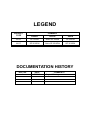
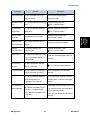
LEGEND
COMPANY
PRODUCT
CODE
LANIER
RICOH
SAVIN
M116
SP 3500N
Aficio SP 3500N
SP 3500N
M117
SP 3510DN
Aficio SP 3510DN
SP 3510DN
DOCUMENTATION HISTORY
REV. NO.
*
DATE
05/2012
COMMENTS
Original Printing
M116/M117
TABLE OF CONTENTS
1. PRODUCT INFORMATION ........................................................... 1-1
1.1 SPECIFICATIONS ..................................................................................... 1-1
1.2 MACHINE OVERVIEW .............................................................................. 1-2
1.2.1 COMPONENT LAYOUT ................................................................... 1-2
1.2.2 PAPER PATH ................................................................................... 1-3
1.2.3 DRIVE LAYOUT ............................................................................... 1-3
1.3 MACHINE CONFIGURATION ................................................................... 1-4
2. INSTALLATION ............................................................................. 2-1
2.1 INSTALLATION REQUIREMENTS ............................................................ 2-1
2.1.1 ENVIRONMENT ............................................................................... 2-1
2.1.2 MACHINE LEVEL ............................................................................. 2-2
2.1.3 MACHINE SPACE REQUIREMENT ................................................. 2-2
2.1.4 POWER REQUIREMENTS .............................................................. 2-3
2.1.5 INSTALLATION PROCEDURE ........................................................ 2-3
3. PREVENTIVE MAINTENANCE..................................................... 3-1
3.1 PM INTERVALS ......................................................................................... 3-1
3.1.1 PM PARTS ....................................................................................... 3-1
3.1.2 YIELD COUNTER ............................................................................. 3-1
Counter Reset ...................................................................................... 3-2
4. REPLACEMENT AND ADJUSTMENT ......................................... 4-1
4.1 BEFORE YOU START ............................................................................... 4-1
4.2 SPECIAL TOOLS ....................................................................................... 4-1
4.3 EXTERIOR COVERS ................................................................................ 4-2
4.3.1 FRONT COVER ................................................................................ 4-2
4.3.2 LEFT COVER ................................................................................... 4-4
4.3.3 REAR COVER .................................................................................. 4-6
4.3.4 RIGHT COVER ................................................................................. 4-7
4.3.5 TOP COVER ..................................................................................... 4-8
When installing the top cover ............................................................... 4-8
4.3.6 OPERATION PANEL ........................................................................ 4-9
SM
1
M116/M117
4.4 LASER UNIT ............................................................................................ 4-10
4.4.1 CAUTION DECAL LOCATIONS ..................................................... 4-10
4.4.2 LASER UNIT ................................................................................... 4-11
4.4.3 POLYGON MIRROR MOTOR ........................................................ 4-12
4.5 PAPER FEED AND EXIT ......................................................................... 4-13
4.5.1 PAPER FEED ROLLER .................................................................. 4-13
After installing a new paper feed roller ............................................... 4-13
4.5.2 FRICTION PAD .............................................................................. 4-14
4.5.3 PAPER END SENSOR ................................................................... 4-14
4.5.4 BY-PASS FEED ROLLER .............................................................. 4-15
4.5.5 BY-PASS FEED ROLLER FRICTION PAD .................................... 4-16
4.5.6 BY-PASS FEED SENSOR .............................................................. 4-17
4.5.7 PAPER FEED CLUTCH.................................................................. 4-17
4.5.8 RELAY CLUTCH ............................................................................ 4-18
4.5.9 REGISTRATION CLUTCH ............................................................. 4-19
4.5.10
TONER END SENSOR ............................................................ 4-19
4.5.11
PAPER EXIT SENSOR ............................................................ 4-20
4.5.12
RELAY SENSOR ..................................................................... 4-20
4.5.13
INVERTER SENSOR ............................................................... 4-20
4.5.14
REGISTRATION ROLLER AND SENSOR .............................. 4-21
4.6 PAPER TRANSFER ................................................................................ 4-24
4.6.1 TRANSFER ROLLER ..................................................................... 4-24
After installing a new transfer roller .................................................... 4-24
4.7 FUSING ................................................................................................... 4-25
4.7.1 FUSING UNIT ................................................................................. 4-25
Reinstallation...................................................................................... 4-27
After installing a new fusing unit ......................................................... 4-27
4.7.2 THERMOSTAT ............................................................................... 4-28
4.7.3 THERMISTOR ................................................................................ 4-29
4.7.4 FUSING LAMP ............................................................................... 4-30
When reinstall the fusing lamp ........................................................... 4-31
4.7.5 HOT ROLLER ................................................................................. 4-32
4.7.6 PRESSURE ROLLER ..................................................................... 4-33
4.7.7 HOT ROLLER STRIPPER PAWLS................................................. 4-33
4.8 MOTORS ................................................................................................. 4-34
4.8.1 MAIN MOTOR ................................................................................ 4-34
4.8.2 DUPLEX MOTOR (FOR M117) ...................................................... 4-34
4.9 ELECTRICAL COMPONENTS ................................................................ 4-35
M116/M117
2
SM
4.9.1 LAYOUT OF PC BOARDS ............................................................. 4-35
ECB (Engine Controller Board) .......................................................... 4-36
EEPROM............................................................................................ 4-37
Controller Board ................................................................................. 4-38
4.9.2 PSU ................................................................................................ 4-38
4.9.3 CHARGE TERMINAL CASE ........................................................... 4-42
4.10 OTHERS ............................................................................................ 4-43
4.10.1
COOLING FAN ........................................................................ 4-43
4.10.2
QUENCHING LAMP ................................................................ 4-43
4.11 IMAGE ADJUSTMENT....................................................................... 4-45
4.11.1
REGISTRATION ADJUSTMENT ............................................. 4-45
User Adjustment ................................................................................. 4-45
Service Adjustment ............................................................................ 4-45
5. SYSTEM MAINTENANCE REFERENCE ..................................... 5-1
5.1 SERVICE PROGRAM MODE .................................................................... 5-1
5.1.1 OVERVIEW ...................................................................................... 5-1
5.1.2 ENTERING ENGINE MAINTENANCE MODE .................................. 5-1
5.1.3 SERVICE MODE MENU ................................................................... 5-1
Selecting an Item.................................................................................. 5-1
Going into the Next Level/ Returning to the Previous Level ................. 5-1
Exiting the Service Mode Menu............................................................ 5-1
Menu List.............................................................................................. 5-2
5.2 CONFIGURATION AND MAINTENANCE PAGE .................................... 5-12
5.2.1 OVERVIEW .................................................................................... 5-12
To Print the Configuration Page/ Maintenance Page ......................... 5-12
Other Types of Reports ...................................................................... 5-12
Total Counter ..................................................................................... 5-13
5.3 FIRMWARE UPDATING .......................................................................... 5-14
5.3.1 CHECKING THE MACHINE FIRMWARE VERSION ...................... 5-14
5.3.2 UPDATING THE CONTROLLER FIRMWARE ............................... 5-14
Procedure........................................................................................... 5-14
5.3.3 UPDATING THE ENGINE FIRMWARE .......................................... 5-16
Procedure........................................................................................... 5-16
5.3.4 UPDATING THE BOOT LOADER FIRMWARE .............................. 5-17
5.3.5 UPDATING FAILURE ..................................................................... 5-17
5.3.6 FW UPDATE TOOL MESSAGES ................................................... 5-18
FW Update Tool Messages: Information ............................................ 5-18
FW Update Tool Messages: Error ...................................................... 5-21
SM
3
M116/M117
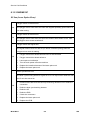
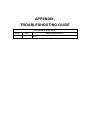
6. TROUBLESHOOTING................................................................... 6-1
6.1 SERVICE CALL CONDITIONS .................................................................. 6-1
6.1.1 SUMMARY ....................................................................................... 6-1
Fusing related SCs ............................................................................... 6-1
6.1.2 ENGINE SC ...................................................................................... 6-2
SC 2xx (Laser Optics Error) ................................................................. 6-2
SC 4xx (Image Transfer and Transfer Error) ........................................ 6-3
SC 5xx (Motor and Fusing Error).......................................................... 6-4
SC 6xx (Communication and Other Error)............................................ 6-8
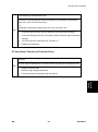
6.2 IMAGE PROBLEMS .................................................................................. 6-9
6.2.1 OVERVIEW ...................................................................................... 6-9
6.2.2 TEST PAGE PRINTING.................................................................. 6-10
Test Page Print Procedure ................................................................. 6-10
6.2.3 TEST PATTERN PRINTING ........................................................... 6-10
Test Pattern Print Procedure .............................................................. 6-10
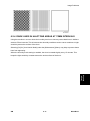
6.2.4 DARK LINES IN HALFTONE AREAS AT 75MM INTERVALS ....... 6-11
6.3 JAM .......................................................................................................... 6-12
6.3.1 JAM SENSOR LAYOUT ................................................................. 6-12
Paper Jam .......................................................................................... 6-12
6.3.2 JAM MESSAGE LIST ..................................................................... 6-13
Paper Jam .......................................................................................... 6-13
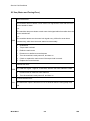
7. ENERGY SAVER ........................................................................... 7-1
7.1 ENERGY SAVER MODES......................................................................... 7-1
7.1.1 TIMER SETTINGS ............................................................................ 7-1
7.1.2 RETURN TO STAND-BY MODE ...................................................... 7-2
7.1.3 RECOMMENDATION ....................................................................... 7-2
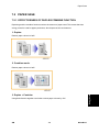
7.2 PAPER SAVE ............................................................................................ 7-3
7.2.1 EFFECTIVENESS OF DUPLEX/COMBINE FUNCTION .................. 7-3
1. Duplex: ............................................................................................. 7-3
2. Combine mode: ................................................................................ 7-3
3. Duplex + Combine:........................................................................... 7-3
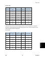
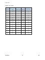
Total counter ........................................................................................ 7-4
M116/M117
4
SM
READ THIS FIRST
Safety Notices
Important Safety Notices
Prevention of Physical Injury
1.
Before disassembling or assembling parts of the machine and peripherals, make sure that the
machine power cord is unplugged.
2.
The wall outlet should be near the machine and easily accessible.
3.
If any adjustment or operation check has to be made with exterior covers off or open while the
main switch is turned on, keep hands away from electrified or mechanically driven
components.
4.
The machine drives some of its components when it completes the warm-up period. Be
careful to keep hands away from the mechanical and electrical components as the machine
starts operation.
5.
The inside and the metal parts of the fusing unit become extremely hot while the machine is
operating. Be careful to avoid touching those components with your bare hands.
Health Safety Conditions
Toner is non-toxic, but if you get either of them in your eyes by accident, it may cause temporary
eye discomfort. Try to remove with eye drops or flush with water as first aid. If unsuccessful, get
medical attention.
Observance of Electrical Safety Standards
The machine and its peripherals must be serviced by a customer service representative who has
completed the training course on those models.
Safety and Ecological Notes for Disposal
1.
Do not incinerate toner bottles or used toner. Toner dust may ignite suddenly when exposed
to an open flame.
2.
Dispose of used toner, the maintenance unit which includes developer or the organic
photoconductor in accordance with local regulations. (These are non-toxic supplies.)
3.
Dispose of replaced parts in accordance with local regulations.
To prevent a fire or explosion, keep the machine away from flammable liquids, gases,
and aerosols. A fire or an explosion might occur.
Handling Toner
Work carefully when removing paper jams or replacing toner bottles or cartridges to avoid
spilling toner on clothing or the hands.
If toner is inhaled, immediately gargle with large amounts of cold water and move to a well
ventilated location. If there are signs of irritation or other problems, seek medical attention.
If toner gets on the skin, wash immediately with soap and cold running water.
If toner gets into the eyes, flush the eyes with cold running water or eye wash. If there are
signs of irritation or other problems, seek medical attention.
If toner is swallowed, drink a large amount of cold water to dilute the ingested toner. If there
are signs of any problem, seek medical attention.
If toner spills on clothing, wash the affected area immediately with soap and cold water. Never
use hot water! Hot water can cause toner to set and permanently stain fabric.
Always store toner and developer supplies such as toner and developer packages, cartridges,
and bottles (including used toner and empty bottles and cartridges) out of the reach of
children.
Always store fresh toner supplies or empty bottles or cartridges in a cool, dry location that is
not exposed to direct sunlight.
Do not use the cleaner to suck spilled toner (including used toner). Sucked toner may
cause firing or explosion due to electrical contact flickering inside the cleaner. However, it
is possible to use the cleaner designed for dust explosion-proof purpose. If toner is
spilled over the floor, sweep up spilled toner slowly and clean remainder with wet cloth.
M116/M117
6
SM
Laser Safety
The Center for Devices and Radiological Health (CDRH) prohibits the repair of laser-based optical
units in the field. The optical housing unit can only be repaired in a factory or at a location with the
requisite equipment. The laser subsystem is replaceable in the field by a qualified Customer
Engineer. The laser chassis is not repairable in the field. Customer engineers are therefore
directed to return all chassis and laser subsystems to the factory or service depot when
replacement of the optical subsystem is required.
Use of controls, or adjustment, or performance of procedures other than those specified
in this manual may result in hazardous radiation exposure.
Turn off the main switch before attempting any of the procedures in the Laser Optics
Housing Unit section. Laser beams can seriously damage your eyes.
CAUTION MARKING:
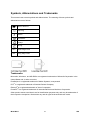
Symbols, Abbreviations and Trademarks
This manual uses several symbols and abbreviations. The meaning of those symbols and
abbreviations are as follows:
See or Refer to
Clip ring
Screw
Connector
Clamp
E-ring
SEF
Short Edge Feed
LEF
Long Edge Feed
Trademarks
Microsoft®, Windows®, and MS-DOS® are registered trademarks of Microsoft Corporation in the
United States and /or other countries.
PostScript® is a registered trademark of Adobe Systems, Incorporated.
PCL® is a registered trademark of Hewlett-Packard Company.
Ethernet® is a registered trademark of Xerox Corporation.
PowerPC® is a registered trademark of International Business Machines Corporation.
Other product names used herein are for identification purposes only and may be trademarks of
their respective companies. We disclaim any and all rights involved with those marks.
M116/M117
8
SM
PRODUCT INFORMATION
R E V I S I O N H I S T O RY
Pag e
Date
Ad d ed / Upd ated / New
None
Specifications
Product
Information
1. PRODUCT INFORMATION
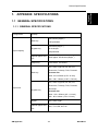
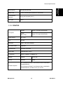
1.1 SPECIFICATIONS
See "Appendices" for the following information:
"General Specifications"
"Printer"
"Supported Paper Sizes"
SM
1-1
M116/M117
Machine Overview
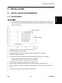
1.2 MACHINE OVERVIEW
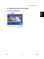
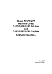
1.2.1 COMPONENT LAYOUT
1.
Laser unit
9.
Friction pad
2.
Quenching lamp
10.
Transfer roller
3.
Cartridge (AIO-type)
11.
Paper Tray
4.
Development roller
12.
Fusing Unit
5.
Registration roller
13.
Pressure Roller
6.
By-pass feed roller
14.
Paper exit roller
7.
By-pass feed tray
15.
Hot Roller
8.
Paper feed roller
16.
Drum
M116/M117
1-2
SM
Machine Overview
Product
Information
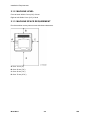
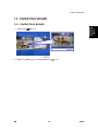
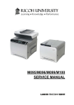
1.2.2 PAPER PATH
[A] Duplex section (For M117)
[B] Standard paper tray unit
[C] Optional paper tray unit
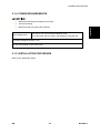
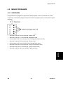
1.2.3 DRIVE LAYOUT
1. Duplex Motor
2. Main Motor
3. Registration Clutch
SM
4. Relay Clutch
5. Paper Feed Clutch
1-3
M116/M117
Machine Configuration
1.3 MACHINE CONFIGURATION
Models
Optional
Duplex
Optional
Unit
Memory
NA
NA
250x1
Yes
Auto
NA
250x1
Yes
RN-P2a
(M116)
RN-P2b
(M117)
Tray
PCL PS
(M355)
NA: Not Available
M116/M117
1-4
SM
INSTALLATION
R E V I S I O N H I S T O RY
Pag e
Date
Ad d ed / Upd ated / New
None
Installation Requirements
2. INSTALLATION
2.1.1 ENVIRONMENT
This machine, which uses high voltage power sources, can generate ozone gas. High
ozone density is harmful to human health. Therefore, the machine must be installed in a
well-ventilated room.
1.
Temperature Rage: 10°C to 32°C (50°F to 89.6°F)
2.
Humidity Range: 15% to 80% RH
3.
Ambient Illumination: Less than 2,000 lux (do not expose to direct sunlight)
4.
Ventilation: 3 times/hr/person
5.
Do not put the machine in areas with sudden temperature changes. This includes:
Areas directly exposed to cool air from air conditioning
Areas directly exposed to heat from a heating system.
6.
Do not put the machine in areas exposed to corrosive gas.
7.
Do not install the machine at locations over 2,000 m (6,562 ft.) above sea level.
8.
Put the machine on a strong, level base. (Tilting towards any side must be no more than 3
mm.)
9.
SM
Do not put the machine in areas with strong vibrations.
2-1
M116/M117
Installation
2.1 INSTALLATION REQUIREMENTS
Installation Requirements
2.1.2 MACHINE LEVEL
Front to back: Within 5 mm (0.2") of level
Right to left: Within 5 mm (0.2") of level
2.1.3 MACHINE SPACE REQUIREMENT
Put the machine near a power source with these clearances:
A: Over 10 cm (4")
B: Over 20 cm (7.9")
C: Over 20 cm (7.9")
D: Over 70 cm (27.6")
M116/M117
2-2
SM
Installation Requirements
Make sure that the plug is tightly in the outlet.
Avoid multi-wiring.
Make sure that you ground the machine.
Input voltage level
Installation
2.1.4 POWER REQUIREMENTS
NA: 120 V, TW: 110 V, 60 Hz: Less than 10 A
EU/ Asia/ CHN: 220 V to 240 V, 50 Hz/60 Hz: Less than 5 A
Permitted voltage fluctuation: 10%
Do not set anything on the power cord.
2.1.5 INSTALLATION PROCEDURE
Refer to the "Hardware Guide".
SM
2-3
M116/M117
PREVENTIVE MAINTENANCE
R E V I S I O N H I S T O RY
Pag e
Date
Ad d ed / Upd ated / New
None
PM Intervals
3. PREVENTIVE MAINTENANCE
3.1 PM INTERVALS
3.1.1 PM PARTS
There are no PM parts in this machine.
Other than the three Yield Parts listed below, there are essentially no PM parts required
for this product.
These three items will need to be replaced in cases where their yield is near, however,
given the APV (Average Printer Volume) for this product, these "yield parts*1 " are
expected to outlast the working life of the machine.
*1 "Yield Parts": Parts whose expected yield is longer than the machine lifetime when taking into
consideration the machine's APV.
Description
Expected Yield
Q'ty/unit
Paper Feed Roller
120 K prints
1
Transfer Roller
120 K prints
1
Fusing Unit
120 K prints
1
3.1.2 YIELD COUNTER
Yield counters for each yield part can be checked by the following methods.
Configuration Page in the “List/Test Print” menu
Web Image Monitor
SM
3-1
M116/M117
Preventive
Maintenance
PM Intervals
The machine displays "Fuser life end notice", "Transfer roller life end notice" or "Life End
of Paper Feed Roller Unit" when one of these counters reaches each yield.
Counter Reset
The process below shows how to reset the yield counters.
1.
Enter the "Service Mode".
2.
Select "Eng Maintenance", and then press "OK" key.
3.
Select "Reset FuserUnit", "Reset Trans Rol" or "Reset Feed " and then press "OK" key.
4.
Select “Execute” and the press “OK” key.
5.
Exit the Service Mode".
M116/M117
3-2
SM
REPLACEMENT AND ADJUSTMENT
R E V I S I O N H I S T O RY
Pag e
Date
Ad d ed / Upd ated / New
None
Before You Start
4. REPLACEMENT AND ADJUSTMENT
4.1 BEFORE YOU START
If there are printer jobs in the machine, print out all jobs in the printer buffer.
Turn off the main power switch and unplug the machine before you do the procedures in
this section.
PC: Windows XP/Vista/7, Windows Server 2003/2003 R2, 2008/2008 R2
USB or network cable
SM
Replacement
and
Adjustment
4.2 SPECIAL TOOLS
A computer is necessary to update the firmware.
4-1
M116/M117
Exterior Covers
4.3 EXTERIOR COVERS
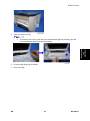
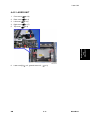
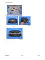
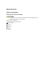
4.3.1 FRONT COVER
1.
Pull out the standard paper tray [A].
2.
Remove two tabs [A].
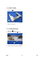
3.
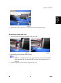
On the right side, down the tab, and then slide the bypass tray [A] to the right.
4.
Pull out the bypass tray [A].
M116/M117
4-2
SM
Exterior Covers
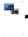
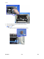
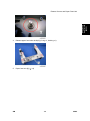
5.
Open the front cover [A].
To open the front cover, push the cover release button [B] and (carefully) pull the
Replacement
and
Adjustment
cover forward and open (it hinges downward).
6.
Push the right hinge [A] to release.
7.
Front cover [B]
SM
4-3
M116/M117
Exterior Covers
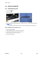
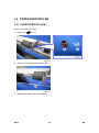
4.3.2 LEFT COVER
1.
Front cover (
p.4-2)
2.
Rear cover (
p.4-6)
3.
Remove two screws [A] on the front side of the left cover.
4.
Remove a screw [A] on the rear upper side of the left cover.
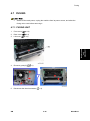
5.
Pull the rear upper part [A] of the left cover to release the hooks.
M116/M117
Located outside of the cover has marks indicating the position of the hook.
4-4
SM
Exterior Covers
6.
Pull the front upper part [A] of the left cover to release the hooks.
Located outside of the cover has marks indicating the position of the hook.
Replacement
and
Adjustment
7.
Pull the front bottom part of the left cover [A] to release the hooks.
8.
Remove the Left cover [A].
SM
Located outside of the cover has marks indicating the position of the hook.
Located outside of the cover has marks indicating the position of the hook.
4-5
M116/M117
Exterior Covers
There are many hooks and tabs inside the left cover. Before removing the left cover,
see the images below.
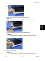
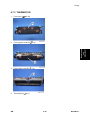
4.3.3 REAR COVER
1.
Open the rear cover [A]
2.
Slide the shaft [B] in the direction of the blue arrow, and remove the rear cover [A].
M116/M117
4-6
SM
Exterior Covers
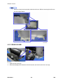
4.3.4 RIGHT COVER
1.
Front cover (
p.4-2)
2.
Rear cover (
p.4-6)
3.
Right cover [A] (
Located outside of the cover has marks indicating the position of the hook.
There are many hooks and tabs inside the right cover. Before removing the right
cover, see the images below.
SM
4-7
M116/M117
Replacement
and
Adjustment
x 3, hook at arrow mark)
Exterior Covers
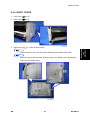
4.3.5 TOP COVER
1.
Front cover (
p.4-2)
2.
Rear cover (
p.4-6)
3.
Left cover (
4.
Right cover (
5.
Top cover [A] (
p.4-4)
p.4-7)
x 2,
x 1, hook x 5)
When installing the top cover
When re-installing the top cover, always verify that the two paperweights [A] are lifted. If they
are not lifted to fit into the paper slot, the paperweights [A] could be damaged.
Make sure that these paperweights [A] can be moved smoothly (up and down) after installing
the top cover. If these paperweights do not move smoothly, try installing the top cover again.
M116/M117
4-8
SM
Exterior Covers
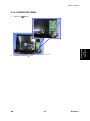
4.3.6 OPERATION PANEL
Top cover (
2.
Operation panel [A] (
SM
p.4-8)
Replacement
and
Adjustment
1.
x 2)
4-9
M116/M117
Laser Unit
4.4 LASER UNIT
Turn off the main power switch and unplug the machine before attempting any of the
procedures in this section. Laser beams can seriously damage your eyes.
4.4.1 CAUTION DECAL LOCATIONS
Caution decal is attached as shown below.
Be sure to turn off the main switch and disconnect the power plug from the power outlet
before beginning any disassembly or adjustment of the laser unit. This machine uses a
class IIIB laser beam with a wavelength of 648 to 663 nm and an output of 9 mW. The
laser can cause serious eye injury.
M116/M117
4-10
SM
Laser Unit
4.4.2 LASER UNIT
1.
Front cover (
p.4-2)
2.
Rear cover (
p.4-6)
3.
Left cover (
4.
Right cover (
5.
Top cover (
6.
Laser unit [A] (
p.4-4)
p.4-7)
Replacement
and
Adjustment
p.4-8)
SM
x 3, ground screw x 3,
x 2)
4-11
M116/M117
Laser Unit
4.4.3 POLYGON MIRROR MOTOR
Turn off the main switch and unplug the machine before attempting any of the procedures
in this section. Laser beams can seriously damage your eyes.
p.4-11)
1.
Laser unit (
2.
Polygon mirror cover [A] (
x 2)
3.
Polygon mirror motor [A] (
x 4,
M116/M117
x 1)
Never touch the surface of the mirror with bare hands.
4-12
SM
Paper Feed and Exit
4.5 PAPER FEED AND EXIT
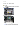
1.
Pull out the standard paper tray.
2.
Remove the AIO.
3.
Set the machine with the rear side facing down, resting on the table.
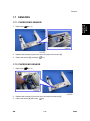
4.
Slide the paper feed shaft [A] to the left side (
5.
Slide the paper feed roller [B] to right side, and remove it (hook).
Replacement
and
Adjustment
4.5.1 PAPER FEED ROLLER
x 2).
After installing a new paper feed roller
1.
Enter the "Service Mode".
2.
Select "Eng Maintenance", and then press "OK" key.
3.
Select "Reset Feed" and then press "OK" key.
4.
Select “Execute” and the press “OK” key.
5.
Exit the Service Mode".
SM
4-13
M116/M117
Paper Feed and Exit
4.5.2 FRICTION PAD
1.
Remove the paper tray unit from the machine before removing the friction pad.
2.
Friction pad [A] (2 hooks, 1 spring)
When reinstalling the friction pad follow this order:
1.
Replace the spring.
2.
Insert the right side of the friction pad first, followed by the left side.
3.
Gently push the friction pad down into the slot and then pull forward very slightly.
4.5.3 PAPER END SENSOR
1.
Set the machine with the rear side facing down, resting on the table.
2.
Paper end sensor [A] (hooks,
M116/M117
x 1)
4-14
SM
Paper Feed and Exit
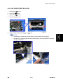
4.5.4 BY-PASS FEED ROLLER
1.
Front cover (
p.4-2)
2.
Left cover (
3.
Right cover (
4.
Pull out the paper tray.
5.
By-pass lower guide plate [A] (
p.4-4)
p.4-7)
x 2)
Reinstall the by-pass lower guide plate [A] while pressing the spring [B].
Be careful for the spring [B] and the ground plate [C] not to fall inside the machine
during reinstallation.
SM
4-15
M116/M117
Replacement
and
Adjustment
x 4,
Paper Feed and Exit
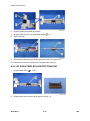
6.
By-pass upper guide plate [A] (hooks)
7.
By-pass solenoid cover, by-pass solenoid [B] (
8.
Gear [C] (hook)
9.
Slide the by-pass feed roller shaft [A] to the left side, and remove it.
x 1)
10. Remove the metal cover [B] from the by-pass feed roller [C].
4.5.5 BY-PASS FEED ROLLER FRICTION PAD
1.
By-pass feed roller (
2.
By-pass feed roller friction pad [A] (hooks, spring x 1)
M116/M117
p.4-15)
4-16
SM
Paper Feed and Exit
4.5.6 BY-PASS FEED SENSOR
1.
Front cover (
p.4-2)
2.
Right cover (
p.4-7)
3.
By-pass feed sensor [A] (hooks,
x 1)
1.
Top cover (
2.
ECB (
3.
Controller board (
4.
Release all harnesses [A] from the clamps.
5.
Harness guide plate [B] (
6.
Drive unit [A] (
SM
Replacement
and
Adjustment
4.5.7 PAPER FEED CLUTCH
p.4-2)
p.4-36 "ECB (Engine Controller Board)")
x 5,
p.4-38)
x 2)
x 1,
x 2, timing belt)
4-17
M116/M117
Paper Feed and Exit
7.
Paper feed clutch [A] (
x 1,
x 1)
4.5.8 RELAY CLUTCH
1.
Drive unit (
2.
Relay clutch [A] (
M116/M117
p.4-17 "Paper Feed Clutch")
x 1)
4-18
SM
Paper Feed and Exit
4.5.9 REGISTRATION CLUTCH
1.
Drive unit (
p.4-17 "Paper Feed Clutch")
2.
Registration clutch [A] (
x 1)
1.
Drive unit (
2.
Reflective sensor with bracket [A] (
3.
Reflective sensor [B]
SM
Replacement
and
Adjustment
4.5.10 TONER END SENSOR
p.4-17 "Paper Feed Clutch")
x 1)
4-19
M116/M117
Paper Feed and Exit
4.5.11 PAPER EXIT SENSOR
1.
Rear cover (
p.4-6)
2.
Paper exit sensor [A] (
x 1, hooks)
4.5.12 RELAY SENSOR
1.
Rear cover (
p.4-6)
2.
Relay sensor [A] (
x 1, hooks)
4.5.13 INVERTER SENSOR
1.
Duplex transport guide (
2.
Inverter sensor [A] (
M116/M117
p.4-38 "PSU")
x 1, hooks)
4-20
SM
Paper Feed and Exit
4.5.14 REGISTRATION ROLLER AND SENSOR
1.
Pull out the paper tray.
2.
PSU (
3.
Paper feed clutch (
4.
Relay clutch (
5.
Registration clutch (
6.
Heat insulating plate [A] (
7.
Exit roller base [B] (
8.
Imaging unit base [A] (
9.
Remove the four screws in the right frame [A].
SM
p.4-38)
p.4-17)
p.4-18)
Replacement
and
Adjustment
p.4-19)
x 2)
x 2)
x 4)
4-21
M116/M117
Paper Feed and Exit
10. Remove the four screws in the left frame [A].
11. Registration unit [A]
12. Upper guide plate [B]
13. Registration roller [A]
M116/M117
4-22
SM
Paper Feed and Exit
SM
Replacement
and
Adjustment
14. Registration sensor [A]
4-23
M116/M117
Paper Transfer
4.6 PAPER TRANSFER
4.6.1 TRANSFER ROLLER
1.
Front cover (
2.
Remove the AIO.
3.
Remove the transfer roller [A] (Bushing x 2, spring x 2, gear x 1, collar x 1) as shown above.
p.4-2)
Do not touch the transfer roller surface, when reinstalling the new transfer roller.
After installing a new transfer roller
1.
Enter the "Service Mode".
2.
Select "Eng Maintenance", and then press "OK" key.
3.
Select "Reset Trans Rol" and then press "OK" key.
4.
Select “Execute” and the press “OK” key.
5.
Exit the Service Mode".
M116/M117
4-24
SM
Fusing
4.7 FUSING
Switch off the main power, unplug the machine from its power source, and allow the
fusing unit to cool before removing it.
4.7.1 FUSING UNIT
1.
Front cover (
p.4-2)
2.
Rear cover (
p.4-6)
3.
Left cover (
4.
Entrance guide [A] (
5.
Disconnect the three harnesses (
Replacement
and
Adjustment
p.4-4)
SM
x 1)
x 2)
4-25
M116/M117
Fusing
6.
Pass the cable [A] through the hole [B] inside the machine.
7.
Fusing unit [C] (
M116/M117
x 4)
Make sure that the two bushings [A] remain be setting.
4-26
SM
Fusing
Reinstallation
Pass the cable [A] of fusing unit through the hole [B] outside, after setting the fusing unit.
1.
Enter the "Service Mode".
2.
Select "Eng Maintenance", and then press "OK" key.
3.
Select "Reset FuserUnit" and then press "OK" key.
4.
Select “Execute” and the press “OK” key.
5.
Exit the Service Mode".
SM
4-27
Replacement
and
Adjustment
After installing a new fusing unit
M116/M117
Fusing
4.7.2 THERMOSTAT
Do not recycle a thermoswitch that is already opened. Safety is not guaranteed if you do
this.
p.4-25)
1.
Fusing unit (
2.
Fusing upper cover [A] (
3.
Thermostat [A] (
M116/M117
x 4)
x 2)
4-28
SM
Fusing
4.7.3 THERMISTOR
Fusing unit (
p.4-25)
2.
Fusing upper cover [A] (
3.
Fusing front cover [A] (
4.
Thermistor [A] (
x 4)
Replacement
and
Adjustment
1.
SM
x 2)
x 1)
4-29
M116/M117
Fusing
4.7.4 FUSING LAMP
1.
Fusing Unit (
2.
Fusing side covers [A] (
3.
Ground-wires (
4.
Fusing lamp [A]
M116/M117
p.4-25)
x 2 each)
x 1 each)
4-30
SM
Fusing
When reinstall the fusing lamp
Replacement
and
Adjustment
The flat terminal [A] must be placed on the right side of the fusing unit (fusing cable side).
SM
4-31
M116/M117
Fusing
4.7.5 HOT ROLLER
1.
Fusing lamp (
2.
Brackets [A] (
3.
Ground Plate [A] (
4.
Hot roller [A] (C-ring x 2, gear x 1, bushing x 2)
M116/M117
p.4-30)
x 2)
x 1)
4-32
SM
Fusing
4.7.6 PRESSURE ROLLER
1.
Hot roller (
p.4-32)
2.
Pressure roller [A] (Bearing x 2)
4.7.7 HOT ROLLER STRIPPER PAWLS
1.
Fusing unit (
p.4-25)
2.
Fusing upper cover (
3.
Metal holders [A] (1 holder for each pawl:
4.
Hot roller stripper pawls [A] (1 spring for each pawl)
Replacement
and
Adjustment
p.4-28 "Thermostat")
SM
x 2 each)
4-33
M116/M117
Motors
4.8 MOTORS
4.8.1 MAIN MOTOR
1.
Front cover (
p.4-2)
2.
Left cover (
3.
Harness guide [A] (
4.
Main motor [B] (
p.4-4)
x 2)
x 4,
x 1)
4.8.2 DUPLEX MOTOR (FOR M117)
1.
Front cover (
p.4-2)
2.
Rear cover (
p.4-6)
3.
Left cover (
4.
Right cover (
5.
Top cover (
6.
Duplex motor [A] (
M116/M117
p.4-4)
p.4-7)
p.4-8)
x 2,
x 1)
4-34
SM
Electrical Components
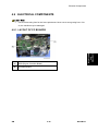
4.9 ELECTRICAL COMPONENTS
Use a correct rating fuse for the fuse replacement. Never use a wrong rating fuse. If do
so, the machine may be damaged.
[A]
ECB (Engine Controller Board)
[B]
Controller Board
SM
Replacement
and
Adjustment
4.9.1 LAYOUT OF PC BOARDS
4-35
M116/M117
Electrical Components
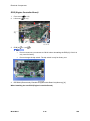
ECB (Engine Controller Board)
1.
Front cover (
2.
Left cover (
3.
ECB [A] (
p.4-2)
p.4-4)
x 4, all
s)
Do not connect any connectors to CN181 when reinstalling the ECB [A]. CN181 is
only used for factory.
4.
Do not change the dip switch. The dip switch is only for factory use.
EEPROM (Electronically Erasable Programmable Read Only Memory) [A]
When installing the new ECB (Engine Controller Board)
M116/M117
4-36
SM
1.
Remove the EEPROM from the old ECB.
2.
Install it on the new ECB after replacing the ECB.
3.
Replace the EEPROM if the EEPROM on the old ECB is defective.
Keep the EEPROM away from any objects that can cause static electricity. Static
electricity can damage EEPROM data.
Make sure that the EEPROM is correctly installed on the ECB.
EEPROM
Replacement procedures for the new EEPROM are included in the "ECB (Engine Controller
Board)" replacement procedure. Refer to "ECB (Engine Controller Board)" for details.
Do the following settings after installing a "new" EEPROM.
-Input the PnP Name, Destination in Service Mode.
-Adjust the Registration in Service Mode.
-Input serial number on the serial number input display after installing the new EEPROM
SM
Ask your supervisor about how to access the serial number input display.
4-37
M116/M117
Replacement
and
Adjustment
Electrical Components
Electrical Components
Controller Board
1.
ECB (
p.4-36 "ECB (Engine Controller Board)")
2.
Controller board [A] (
x 4,
x 1)
4.9.2 PSU
1.
Pull out the standard paper tray.
2.
Front cover (
p.4-2)
3.
Rear cover (
p.4-6)
4.
Left cover (
5.
Right cover (
6.
Top cover (
7.
ECB (
8.
Drive unit (
9.
Disconnect three connectors in left frame(
p.4-7)
p.4-8)
p.4-36 "ECB (Engine Controller Board)")
10. Bracket [A] (
M116/M117
p.4-4)
p.4-17 "Paper Feed Clutch")
x 1)
x 2)
4-38
SM
Electrical Components
11. Main power switch bracket [A] in right frame(
x 2)
12. Remove the main power cord [B] as sown above(
x 2).
Replacement
and
Adjustment
13. Remove the ground wire and two connectors.
14. Rear low cover [A] (
x 3)
15. Release the lock [A], and then remove the entrance guide [B] (
16. Fusing Unit(
SM
x 1).
p.4-25)
4-39
M116/M117
Electrical Components
17. For M117 only: Duplex transport guide [A] (
x 2)
18. For M117 only: Set the machine with the front side facing down, resting on the table.
19. For M117 only: Release the link [A] (
20. For M117 only: Duplex cover [A] (
M116/M117
x 1)
x 4,
x 1, gear x 1)
4-40
SM
21. PSU [A] (
SM
x 4,
Replacement
and
Adjustment
Electrical Components
x 1)
4-41
M116/M117
Electrical Components
4.9.3 CHARGE TERMINAL CASE
1.
Right cover (
2.
Charge terminal case [A] with the harness (
3.
Remove the harness [A] (
4.
Remove the four springs and terminal pins [B].
5.
Charge terminal case [C]
M116/M117
p.4-7)
x 2,
x 1, hooks)
x 4).
4-42
SM
Others
4.10 OTHERS
4.10.1 COOLING FAN
Right cover (
2.
Cooling fan [A] (
p.4-7)
x 2,
x 1)
Install the Cooling fan [A] with its decal facing the outside of the machine.
4.10.2 QUENCHING LAMP
1.
Top Cover (
2.
Release two hooks of the quenching lamp with the case [A], and remove it.
SM
p.4-8)
4-43
M116/M117
Replacement
and
Adjustment
1.
Others
3.
Remove the quenching lamp [A] from the case (hook x 3).
M116/M117
4-44
SM
Image Adjustment
4.11 IMAGE ADJUSTMENT
4.11.1 REGISTRATION ADJUSTMENT
User Adjustment
The paper registration can also be adjusted with the user mode ("Menu"). For details, see the
"Software Guide".
Service Adjustment
1.
Print the test pattern (
p.6-10).
Print out the test pattern before changing the paper registration setting.
Enter the "Service Mode".
3.
Select "Eng. Maintenance", and then press "OK" key.
4.
Select the "Registration", and then press "OK" key.
Replacement
and
Adjustment
2.
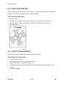
(1): Feed Direction
(2): Vertical Adjustment
(3): Horizontal Adjustment
(4): Print Area
5.
Press the "Up" or "Down" keys to set the registration value from -15 to +15 (that is, from -1.5
to +1.5 mm, in 0.1 mm increments).
6.
SM
Increase the value to shift the print area in the plus direction.
Decrease to shift in the minus direction.
Adjust the margins of the test page so that they are equal in size.
4-45
M116/M117
SYSTEM MAINTENANCE REFERENCE
R E V I S I O N H I S T O RY
Pag e
Date
Ad d ed / Upd ated / New
None
Service Program Mode
5. SYSTEM MAINTENANCE REFERENCE
5.1 SERVICE PROGRAM MODE
5.1.1 OVERVIEW
This model has several service menus. Each service menu has several adjustment items. This
section explains how to enter each service menu and what you can do in each service menu.
5.1.2 ENTERING ENGINE MAINTENANCE MODE
While holding the <Stop/Start Key> and <Escape Key> at the same time, turn on the Main Power
Switch to the “ON” position.
Note: There is no SOM (Smart Organizing Monitor) utility.
5.1.3 SERVICE MODE MENU
System
Maintenance
Reference
Selecting an Item
To select an item, press the "Up" or "Down" key.
Going into the Next Level/ Returning to the Previous Level
To go into the next level of an item, select an item then press the "OK" key.
To return to the previous level of an item, press the "Escape" key.
Exiting the Service Mode Menu
To exit the Service Mode menu, select the "End", and then press “OK” key.
SM
5-1
M116/M117
Service Program Mode
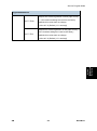
Menu List
Display Info
Displays the Model Name, Depends on Engine
Model Name
FW Ver.
Firmware Settings
CTL FW Ver.
Displays the Firmware Version
Engine FW Ver.
Displays the Engine Firmware Version
PDL FW Ver.
Displays the PDL Firmware Version.
Total Page
Displays the total pages
JAM Page
Displays the jam total
Counter
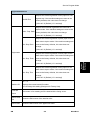
Engine Maintenance
Brand
Do not change this setting (Designed for Factory Use).
RICOH/ GESTETNER/ INFOTEC/ LANIEA/ NRG/ SAVIN/ SP
Sets the model name to a host via USB device.
PNP
Do not change this setting (Designed for Factory Use).
[0x00 – 0x7F]
Sets the destination and updates the engine setting.
Destination
Do not change this setting (Designed for Factory Use).
DOM/ NA/ EU (Default)/ ASIA/ CHN/ TAIWAN/ KOREA
Adjusts the horizontal registration for tray 1. If the
Horiz.: Tray 1
machine settings are reset to the factory defaults, this
value does not change.
[-40 to 40 / 0 (Default) / 0.1 mm/step]
Registration
Adjusts the vertical registration of plain paper for
Vert.T1.Plain
tray1. If the machine settings are reset to the factory
defaults, this value does not change.
[-40 to 40 / 0 (Default) / 0.1 mm/step]
M116/M117
5-2
SM
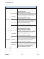
Service Program Mode
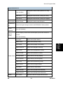
Engine Maintenance
Adjusts the vertical registration of thick paper for tray
Vert.T1.Thick
1. If the machine settings are reset to the factory
defaults, this value does not change.
[-40 to 40 / 0 (Default) / 0.1 mm/step]
Adjusts the vertical registration of thin paper for tray 1.
Vert.T1.Thin
If the machine settings are reset to the factory
defaults, this value does not change.
System
Maintenance
Reference
[-40 to 40 / 0 (Default) / 0.1 mm/step]
SM
5-3
M116/M117
Service Program Mode
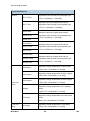
Engine Maintenance
Adjusts the horizontal registration for tray 1. If the
Horiz.: Tray 2
machine settings are reset to the factory defaults, this
value does not change.
[-40 to 40 / 0 (Default) / 0.1 mm/step]
Adjusts the vertical registration of plain paper for tray
Vert.T2.Plain
2. If the machine settings are reset to the factory
defaults, this value does not change.
[-40 to 40 / 0 (Default) / 0.1 mm/step]
Registration
Adjusts the vertical registration of thick paper for tray
Vert.T2.Thick
2. If the machine settings are reset to the factory
defaults, this value does not change.
[-40 to 40 / 0 (Default) / 0.1 mm/step]
Adjusts the vertical registration of thin paper for tray 2.
Vert.T2.Thin
If the machine settings are reset to the factory
defaults, this value does not change.
[-40 to 40 / 0 (Default) / 0.1 mm/step]
Adjusts the horizontal registration for the bypass tray.
Horiz.: Bypass
If the machine settings are reset to the factory
defaults, this value does not change.
[-40 to 40 / 0 (Default) / 0.1 mm/step]
Adjusts the vertical registration of plain paper for the
Registration
Vert.BP.Plain
bypass tray. If the machine settings are reset to the
factory defaults, this value does not change.
[-40 to 40 / 0 (Default) / 0.1 mm/step]
Adjusts the vertical registration of thick paper for the
Vert.BP.Thick
bypass tray. If the machine settings are reset to the
factory defaults, this value does not change.
[-40 to 40 / 0 (Default) / 0.1 mm/step]
M116/M117
5-4
SM
Service Program Mode
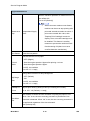
Engine Maintenance
Adjusts the vertical registration of thin paper for t the
Vert.BP.Thin
bypass tray. If the machine settings are reset to the
factory defaults, this value does not change.
[-40 to 40 / 0 (Default) / 0.1 mm/step]
Adjusts the horizontal registration the back side in
Horiz.: Dup. Back
duplex mode. If the machine settings are reset to the
factory defaults, this value does not change.
[-40 to 40 / 0 (Default) / 0.1 mm/step]
Adjusts the vertical registration of plain paper for the
back side in duplex mode. If the machine settings are
Vert. Dup. Plain
reset to the factory defaults, this value does not
change.
[-40 to 40 / 0 (Default) / 0.1 mm/step]
Registration
Adjusts the vertical registration of thick paper for the
back side in duplex mode. If the machine settings are
Vert. Dup. Thick
reset to the factory defaults, this value does not
[-40 to 40 / 0 (Default) / 0.1 mm/step]
Adjusts the vertical registration of thin paper for the
back side in duplex mode. If the machine settings are
Vert. Dup. Thin
reset to the factory defaults, this value does not
change.
[-40 to 40 / 0 (Default) / 0.1 mm/step]
00* – 7F
Machine ID
Displays the current brand ID number.
Do not change this setting (Designed for Factory Use).
Fuser SC
Reset
Reset Trans
Rol
Reset Feed
SM
This button is for resetting an SC related with the fusing errors.
Clears the EM counter of the transfer roller.
Clears the EM counter of the paper feed roller.
5-5
M116/M117
System
Maintenance
Reference
change.
Service Program Mode
Engine Maintenance
Reset
FuserUnit
Motor
Rotation
Clears the EM counter of the fusing unit.
Displays the main motor rotation time.
Kind ID
Toner End His
Print
Cartridge
Ref Flag State
U Print Counter
OPC Rotation.T
PreOPC Rota.T
OPC Life Info
Alert Status
PreAlert Status
Trans Rol Rem
Trans Rol Time
EM Counter Trans Rol Page
Info
Paper Rol Rem
Paper Rol Page
M116/M117
Displays the toner cartridge (AIO) information
(Kind ID).
Displays the toner cartridge (AIO) information
(Toner End History).
Displays the toner cartridge (AIO) information
(Refill flag status).
Displays the toner cartridge (AIO) information
(Unit Print Counter).
Displays the OPC life information (OPC rotation
time).
Displays the OPC life information (Pre-OPC
rotation time)
Displays the OPC life information (Alert status)
Displays the OPC life information (Pre-Alert
status)
Displays the total counter (Remain of Transfer
Roller).
Displays the EM counter (Transfer Roller: Time).
Displays the EM counter (Transfer Roller: pages).
Displays the total counter (Remain of Paper Feed
Roller).
Displays the EM counter (Paper Feed Roller:
pages).
5-6
SM
Service Program Mode
Engine Maintenance
Fuser Unit Rem
Displays the EM counter (Fusing Unit: time).
Fuser Unit P
Displays the EM counter (Fusing Unit: pages).
SC559
Detection
EM Life
Display
Displays the total counter (Engine).
Resets the engine settings stored in the EEPROM to factory default.
[On or Off (Default)]
Sets the display of alert when each EM parts yield of this machine is
reached.
[On or Off (Default)]
Main Motor
Output check (Main Motor)
Middle Clutch
Output check (Relay Clutch)
Tray1 Clutch
Output check (Paper Feed Clutch)
Bypass solenoid
Output check (Bypass solenoid)
Regist Clutch
Output check (Registration Clutch)
Reserve Clutch
Output check (Reserve Clutch)
Output check Fan High Speed
Output check (Fan High Speed)
Fan Low Speed
Output check (Fan Low Speed)
Erase Lamp
Output check (Quenching Lamp)
Polygon Motor
Output check (Polygon Motor)
Tray2 Motor
Output check (Tray2 Motor)
D Motor Normal
Output check (Duplex Motor Normal)
D Motor Reserve
Output check (Duplex Motor Reverse)
Vert.T1.Plain
Adjusts the amount of paper buckle at the
Buckle
SM
5-7
System
Maintenance
Reference
Clr
Unit).
Fuser Unit T
Total Counter Engine Counter
Eng Memory
Displays the total counter (Remain of Fusing
M116/M117
Service Program Mode
Engine Maintenance
Amount
Vert.T1.Thick
registration roller for each tray and paper type.
[-8 to 8 / 0 (Default) / 1 mm/step]
Adjusts the amount of paper buckle at the
Vert.T1.Thin
registration roller for each tray and paper type.
[-8 to 8 / -2 (Default) / 1 mm/step]
Vert.BP.Plain
Vert.BP.Thick
Vert.BP.Thin
Vert.T2.Plain
Vert.T2. Thick
Vert.T2.Thin
Vert.Dup.Plain
Vert.Dup.Thick
Vert Dup.Thin
Plain Paper
Thick Paper 1
Fuse Unit
Thick Paper 2
Temp
Adjusts the amount of paper buckle at the
registration roller for each tray and paper type.
[-8 to 8 / 0 (Default) / 1 mm/step]
Adjusts the amount of paper buckle at the
registration roller for each tray and paper type.
[-8 to 8 / 0 (Default) / 1 mm/step]
Adjusts the amount of paper buckle at the
registration roller for each tray and paper type.
[-8 to 8 / 0 (Default) / 1 mm/step]
Adjusts the fusing temperature for plain paper.
[150 to 190 / 175 (Default) / 5°C/step]
Adjusts the fusing temperature for thick 1 paper.
[160 to 200 / 185 (Default) / 5°C /step]
Adjusts the fusing temperature for thick 2 paper.
[160 to 200 / 185 (Default) / 5°C/step]
Adjusts the fusing temperature in the standby
Standby
mode.
[120 to 175 / 155 (Default) / 1°C/step]
Adjusts the fusing temperature in the low power
Low Power
mode.
[80 to 135 / 120 (Default) / 5°C/step]
Fuse Unit
Temp
M116/M117
Thin Paper
Adjusts the fusing temperature for thin paper.
[140 to 165 / 150 (Default) / 5°C/step]
5-8
SM
Service Program Mode
Engine Maintenance
Envelope
Postcard
Recycled Paper
[170 to 200 / 200 (Default) / 5°C/step]
Adjusts the fusing temperature for postcard.
[160 to 200 / 185 (Default) / 5°C/step]
Adjusts the fusing temperature for recycled paper.
[150 to 180 / 160 (Default) / 5°C/step]
Adjusts the charge bias.
[1050 to 1300 / 1200 / 25 /step]
Developer
Adjusts the developer bias.
Bias
[270 to 330 / 300 / 15 /step]
TRoller Bias
Adjusts the transfer roller bias.
[-6 to 6 / 0 / 1 /step]
Subscan
Adjusts the sub scan magnification.
Magn
[-8 to 8 / 0 / 1 /step]
Adjusts the printable sheets between "toner near
Sheets
end" to "toner end".
Toner Near
[0 to 255 / 200 / 1 sheet/step]
End
Adjusts the printable dot count between "toner
Dot Count
near end" to "toner end".
[0 to 255 / 100 / 1 dot/step]
SM
5-9
M116/M117
System
Maintenance
Reference
Charge Bias
Adjusts the fusing temperature for envelope.
Service Program Mode
Engine Maintenance
Sets the machine operation at "waste toner full" of
the refilled AIO.
[On or Off (Default)]
With main motor rotation count feature,
machine can be set to stop printing after
Waste toner
Independent-Supply
print total exceeds a certain set value. If
Dsp
Toner
print count exceeds this value, then
"Replace Print Cartridge" remains in
display. Then a new AIO cartridge must
be installed. This feature is a safety
measure to prevent the used toner tank
from becoming full (there is no toner
overflow detection mechanism).
Test Pattern
Prints the test pattern.
Corrects the face curl of paper.
0: OFF (28ppm)
Control
1: Sets the engine speed at 14ppm after printing 1 minute.
Mode
2: Sets the engine speed at 14ppm.
3 to 255: not available
[0 to 255 / 0 / 1 /step]
Charge bias correction for dirty background
AdjCharge
Bias
0: OFF (Default)
1: ON
2 to 255: not available
[0 to 255 / 0 / 1 /step]
1200dpi LD
Adjusts print density (density levels by increasing the number)
Power
[31 to 155 / 112 (Default) / 1 /step]
Sets whether to detect the size mismatch in ejecting the paper or not.
Size Mism.
Det.
When “Yes” is set, the error recovery procedure is performed if size
mismatch is detected. When “No” is set, the error recovery procedure is
not performed regardless of the size mismatch.
[Yes (Default)/ No]
M116/M117
5-10
SM
Service Program Mode
Factory Default
Resets all the settings to factory default.
Factory Default
Execute (OK)
Clears/ resets the contents of the
controller board memory (all data
programmed by the user, log data) to
factory default.
After executing, initial setup menu starts after
power-on.
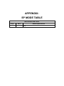
CTL Maintenance
PDL Mode
ON = "PDL Settings" is shown (Default)
OFF = "PDL Settings" is hidden
System
Maintenance
Reference
CTL Maintenance
SM
5-11
M116/M117
Configuration and Maintenance Page
5.2 CONFIGURATION AND MAINTENANCE PAGE
5.2.1 OVERVIEW
The configuration page and maintenance page have information about the machine's status. Print
this sheet as shown below. Check the configuration page or maintenance page when doing
machine maintenance.
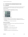
To Print the Configuration Page/ Maintenance Page
1.
Turn on the machine.
1.
Press the "Menu" key.
2.
Press the "Up" or "Down" key to select "List/Test Print", and then press the "OK" key.
3.
Press the "Up" or "Down" key to select "Config. Page" or "Maintenance Pg.", and then press
the "OK" key.
4.
The configuration page or maintenance page is printed.
Other Types of Reports
You can also check other reports than two reports (configuration page and maintenance page)
with "List/Test Print" in the "Menu ".
Menu List
Prints the menu list showing all available menus.
Dup. Test Page
Prints a test page for checking the duplex printing condition.
PCL Font List
Prints the current configuration and installed PCL font list.
PS. Font List
Prints the current configuration and installed PostScript font list.
M116/M117
5-12
SM
Configuration and Maintenance Page
Total Counter
Total Counter:
The total counter incremented by the "engine controller board" each time the board issues a
print command to the engine.
The value is calculated as follows:
Total counter = Printer counter + Reports print
Application Counters:
Application counters exist for each individual primary machine function, and are incremented by
System
Maintenance
Reference
the "controller board" each time the board issues a print request for the function in question.
SM
5-13
M116/M117
Firmware Updating
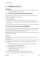
5.3 FIRMWARE UPDATING
Never turn the machine's main power off while the firmware is being updated, as this
could damage the ECB or controller board.
5.3.1 CHECKING THE MACHINE FIRMWARE VERSION
To update the firmware for this machine, you need the most recent version of the firmware
(firmware file downloadable from the Internet).
1.
Turn on the machine.
2.
Press the "Menu" key.
3.
Press the "Up" or "Down" key to select "List/Test Print", and then press the "OK" key.
4.
Press the "Up" or "Down" key to select "Config. Page" or "Maintenance Pg.", and then press
the "OK" key.
5.
Check the "Firmware Version” (Controller) and "Engine FW version" on the list of the pages.
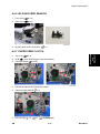
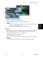
5.3.2 UPDATING THE CONTROLLER FIRMWARE
Using the following procedure to update the controller firmware, be sure to print the configuration
page both before and after the update. Comparing pre- and post-update configuration pages
allows you to check whether or not the update was successful.
Follow the procedure carefully, and note that it will vary in parts depending on which version of the
firmware is currently installed.
Procedure
When updating firmware, always disconnect any other cable(s) than the one being used for the
update operation.
(When updating firmware via USB cable, first disconnect any network and phone line cables, and
when updating firmware via LAN cable, first disconnect any USB and phone line cables.)
1.
2.
Prepare:
Computer: Windows XP/Vista/7, Windows Server 2003/2003 R2, 2008/2008 R2
USB cable or LAN (Local Area Network) cable
Download the firmware files to your computer.
FwUpdateToolSP.exe (Service Mode execute file)
Setting.ini (Parameter setting)
xxx.brn (Controller Firmware)
3.
Make a folder on a local drive of your computer and save the files there.
4.
Connect a computer and the machine through a network or directly by USB.
M116/M117
5-14
SM
Firmware Updating
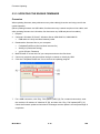
5.
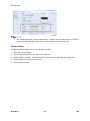
Click the "FWUpdateToolSP.exe" file to execute the updating program.
6.
For a USB connection, click "F/W Update (USB)" [A]. For a network connection, enter the
machine's IP address in "Machine IP" [B], and then click "F/W Update (NET)" [C].
Check the firmware update tool window for messages and the update’s current percentage of
completion.
Do not turn the main power off from this point until the update procedure is
completed.
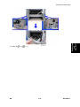
7.
Wait until “FW Update Done.***Please reboot the Machine.***” appears in the firmware
update tool window. Also check that update completion message appears on the machine’s
control panel.
8.
Turn off the power of the machine, and then turn it back on.
9.
Print a configuration or maintenance page to check the machine's firmware version.
SM
5-15
M116/M117
System
Maintenance
Reference
Firmware Updating
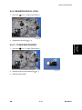
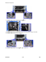
5.3.3 UPDATING THE ENGINE FIRMWARE
Procedure
When updating firmware, always disconnect any other cable(s) than the one being used for the
update operation.
(When updating firmware via USB cable, first disconnect any network and phone line cables, and
when updating firmware via LAN cable, first disconnect any USB and phone line cables.)
1.
Prepare:
2.
Computer: Windows XP/Vista/7, Windows Server 2003/2003 R2, 2008/2008 R2
3.
USB cable or LAN (Local Area Network) cable
Download the firmware files to your computer.
FwUpdateToolSP.exe (Service Mode execute file)
Setting.ini (Parameter setting)
yyy.bin (Engine Firmware)
4.
Make a folder on a local drive of your computer and save the files there.
5.
Connect a computer and the machine through a network or directly by USB.
6.
Click the "FWUpdateToolSP.exe" file to execute the updating program.
7.
For a USB connection, click "Eng. F/W Update (USB)" [A]. For a network connection, enter
the machine's IP address in "Machine IP" [B], and then click "Eng. F/W Update (NET)" [C].
Check the firmware update tool window for messages and the update’s current percentage of
completion.
M116/M117
5-16
SM
Firmware Updating
8.
You will see the progress percentage appear while the update is in progress.
Do NOT turn the main power of the machine off during updating.
Wait until “FW Update Done.***Please reboot the Machine.***” appears in the firmware
update tool window. Also check that update completion message appears on the machine’s
control panel.
9.
Turn off the power of the machine, and then turn it back on.
10. Print a configuration or maintenance page to check the machine's firmware version.
5.3.4 UPDATING THE BOOT LOADER FIRMWARE
This is also listed on the configuration page, but this firmware is not updated in the field.
5.3.5 UPDATING FAILURE
If the firmware update is not successful, the update process is suspended and an error message
should display on the FW Update Tool screen. If this happens, DO NOT turn off the machine, and
execute the update procedure again (unless the error message "Downloaded file is broken! Do
NOT use print, scan, fax and copy function at the same time." is displayed).
If power is turned off accidentally during a firmware update, the firmware will not be correctly
updated, and the machine may not start up normally. If the machine does not start up normally, the
When the machine does not start up normally, in most cases, the panel display will indicate one of
the following two conditions:
When attempting to restart the machine, the LCD panel display indicates "Initializing"
indefinitely.
In this case, the controller firmware update has failed. The controller firmware must be
updated again.
When attempting to restart the machine, the LCD panel display indicates "Please Download
Engine FW Again!"
In this case, the engine firmware update has failed. The engine firmware must be updated again.
SM
5-17
M116/M117
System
Maintenance
Reference
controller firmware and/or the engine firmware will need to be updated again.
Firmware Updating
5.3.6 FW UPDATE TOOL MESSAGES
FW Update Tool Messages: Information
Message for USB update
Messages
USB Upload : End of data
Comment
Action
Send F/W file to Printer
Please reboot Printer after
successfully.
panel shows reboot
(Transmission Time: <30 sec)
message.
Check USB cable
connection.
USB Upload : FAIL
Can not open USB printer
Check the installation of
driver while F/W file is
USB Print Driver if it is
transmitted.
available.
Check Printer status if it is
available.
Check USB cable
F/W file transmission can not
connection.
be completed.
Check USB Print Driver if it
(Transmission will be canceled is available.
Check Printer status if it is
if timeout.)
available.
Check the download file
name in setting.ini.
Can't open ROM
file.Please check ROM file.
F/W file does not exist.
"ImageFile="
Check the download file
and fw update tool is in the
same folder.
Check the download file
name in setting.ini.
Can't open Eng. ROM file.
Please check Eng. ROM
Engine F/W file does not exist.
file.
"EngImageFile="
Check the download file
and fw update tool is in the
same folder.
M116/M117
5-18
SM
Firmware Updating
Messages
New Version: Update FW
Eng FW version: Update
Eng FW
Firmware is Updating...
Eng Firmware is
Updating...
Comment
AIO FW is transmitting
Not available
Engine FW is transmitting
Not available
AIO FW is updating
Not available
Engine FW is updating
Not available
FW Update Done. ***
Please reboot the
Action
F/W update is completed.
Machine.***
Please reboot the
Machine.
Message for Network update
Connecting…
Net Upload : End of data
Comment
Connect to Printer.
Update F/W successfully.
(Transmission Time: <30 sec)
Action
Please wait a moment.
Please reboot Printer after
panel shows reboot
message.
(1) Check network cable
Can not open FTP port of
Printer before F/W file is
Net Upload : FAIL
transmitted.
(Transmission will be canceled
if timeout.)
connection.
(2) Check Printer status if it
is available.
(3) Check Printer and PC
IP address setting.
(4) Check PC firewall
setting about FTP.
F/W file transmission can not
(1) Check network cable
be completed.
connection.
(Transmission will be canceled (2) Check Printer status if it
if timeout.)
SM
is available.
5-19
M116/M117
System
Maintenance
Reference
Messages
Firmware Updating
Messages
Comment
Action
Check the download file
name in setting.ini.
Can't open ROM file.
Please check ROM file.
F/W file does not exist.
"ImageFile="
Check the download file
and fw update tool is in the
same folder.
Check the download file
name in setting.ini.
Can't open Eng. ROM file.
Please check Eng. ROM
Engine F/W file does not exist.
file.
"EngImageFile="
Check the download file
and fw update tool is in the
same folder.
New Version: Update FW
Eng FW version: Update
Eng FW
Firmware is Updating...
Eng Firmware is
Updating...
AIO FW is transmitting
Not available
Engine FW is transmitting
Not available
AIO FW is updating
Not available
Engine FW is updating
Not available
FW Update Done. ***
Please reboot the
F/W update is completed.
Machine.***
M116/M117
5-20
Please reboot the
Machine.
SM
Firmware Updating
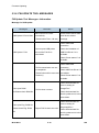
FW Update Tool Messages: Error
Message for USB update
Messages
Comment
Action
Check USB cable
connection.
Can not get Printer status form Check USB Print Driver if it
Machine is not ready.
USB status channel before
is available.
F/W file is transmitted.
Do not update F/W when
Printer is in power-on
stage.
current machine.
F/W update is running.
Machine is busy.
Other Printer functions are
running.
of F/W file and machine if it
is suitable for Printer.
Please wait F/W update is
completed.
Please wait other Printer
functions are completed.
FW Update Done. ***
Please reboot the
Please check the version
F/W update is completed.
Machine.***
Machine loses
Please reboot the
Machine.
Do not reboot engine till
communication. ***Please
F/W file has transmitted.
Engine Panel display
check FW Update Done.
Polling F/W update progress
"Firmware Update Done.
Then reboot the
fail.
Please reboot". Then
Machine.***
Downloaded file is broken!
Do NOT use print, scan,
fax and copy function at
the same time.
reboot engine.
Check the downloaded file
F/W checks the downloaded
is not broken.
file. And get wrong checksum.
Do not use Printer
So stop to modify F/W.
functions when update
firmware.
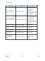
Message for Network update
SM
5-21
M116/M117
System
Maintenance
Reference
Wrong Model.
F/W file is not matched for
Firmware Updating
Messages
Comment
Action
Check PC network settings
and IP address.
Can not get Printer status form Check Printer network
Machine is not ready.
Network status channel before settings and IP address.
F/W file is transmitted.
Do not update F/W when
Printer is in power-on
stage.
Wrong Model.
F/W file is not matched for
current machine.
F/W update is running.
Machine is busy.
Other Printer functions are
running.
of F/W file and machine if it
is suitable for Printer.
Please wait F/W update is
completed.
Please wait other Printer
functions are completed.
FW Update Done. ***
Please reboot the
Please check the version
F/W update is completed.
Machine.***
Machine loses
Please reboot the
Machine.
Do not reboot engine till
communication. ***Please
F/W file has transmitted.
Engine Panel display
check FW Update Done.
Polling F/W update progress
"Firmware Update Done.
Then reboot the
fail.
Please reboot". Then
Machine.***
Downloaded file is broken!
Do NOT use print, scan,
fax and copy function at
the same time.
M116/M117
reboot engine.
Check the downloaded file
F/W checks the downloaded
is not broken.
file. And get wrong checksum.
Do not use Printer
So stop to modify F/W.
functions when update
firmware.
5-22
SM
TROUBLESHOOTING
R E V I S I O N H I S T O RY
Pag e
Date
Ad d ed / Upd ated / New
None
Service Call Conditions
6. TROUBLESHOOTING
6.1 SERVICE CALL CONDITIONS
See "Appendices" for the "Error Message".
6.1.1 SUMMARY
This machine issues an SC (Service Call) code if an error occurs with the machine. The error
code can be seen on the operation panel.
Make sure that you understand the following points;
1.
All SCs are logged.
2.
At first, always turn the main switch off and on if an SC code is displayed.
3.
First, disconnect then reconnect the connectors before replacing the PCBs (if the problem
concerns electrical circuit boards).
4.
First, check the mechanical load before replacing motors or sensors (if the problem concerns
a locked motor).
Fusing related SCs
To prevent damage to the machine, the main machine cannot be operated until the fusing related
SC has been reset by a service representative.
Enter the "Eng Maintenance" in the “Service Mode”.
Press "O.K" in "Fuser SC Reset" with engine maintenance mode, and then turn the main power
Troubleshooting
switch off and on.
SM
6-1
M116/M117
Service Call Conditions
6.1.2 ENGINE SC
SC 2xx (Laser Optics Error)
Polygon motor on timeout error
202
The polygon mirror motor does not reach the targeted operating speed within 10
sec. after turning.
Polygon motor off timeout error
203
The polygon mirror motor does not leave the READY status within 20 sec. after
the polygon mirror motor switched off.
Polygon motor lock signal error
The signal remains HIGH for 200 ms (or 4times in 50msec polling) while the
polygon mirror motor is rotating.
204
Polygon motor/driver board harness loose or disconnected
Polygon motor/driver board defective
Laser optics unit defective
1.
Turn the main power off/on the machine.
2.
Replace the interface harness of the laser optics unit.
3.
Replace the laser optics unit.
Beam Synchronize error
The laser synchronizing detection signal for LD is not output within 400msec after
the LD unit has turned on.
220
Disconnected cable from the laser synchronizing detection unit or defective
connection
Defective laser synchronizing detector
Defective LD
Defective ECB
1.
Check the connectors.
2.
Replace the laser optics unit.
3.
Replace the ECB.
M116/M117
6-2
SM
Service Call Conditions
Laser Scanning Unit thermistor error
At power on, the temperature sensor in the optics unit detected a temperature
lower than -30°C for more than 4 sec.
-or268
It detected a temperature higher than 105°C for more than 1sec.
Thermistor disconnected (causes extremely low temperature reading)
Thermistor damaged and short circuited (causes extremely high temperature
reading)
1.
Turn the machine's main power off, and then on.
2.
Replace the thermistor.
SC 4xx (Image Transfer and Transfer Error)
Bias leak
An error signal is detected for 0.2 seconds when changing the development unit.
Defective transfer roller
Defective high voltage power pack
1.
Turn the machine's main power off, and then on.
Troubleshooting
491
SM
6-3
M116/M117
Service Call Conditions
SC 5xx (Motor and Fusing Error)
Main motor error
The machine does not detect a main motor lock signal within 2sec after the main
motor started to rotate.
-orThe machine does not release a main motor lock signal within 2sec after the main
motor switched off.
-or500
The machine detects a main motor lock signal every 100ms for seven times
consecutively, after the main motor started to rotate stably.
Overload of
Torque load overload
Defective main motor
Disconnect or defective motor harness
1.
Turn the machine's main power off, and then on.
2.
Check or replace the main motor if the torque load is normal.
3.
Replace the motor harness.
Exhaust fun Error
530
The FAN lock signal – High for 10 seconds, after the fan motor started to rotate.
Disconnected or defective motor harness.
1.
Turn the machine's main power off, and then on.
Fuser thermistor error
541
The thermistor output is less than 0°C for 5 seconds after the fusing lamp turns
ON.
M116/M117
6-4
SM
Service Call Conditions
Disconnected or defective thermistor
Disconnected or defective fusing lamp
1.
Check the harness connection of the thermistor.
2.
Replace the fusing unit.
Execute "Fuser SC Reset" to recover the machine after completing the
recovery procedure. Otherwise, the machine continues to issue this SC
code and cannot be operated.
Fuser reload error
This SC is issued if one of following conditions occurs:
The fusing temperature rises 8°C or less in 1.5 seconds; and this continues 5
times consecutively.
-orThe fusing temperature has not reached 45°C within 9 seconds (after the fusing
542
lamp comes ON while the machine is warming-up).
-orThe fusing unit does not attain reload temperature within 35 s. (normal
temperature) or 65 s (lower temperature – the thermistor output is less than 18°C)
after the fusing temperature control starts.
Defective or deformed thermistor
Incorrect power supply input at the main power socket
1.
Defective fusing lamp
Troubleshooting
High temperature error (Soft)
The detected temperature stays at 225°C for 1 second, and this
consecutively occurs 10 times.
543
Defective ECB
Defective PSU
1.
Replace the ECB
2.
Replace the PSU
Execute "Fuser SC Reset" to recover the machine after completing the
recovery procedure. Otherwise, the machine continues to issue this SC
code and cannot be operated.
SM
6-5
M116/M117
Service Call Conditions
High temperature error (hard)
During stand-by mode or a print job, the detected heating roller temperature
reaches 250°C.
544
Defective ECB
Defective PSU
1.
Replace the ECB
2.
Replace the PSU
Execute "Fuser SC Reset" to recover the machine after completing the
recovery procedure. Otherwise, the machine continues to issue this SC
code and cannot be operated.
Fuser full heater error
The fuser full heater remained ON at full capacity for more than 9 s after the
fusing temperature attains reload temperature.
545
Deformed thermistor
Thermistor not in the correct position
Defective fusing lamp
1.
Replace the fusing unit.
2.
Replace the fusing lamp.
Execute "Fuser SC Reset" to recover the machine after completing the
recovery procedure. Otherwise, the machine continues to issue this SC
code and cannot be operated.
M116/M117
6-6
SM
Service Call Conditions
Zero cross error
The zero cross signal is detected three times even though the fusing lamp
relay is off when turning on the main power.
The zero cross signal is not detected for 3 seconds even though the fusing
lamp relay is on after turning on the main power or closing the front door.
The detection error occurs twice or more in 11 zero cross signal detections.
This error is defined when the detected zero cross signal is less than 45.
547
The zero cross signal is not detected three times while the main power
remains ON.
Defective fusing relay
Defective fusing relay circuit
Shorted +24V fuse on the PSU
Unstable power supply.
1.
Check the power supply source.
2.
Replace the +24V fuse on the PSU.
3.
Replace the PSU
Fuser 3times jam error
The paper jam counter for the fusing unit reaches 3. The paper jam counter is
cleared if the paper is fed correctly.
This SC is activated only when this function is enabled with "Eng. Maintenance"
559
Defective fusing unit
Defective fusing control
1.
Clear this SC to send a command after a jam removal.
2.
Turn off this function after a jam removal.
Troubleshooting
(default "OFF").
Execute "Fuser SC Reset" to recover the machine after completing the
recovery procedure. Otherwise, the machine continues to issue this SC
code and cannot be operated.
SM
6-7
M116/M117
Service Call Conditions
SC 6xx (Communication and Other Error)
EEPROM communication error
An unexpected value exists in the initialization flag of the EEPROM
669
EEPROM not connected
Defective EEPROM
1.
Installing the EEPROM.
2.
Replacing the EEPROM.
CTL_PRREQ_N signal does not come.
The ECB does not receive a memory address command from the controller 20
seconds after paper is in the position for registration.
688
Defective controller board
Communication error
1.
Turn the machine's main power off, and then on.
2.
Check if the controller board is firmly connected to the ECB.
M116/M117
6-8
SM
Image Problems
6.2 IMAGE PROBLEMS
6.2.1 OVERVIEW
Image problems may appear at regular intervals that depend on the circumference of certain
components. The following diagram shows the possible symptoms (black or white dots at regular
intervals).
Abnormal image at 29.8 mm intervals: Charge roller
Abnormal image at 37.7 mm intervals: Registration roller
Colored spots at 37.9 mm intervals: Print cartridge (Development roller)
Abnormal image at 45.8 mm intervals: Transfer roller
Colored spots at 75.3 mm intervals: Print cartridge (OPC drum)
Abnormal image at 94.2 mm intervals: Fusing unit (Pressure roller)
Abnormal image at 93.1 mm intervals: Fusing unit (Hot roller)
Abnormal image at 100.5 mm intervals: Paper feed roller
Troubleshooting
SM
6-9
M116/M117
Image Problems
6.2.2 TEST PAGE PRINTING
When you check an image problem or other problems, it might be necessary to print a test page.
Follow the test page print procedure below to print a test page.
Test Page Print Procedure
1.
Press the "Menu".
2.
Press the "Up" or "Down" keys to select "List/Test Print" and then press the "OK" key.
3.
Press the "Up" or "Down" keys to select "Test Page" and then press the "OK" key.
Test page sample
6.2.3 TEST PATTERN PRINTING
Follow the test pattern print procedure below to print a test pattern.
Test Pattern Print Procedure
1.
Enter the "Service Mode".
2.
Select "Eng Maintenance", and then press "OK" key.
3.
Select "Test Pattern", and then press "OK" key.
4.
The following three test pattern pages (Checker flag/ Grid pattern/ Trimming pattern) are
printed.
Test pattern samples
M116/M117
6-10
SM
Image Problems
6.2.4 DARK LINES IN HALFTONE AREAS AT 75MM INTERVALS
Using the machine in a room where the humidity level is too low may cause dark lines in halftone
areas at 75mm intervals. This is because low-humidity conditions tend to cause variations in light
sensitivity across the surface of the drum.
Selecting [On] for [Low Humid. Mode] under the [Maintenance] (Menu) may help to prevent these
lines from appearing.
When the humidity mode setting is enabled, the drum is rotated slightly every 15 minutes. This
Troubleshooting
keeps the light sensitivity constant across the entire surface of the drum.
SM
6-11
M116/M117
Jam
6.3 JAM
6.3.1 JAM SENSOR LAYOUT
There are the sensors of the jam detection as shown below.
Paper Jam
1.
Registration Sensor
2.
Tray2 Paper Feed Sensor
3.
Inverter Sensor
4.
Paper Exit Sensor
5.
Relay Sensor
M116/M117
6-12
SM
Jam
6.3.2 JAM MESSAGE LIST
Here is a list of common jam messages, a description of the causes.
See the drawing shown above to check the sensor location.
Paper Jam
Related to jam code
Jam message
Cause
Sensor
Paper does not reach
Misfeed: PprTray
registration sensor (bypass
Registration sensor [1]
tray)
Misfeed: Tray 1
Paper does not reach
registration sensor (tray1)
Paper does not reach tray2
convey sensor
Registration sensor [1]
Tray2 paper feed sensor [2]
Misfeed: Tray 2
Paper does not reach
registration sensor
Registration sensor [1]
Paper does not reach
registration sensor (duplex
Registration sensor [1]
feed tray)
Paper does not reach
duplex entry sensor
Paper does not reach
duplex exit sensor
Paper stayed on registration
sensor
Relay sensor [5]
Troubleshooting
Misfd: Dupl Unit
Inverter sensor [3]
Registration sensor [1]
Internal Misfeed
Paper does not reach exit
sensor
Misfd: Stnd Tray
Paper exit sensor [4]
Paper stayed on exit sensor Paper exit sensor [4]
Related to initialize jam
SM
6-13
M116/M117
Jam
Jam message
Cause
Misfeed: Tray 2
Tray2 paper feed sensor [2]
Internal Misfeed
Registration sensor [1]
Misfd: Stnd Tray
Paper exit sensor [4]
Relay sensor [5]
Misfd: Dupl Unit
Inverter sensor [3]
M116/M117
6-14
SM
ENERGY SAVER
R E V I S I O N H I S T O RY
Pag e
Date
Ad d ed / Upd ated / New
None
Energy Saver Modes
7. ENERGY SAVER
7.1 ENERGY SAVER MODES
Customers should use energy saver modes properly, to save energy and protect the environment.
The backlight of the screen is turned off and "Energy Saver Mode1" appears on the screen, and
then the fusing lamp is turned off and "Energy Saver Mode2" appears on the screen.
The area shaded grey in this diagram represents the amount of energy that is saved when the
timers are at the default settings. If the timers are changed, then the energy saved will be different.
For example, if the timers are all set to 240 min., the grey area will disappear, and no energy is
saved before 240 min. expires.
7.1.1 TIMER SETTINGS
Energy Saver Mode 1 (30 sec.): This can be only turned on or off.
Energy Saver Mode 2 (1 to 240 min.): This can be turned on or off and timer setting is
adjustable (default: 1min.).
SM
7-1
M116/M117
Energy SaveR
The user can set these timers with Menu (System > Energy Saver 1 or Energy Saver 2)
Energy Saver Modes
7.1.2 RETURN TO STAND-BY MODE
Energy Saver Mode 1
Recovery time: 10 sec.
Energy Saver Mode 2
Recovery time: 20 sec.
7.1.3 RECOMMENDATION
We recommend that the default settings should be kept.
If the customer requests that these settings should be changed, please explain that their
energy costs could increase, and that they should consider the effects on the environment of
extra energy use.
If it is necessary to change the settings, please try to make sure that the Energy Saver Mode
2 Timer is not too long. Try with a shorter setting first, such as 30 min., then go to a longer one
(such as 60 min.) if the customer is not satisfied.
If the timers are all set to the maximum value, the machine will not begin saving energy until
240 minutes has expired after the last job. This means that after the customer has finished
using the machine for the day, energy will be consumed that could otherwise be saved.
M116/M117
7-2
SM
Paper Save
7.2 PAPER SAVE
7.2.1 EFFECTIVENESS OF DUPLEX/COMBINE FUNCTION
Duplexing and the combine functions reduce the amount of paper used. This means that less
energy overall is used for paper production, which improves the environment.
1. Duplex:
Reduce paper volume in half!
2. Combine mode:
Reduce paper volume in half!
Energy SaveR
3. Duplex + Combine:
Using both features together can further reduce paper volume by 3/4!
SM
7-3
M116/M117
Paper Save
To check the paper consumption, look at the total counter and the duplex counter.
The total counter counts all pages printed.
For one duplex page, the total counter goes up by 2.
For a duplex job of a three-page original, the total counter goes up by 3.
The duplex counter counts pages that have images on both sides.
For one duplex page, the duplex counter goes up by 1.
For a duplex job of a three-page original, the duplex counter will only increase by 1, even
though two sheets are used.
Total counter
This machine has a total sides printed counter only (so a duplex print is counted as two, not one).
You can check the total counter in the "Service Mode" or the “Menu”.
Service Mode
"Eng Maintenance" > "Total Counter" > "Engine Counter"
Menu
“List/Test Print” > “Config. Page” or “Maintenance Pg.”
The following table shows paper savings and how the counters increase for some simple
examples of single-sided and duplex jobs
M116/M117
7-4
SM
Paper Save
Duplex mode:
Simplex Sheet
Duplex
Paper
used
Sheets used
Saved
1
1
1
0
1
2
2
1
1
2
3
3
2
1
3
4
4
2
2
4
5
5
3
2
5
10
10
5
5
10
20
20
10
10
20
Originals
Total counter
If combine mode is used, the total and duplex counters work in the same way as explained
previously. The following table shows paper savings and how the counters increase for some
simple examples of duplex/combine jobs.
2 in 1 mode:
Simplex Sheet
Duplex
Paper
used
Sheets used
Saved
1
1
1
0
1
2
2
1
1
1
3
3
2
1
2
4
4
2
2
2
5
5
3
2
3
10
10
5
5
5
20
20
10
10
10
SM
7-5
Total counter
Energy SaveR
Originals
M116/M117
Paper Save
Duplex + 2 in 1 mode:
Simplex Sheet
Duplex
Paper
used
Sheets used
Saved
1
1
1
0
1
2
2
1
1
1
3
3
1
2
2
4
4
1
3
2
5
5
2
3
3
6
6
2
4
3
7
7
2
5
4
8
8
2
6
4
9
9
3
6
5
10
10
3
7
5
11
11
3
8
6
12
12
3
9
6
Originals
M116/M117
7-6
Total counter
SM
M116/M117
SERVICE MANUAL APPENDICES
M116/M117 APPENDICES
TABLE OF CONTENTS
1. APPENDIX: SPECIFICATIONS .................................................... 1-1
1.1 GENERAL SPECIFICATIONS ................................................................... 1-1
1.1.1 GENERAL SPECIFICATIONS .......................................................... 1-1
1.1.2 PRINTER .......................................................................................... 1-3
1.2 SUPPORTED PAPER SIZES .................................................................... 1-4
2. APPENDIX: SP MODE TABLE ..................................................... 2-1
2.1 SERVICE MENU ........................................................................................ 2-1
3. APPENDIX: TROUBLESHOOTING GUIDE ................................. 3-1
3.1 SERVICE CALL CONDITIONS .................................................................. 3-1
3.2 ERROR MESSAGES ................................................................................. 3-2
3.2.1 OVERVIEW ...................................................................................... 3-2
3.2.2 ERROR MESSAGES LIST ............................................................... 3-2
SM Appendix
i
M116/M117
APPENDIX:
SPECIFICATIONS
R E V I S I O N H I S T O RY
Pag e
Date
Ad d ed / Upd ated / New
None
General Specifications
Appendix:
Specifications
1. APPENDIX: SPECIFICATIONS
1.1 GENERAL SPECIFICATIONS
1.1.1 GENERAL SPECIFICATIONS
Configuration
Desktop
Main tray
250 sheets (80g/m 2)
100 postcards
50 sheets (80g/m 2)
By-pass tray
Paper capacity
8 envelopes
20 postcards
Optional paper feed
unit
Output tray
Plain paper: 250 sheets (80g/m 2)
Face down: 125 sheets
A4, Letter, Legal, B5, A5, A6, HLT,
Executive, Foolscap, Folio, Postcard
Main tray
Custom size:
Max: 216 x 356mm (8.5 x 14 inch)
Min: 100 x 148mm (3.937 x 5.8 inch)
A4, Letter, Legal, B5, A5, A6, HLT,
Executive, Foolscap, Folio, Postcard,
Paper size
By-pass tray
Envelope
Custom size:
Max.: 216 x 356mm (8.5 x 14 inch)
Min.: 90 x 148mm (3.5 x 5.8 inch)
Duplex
Optional paper feed
unit
SM Appendix
A4, Letter, Legal
A4, LT, LG, B5, HLT, A5
1-1
M116/M117
General Specifications
Main tray
52-162 g/m 2 (14-43 lb)
By-pass tray
52-162 g/m 2 (14-43 lb)
60-105 g/m 2 (16-28 lb)
A setting for outside of normal
Paper weight
specifications paper (60 g/m 2 - 105 g/m 2)
Optional paper feed
is provided.
unit
With this setting, it may be possible to
print properly on outside of normal
specifications paper.
Machine size
370 x 392 x 262 mm (14.6 x 15.5 x 10.4 inch)
(W x D x H)
Without Option
M116: 11.7 kg(25.8 lb)
Weight
M117: 12.7 kg(28.0 lb)
With a starter AIO cartridge.
Energy Saver Mode
Selectable 1 to 240 minutes (1 minute steps)
NA/TW: Less than 850 W
Maximum
Ready mode
Power save mode
Noise
M116/M117
EU/AP/CN: Less than 895 W (energy
star compliant)
Power consumption
Power
(energy star compliant)
120W
70 W (energy saver mode1)
10 W (energy saver mode2)
NA
120 V, 60Hz ± 3Hz
TW
110 V, 60Hz ± 3Hz
EU/AP/CN
220 - 240 V, 50/60Hz ± 3Hz
Printing
Less than 65.8 dB (A)
Standby Mode
Less than 40 dB (A)
Energy Save Mode
Less than 40 dB (A)
1-2
SM Appendix
Warm up time
Less than 20 seconds
Machine life
5 years, 350,000 prints (whichever comes first)
Environmental
Standard
Laser type
Appendix:
Specifications
General Specifications
Energy star program (M117)
Class I
1.1.2 PRINTER
Simplex
Print speed
30 ppm LT, 28 ppm A4 (600 dpi)
Duplex
15 ppm LT, 14 ppm A4 (600 dpi)
(M117 only)
Printer drivers
PCL, PS3
Font
80 fonts
Resolution
1200 x 1200, 600 x 600 dpi
Toner save mode
Supported
First print time
Less than 8 seconds
Duplex print
Supported (M117 only)
PC interface
USB2.0, 10BASE-T/100BASE-TX
Network
Protocol
TCP/IP, IPP
Memory
Standard
64 MB
PCL: Windows XP/Vista/7 and Windows Server 2003/2003
Operation System
R2/2008/2008 R2
PS3: Windows XP/Vista/7 and Windows Server 2003/2003
R2/2008/2008 R2, and Mac OS X 10.3 or later
SM Appendix
1-3
M116/M117
Supported Paper Sizes
1.2 SUPPORTED PAPER SIZES
A
B
Supported, with size molded into tray. Need to select paper size by
operation panel/driver.
Supported but size is not molded into tray. Need to select paper size by
operation panel/driver.
C
Need to input paper size by operation panel and driver.
N
Not supported.
Input Tray
Type
SEF/
LEF
Size
Auto
Standard
Option
Bypass
Tray
PFU
Tray
Duplex
A4
SEF
210x297
A
A
B
B
B5
SEF
182x257
A
A
B
N
SEF
148x210
A
A
B
N
LEF
210x148
N
N
C
N
SEF
128x182
B
N
B
N
LEF
182x128
N
N
N
N
SEF
105x148
B
N
B
N
LEF
148x105
N
N
N
N
SEF
100 x 148
C
N
C
N
LEF
148 x 100
N
N
N
N
SEF
200 x 148
C
N
C
N
LEF
148 x 200
C
N
C
N
Legal
SEF
81/2"x14"
A
A
B
B
Letter
SEF
81/2"x11"
A
A
B
B
A5
B6
A6
Postcard
M116/M117
1-4
SM Appendix
Input Tray
Type
SEF/
LEF
Size
Auto
Standard
Option
Bypass
Tray
PFU
Tray
Duplex
SEF
51/2" x 81/2"
B
B
B
N
LEF
81/2" x 51/2"
N
N
N
N
Executive
SEF
71/4"x101/2"
A
N
B
N
F
SEF
8" x 13"
B
N
N
N
Foolscap
SEF
81/2" x 13"
B
N
N
N
Folio
SEF
81/4" x 13"
B
N
N
N
16 Kai
SEF
195 x 267
B
N
B
N
Env. #10
SEF
41/8" x 91/2"
N
N
B
N
SEF
37/8" x 71/2"
N
N
B
N
Env. C5
SEF
162 x 229
N
N
B
N
Env. C6
SEF
114 x 162
N
N
B
N
Env. DL
SEF
110 x 220
N
N
B
N
Width
100-216mm
C
N
C
N
Length
148-356mm
C
N
C
N
Width
90-216mm
N
N
C
N
Length
140-356mm
N
N
C
N
Half Letter
Env.
Monarch
SM Appendix
1-5
M116/M117
Appendix:
Specifications
Supported Paper Sizes
APPENDIX:
SP MODE TABLE
R E V I S I O N H I S T O RY
Pag e
Date
Ad d ed / Upd ated / New
None
Service Menu
2. APPENDIX: SP MODE TABLE
2.1 SERVICE MENU
Appendix:
SP Mode
Table
See "Main Chapters" for "Service Program Mode".
SM Appendix
2-1
M116/M117
APPENDIX:
TROUBLESHOOTING GUIDE
R E V I S I O N H I S T O RY
Pag e
Date
Ad d ed / Upd ated / New
None
Service Call Conditions
3. APPENDIX: TROUBLESHOOTING GUIDE
3.1 SERVICE CALL CONDITIONS
Appendix:
TroubleShooting
Guide
See “Main Chapters” for "Service Call Conditions".
SM Appendix
3-1
M116/M117
Error Messages
3.2 ERROR MESSAGES
3.2.1 OVERVIEW
Error messages will be displayed on the LCD panel if the machine has a problem. These can be
viewed by a customer.
3.2.2 ERROR MESSAGES LIST
Message
Cover open
Controller FW
download failed
Causes
Solutions
The front cover is open.
Open and then close the front cover.
Controller FW could not be
downloaded.
Turn off the main power, turn it back
on, and then download the controller
FW again.
Incor Prt Cart
Irregular toner is set.
Replace the toner to appropriate one.
Internal Misfeed
There is a paper jam in the
Remove the jammed paper.
fusing unit.
See the user’s guide.
Load Paper #
Load paper into the indicated paper
The indicated tray # (1, 2,
tray.
bypass) is out of paper.
See the user’s guide.
Memory
This error occurs when FW
Overflow
memory is not enough to save
the printing page.
Misfeed: Tray 1
Reduce the size of the data, and then
try the operation again.
Paper has been jammed in
Remove the jammed paper.
the tray 1 paper input area.
See the user’s guide.
Paper has been jammed in
Remove the jammed paper.
the tray 2 paper input area.
See the user’s guide.
Misfd:
There is a paper jam in
Remove the jammed paper.
BypssTray
Bypass tray.
See the user’s guide.
Misfd: Dupl Unit
There is a paper jam in the
Remove the jammed paper.
duplex unit.
See the user’s guide.
Misfeed: Tray 2
M116/M117
3-2
SM Appendix
Error Messages
Misfd: Stnd Tray
Causes
Solutions
There is a paper jam in the
Remove the jammed paper.
paper exit area.
See User Guide.
Replace Fusing
It is time to replace the Fusing Replace the Fusing unit.
Unit
unit.
Replace Ppr.
It is time to replace the paper
Feed Roller
feed roller.
Replace Print
Cartridge
p.2-1 "Service Menu"
Replace the paper feed roller.
p.2-1 "Service Menu"
Replace the print cartridge.
The printer is out of toner.
See the user’s guide.
Replace soon
The printer is almost out of
Print Cartridge
tonner .
Replace
It is time to replace the
Transfer Roller
transfer roller.
Reset Tray 1
The indicated paper input tray
Prepare a new print cartridge.
Replace the transfer roller.
p.2-1 "Service Menu"
1 is not installed correctly, or
not installed.
Install the indicated paper input tray 1
correctly.
Service call
There is a problem with the
SCXXX
printer's controller.
Set Er: Prt Cart
The indicated print cartridge is Set the indicated print cartridge
Size Msmtch: #
Start/JobReset
p.3-1 "Service Call Conditions"
not set correctly, or not set.
correctly.
The error message appears
Using a dry cloth, carefully wipe the
even though the print
interface area on the print cartridge
cartridge is set correctly.
surface.
The paper size setting in the
tray # (1, 2, bypass) differs
from that of actual paper size
in the tray.
SM Appendix
Appendix:
TroubleShooting
Guide
Message
Load paper of the selected size in the
tray, and then press the [Stop/Start]
key to continue printing.
Press the [Job Reset] key to cancel
printing.
3-3
M116/M117
Error Messages
Message
TypeMsmtch: #
Start/JobReset
Causes
Solutions
The paper type setting in the
tray # (1, 2, bypass) differs
from that of actual paper type
in the tray.
M116/M117
Load paper of the selected type in the
tray, and then press the [Stop/Start]
key to continue printing.
Press the [Job Reset] key to cancel
printing.
3-4
SM Appendix
(M355)
PAPER FEED UNIT TK 1080
R E V I S I O N H I S T O RY
Pag e
Date
Ad d ed / Upd ated / New
None
(M355) Paper Feed Unit TK 1080
TABLE OF CONTENTS
1. REPLACEMENT AND ADJUSTMENT ..........................................1-1
1.1 EXTERNAL COVERS AND PAPER FEED UNIT....................................... 1-1
1.1.1 REAR COVER .................................................................................. 1-1
1.1.2 RIGHT COVER ................................................................................. 1-2
1.1.3 PAPER FEED UNIT .......................................................................... 1-2
1.2 PAPER FEED ROLLER ............................................................................. 1-4
1.2.1 PAPER FEED ROLLER .................................................................... 1-4
Reinstall the paper feed roller............................................................... 1-5
1.3 FRICTION PAD .......................................................................................... 1-6
1.3.1 FRICTION PAD................................................................................. 1-6
1.4 PAPER FEED MOTOR AND GEARS ........................................................ 1-7
1.4.1 PAPER FEED MOTOR ..................................................................... 1-7
1.4.2 PAPER FEED GEARS ...................................................................... 1-8
1.5 PAPER TRAY BOARD ............................................................................... 1-9
1.5.1 PAPER TRAY BOARD...................................................................... 1-9
1.6 PAPER TRAY UNIT SET SWITCH .......................................................... 1-10
1.6.1 PAPER TRAY UNIT SET SWITCH ................................................. 1-10
1.7 SENSORS................................................................................................ 1-11
1.7.1 PAPER FEED SENSOR ................................................................. 1-11
1.7.2 PAPER END SENSOR ................................................................... 1-11
SM
i
M355
Read This First
Safety and Symbols
Replacement Procedure Safety
Turn off the main power switch and unplug the machine before beginning any of
the replacement procedures in this manual.
Symbols Used in this Manual
This manual uses the following symbols.
: See or Refer to
: Screws
: Connector
: Clamp
: Clip ring
: E-ring
REPLACEMENT AND ADJUSTMENT
External Covers and Paper Feed Unit
1. REPLACEMENT AND ADJUSTMENT
Turn off the main power switch and unplug the machine before attempting any
procedure in this section.
1.1.1 REAR COVER
1.
Remove the paper tray unit from the main unit.
2.
Pull out the paper tray.
3.
Rear cover [A] (
SM
x2).
1-1
M355
Paper Feed
Unit TK1080
(M355)
1.1 EXTERNAL COVERS AND PAPER FEED UNIT
1.1.2 RIGHT COVER
1.
Rear cover (
2.
Right cover [A] (
1-1)
x2).
1.1.3 PAPER FEED UNIT
1.
Right cover (
2.
Paper feed motor bracket (
3.
Paper feed roller shaft gear [A] (C-ring x1)
M355
p.1-2)
p.1-8)
1-2
SM
Paper Feed
Unit TK1080
(M355)
External Covers and Paper Feed Unit
4.
Release paper feed roller shaft [A] (C-ring x1, bushing x1).
5.
Paper feed unit [A] (
SM
x4)
1-3
M355
1.2 PAPER FEED ROLLER
1.2.1 PAPER FEED ROLLER
Remove the paper feed roller
p.1-2).
1.
Right cover (
2.
Remove a C-ring [A] and a bushing [B].
3.
Release the paper feed roller shaft [A].
M355
1-4
SM
Paper Feed
Unit TK1080
(M355)
Paper Feed Roller
4.
Release the hook [A] and then move the paper feed roller [B] to the right.
Reinstall the paper feed roller
1.
Attach the paper feed roller to the paper feed roller shaft.
2.
Reinstall the paper feed roller shaft correctly.
As shown in the above pictures, the paper feed roller shaft must be installed
behind the feeler [A]. The left picture [B] is correct. The right picture [C] is
incorrect.
3.
SM
Close the right cover first, and then close the rear cover.
1-5
M355
1.3 FRICTION PAD
1.3.1 FRICTION PAD
1.
Pull out the paper tray.
2.
Turn the paper feed unit over, and release two hooks [A].
3.
Turn the unit over again, and remove the friction pad [B].
M355
1-6
SM
Paper Feed Motor and Gears
1.4 PAPER FEED MOTOR AND GEARS
1.
Right cover (
2.
Paper feed motor [A] (
SM
Paper Feed
Unit TK1080
(M355)
1.4.1 PAPER FEED MOTOR
p.1-2)
x2,
x1,
x1)
1-7
M355
1.4.2 PAPER FEED GEARS
1.
Right cover (
2.
Paper feed motor bracket [A] (
3.
Paper feed gears [A] (each C-ring x1)
M355
p.1-2)
x3,
x1,
1-8
x1)
SM
Paper Tray Board
1.5 PAPER TRAY BOARD
1.
Right cover (
2.
Paper Tray Board (
SM
Paper Feed
Unit TK1080
(M355)
1.5.1 PAPER TRAY BOARD
p.1-2)
x2, locking support x2,
1-9
x 4)
M355
1.6 PAPER TRAY UNIT SET SWITCH
1.6.1 PAPER TRAY UNIT SET SWITCH
1.
Paper feed unit (
2.
Feeler [A]
3.
Paper tray unit set switch [A] (hook x2)
M355
p.1-2)
1-10
SM
Sensors
1.7 SENSORS
Paper Feed
Unit TK1080
(M355)
1.7.1 PAPER FEED SENSOR
1.
Right cover (
p.1-2)
2.
Release the actuator [A] from the slot of the paper feed sensor [B]
3.
Paper feed sensor [B] (all hooks,
x1)
1.7.2 PAPER END SENSOR
1.
Right cover (
2.
Release the actuator [A] from the slot of the paper exit sensor [B]
3.
Paper end sensor [B] (all hooks,
SM
p.1-2)
x1)
1-11
M355