1
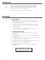
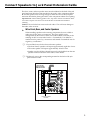
CUSTOM HOME THEATRE
Installation &
Hook-Up Guide
For 35” Built-In System HT35752BD
Important Information
CAUTIONS
• The power cord plugs on all of the
components are polarized (one blade wider
than the other). Be sure any extension cord or
multiple adapter you use is also polarized.
• To prevent electric shock, match wide blade
of plug to wide slot, fully insert.
WARNINGS
• To reduce the risk of fire or shock hazard, do
not expose any of these components to rain or
moisture.
• FCC Regulations state that unauthorized
changes or modifications to this equipment
may void the user’s authority to operate it.
Note: This guide is written with the assumption that the area in
which this system is installed has been built in accordance with
RCA Custom Home Theatre: Construction Guidelines--35” TV
System for this model supplied to the builder or remodeler. It
also assumes that all instructions included in these construction
guidelines have been followed and that the area is complete and
ready to accept the system.
i
Table of Contents
Important Information
Cautions and Warnings . . . . . . . . . . . . . . . . . . . . . . . . . . . . . . . . . . . . i
Get Ready
Unpack System . . . . . . . . . . . . . . . . . . . . . . . . . . . . . . . . . . . . . . . . . . . 2
Check the Installation Area . . . . . . . . . . . . . . . . . . . . . . . . . . . . . . . . 2
Connect Speakers to Jack Panel Extension Cable
Wire Front, Rear, and Center Speakers . . . . . . . . . . . . . . . . . . . . . . .3
Other Connections to Back of Cabinet Area . . . . . . . . . . . . . . . . . . . . . . . . . 4
Install Component and Software Cabinet
Mount Audio/Video Component and Software Cabinet . . . . . . . 5
Install TV Cabinet
Mount TV Cabinet . . . . . . . . . . . . . . . . . . . . . . . . . . . . . . . . . . . . . . . . .6
Install Speakers
Install Left and Right Front Speakers . . . . . . . . . . . . . . . . . . . . . . . . 7
Install Center Speaker . . . . . . . . . . . . . . . . . . . . . . . . . . . . . . . . . . . . . 8
Install Rear Surround Speakers . . . . . . . . . . . . . . . . . . . . . . . . . . . . . 9
Test Trim Frames . . . . . . . . . . . . . . . . . . . . . . . . . . . . . . . . . . . . . . . . . . . . . . . 10
Install Component and Software Cabinet Shelves
Position the Components . . . . . . . . . . . . . . . . . . . . . . . . . . . . . . . . . .10
Install Glass Shelves . . . . . . . . . . . . . . . . . . . . . . . . . . . . . . . . . . . . . . 11
Connect Components
Master Diagram . . . . . . . . . . . . . . . . . . . . . . . . . . . . . . . . . . . . . . . . . 12
Connect VCR . . . . . . . . . . . . . . . . . . . . . . . . . . . . . . . . . . . . . . . . . . . 13
Connect LaserDisc Player . . . . . . . . . . . . . . . . . . . . . . . . . . . . . . . . . 14
Connect Audio CD Player . . . . . . . . . . . . . . . . . . . . . . . . . . . . . . . . 15
Connect Audio/Video Receiver . . . . . . . . . . . . . . . . . . . . . . . . . 16-17
Connect Signal Splitter . . . . . . . . . . . . . . . . . . . . . . . . . . . . . . . . . . . 18
Connect the TV . . . . . . . . . . . . . . . . . . . . . . . . . . . . . . . . . . . . . . . . . . 19
Check Power Cord Connections . . . . . . . . . . . . . . . . . . . . . . . . . . . 19
Test the System
Test Audio/Video Receiver and Speakers . . . . . . . . . . . . . . . . . . . 20
AutoProgram TV’s Channel Memory . . . . . . . . . . . . . . . . . . . . . . . 21
Set Up Channels on TV for VCR and LaserDisc Player . . . . . . . . 22
Test the VCR . . . . . . . . . . . . . . . . . . . . . . . . . . . . . . . . . . . . . . . . . . . . 23
Test the LaserDisc Player . . . . . . . . . . . . . . . . . . . . . . . . . . . . . . . . . 24
Test the Audio CD Player . . . . . . . . . . . . . . . . . . . . . . . . . . . . . . . . 24
Final Installation
Optional: Adjust PICTURE TILT Switches . . . . . . . . . . . . . . . . . . .25
Install TV in TV Cabinet . . . . . . . . . . . . . . . . . . . . . . . . . . . . . . . . . . 25
Cleaning TV Screen and TV Trim Frame’s Acrylic Shield . . . . . . 25
Install Trim Frames . . . . . . . . . . . . . . . . . . . . . . . . . . . . . . . . . . . . . . 25
Install Glass Doors on Component and Software Cabinet . . . 26-27
Optional Connection Diagram
Connection for System Requiring a Cable Box . . . . . . . . . . . . . . . 28
1
Introduction
➢
This guide contains instructions for installing and connecting components of the
35-inch built-in Custom Home Theatre system. These step-by-step procedures
are presented in sequence and should be followed carefully. Use the small boxes
✔
next to the instructions to check off completed tasks. ❑
We recommend that two people are available to install this system.
Get Ready
➤ Unpack System
Important Note: Be sure to record all of the Model and Serial Numbers on the
“Limited Warranty Registration” form located in the accessory kit for the owners to
submit with their registration cards.
❑ 1. Look inside the accessory kit (ACCKIT752) for the “Installation Checkoff List.”
This list is provided for each system and must be filled out for each installation.
❑ 2. Unpack all of the boxes.
❑ 3. Look inside the accessory kit (ACCKIT752) for the “Inventory Checklist.” If you
are missing any items, contact 1-800-721-4007.
➤ Check the Installation Area
After unpacking the system, check the installation area to make sure the following
things are ready.
❑ 1. A 20 AMP dedicated duplex power source located on the rear wall directly behind
the speaker opening.
❑ 2. For emergency situations, a system power disconnect switch should be connected
to the dedicated duplex as shown on the blueprint.
❑ 3. 16-gauge or larger speaker wire run from audio/video component and software
cabinet area to each rear wall or ceiling speaker opening.
❑ 4. Cable TV and/or home antenna source(s) available.
❑ 5. Make sure the support frame for the audio/video component and software
cabinet is level.
Caution: The speaker wire in the walls must be
both UL listed and CL2 type. Wiring must also
meet all state and local code requirements.
2
Connect Speakers to Jack Panel Extension Cable
The front, center, and rear speaker wires must be soldered to the back of the jack
panel extension cable that came attached to the audio/video component cabinet.
Be sure the speaker wires are long enough to solder the wires to the jack panel
extension cable before placing the audio/video component cabinet in its opening.
Important Note: When soldering speaker wires, strip about one inch of insulation off the
wire. Then wrap the wire at least one and a half times around the terminal before
soldering.
Caution: Do not let the bare wires touch each other. This will cause damage to
the audio/video receiver.
➤ Wire Front, Rear, and Center Speakers
When installing speakers and connecting components, be sure to label or
make note of how wires are connected. The wires usually can be
distinguished by the texture of their cover (either ribbed or smooth) or the
marking on their cover (marked with a + or unmarked). Use ribbed or +
marked wire for positive (+) connections and smooth or unmarked wire for
negative (–) connections.
❑ 1. Cut and label wires for the front and center speakers.
• The front R and L speakers will require approximately eight feet of wire.
• The center speaker will require approximately 12 feet of wire.
• Speaker wire should have already been run by the builder from the rear
speaker location to the back of the audio/video cabinet.
❑ 2. Solder each wire to the corresponding terminal on the back of the jack
panel extension cable.
ONLY SOLDER
WIRES TO SHADED
TERMINALS SHOWN
+
R
–
Front
–
L
+
Subwoofer
+
R
–
Surr
_
DSS
+
Center
–
L
+
"IN FROM ANTENNA
OR CABLE"
3
Other Connections to Back of Cabinet Area
➤ Make Other Connections to Back of Component Area
While you have easy access to the back of the audio/video component
cabinet, some additional connections should be made.
❑ 1. Identify cable TV and/or home antenna source(s). Connect the cable
TV or home antenna to the IN FROM ANTENNA OR CABLE connector
on the back of the jack panel extension cable. If necessary, use the 12’
RF cable packed in the accessory kit.
❑ 2. Extend the FM antenna shipped with the audio/video receiver to its
full length and attach it to the back wall frame. Run the antenna wire
through the fan’s power cord hole in the audio/video component
cabinet. Label the FM antenna wire. It will be connected to the
audio/video receiver later.
❑ 3. Attach the AM loop antenna shipped with the audio/video receiver to
the back of the audio/video rack as close as possible to the fan’s power
cord opening in the back of the cabinet. Run the antenna wire through
the fan’s power cord hole into the audio/video component cabinet.
Label the AM loop antenna wire. It will be connected to the
audio/video receiver later.
Caution: Before plugging in the power cord, make
sure the disconnect switch on the outside wall is off.
Leave the switch off until time to test the components.
❑ 4. Plug the 8’ power cord supplied in the accessory kit into the dedicated
duplex outlet and place it where it will be easily accessible after the
component and software rack is in place.
4
Install Component and Software Cabinet
The audio/video component and software cabinet is shipped assembled with four
positioning brackets facing inward, and a heat dissipation fan and jack panel extension
cable already installed. The cabinet goes in the bottom of the system opening and sits
on top of the support frame.
➤ Mount Audio/Video Component and Software Cabinet
❑ 1. Run the fan’s power cord from the outside of the audio/video component
❑
cabinet through the round power cord hole. Later the fan’s power cord will
be plugged into the audio/video receiver.
2. Remove the four positioning brackets on the front of the cabinet, reverse their
position, and retighten.
Positioning
Brackets
Power Cord Hole
Positioning
Brackets
Leveling Legs
❑ 3. Place the cabinet on top of support frame and slide backward as far as the
positioning brackets will allow. Leave the brackets in place. They will be
removed later.
Important Notes Before Proceeding:
Make sure speaker wires are soldered to terminals on back of jack panel extension
cable. See page 3 for details.
Make sure the leveling legs in the bottom of the audio/video component rack are
positioned on top of the kneewall construction. See the blueprint for kneewall details.
❑ 4. Center the cabinet in the opening leaving a 3/16” gap on each side. Use
❑
wood shims, if necessary, so the trim frame can be placed later.
5. Place the outlet strip that came in the accessory kit in the bottom of the
cabinet. Run the strip’s power cord through the hole in the back of the
rack and plug it into the wall outlet.
❑ 6. Tape the front speaker wires to the top left and right of the audio/video
❑
component and software rack area and the center speaker wire to the
framing lumber in the arch of the opening so they are easily accessible
after the TV cabinet has been installed.
7. Run the AM and FM antenna wires from the outside of the audio/video
component cabinet through the fan’s power cord hole in the back of the
cabinet.
5
Install TV Cabinet
The TV cabinet is shipped assembled. Before final positioning of the TV cabinet in
the opening, be sure to run the TV’s power cord and the connectors from the jack
panel extension cable up through the square opening in the right rear of the
cabinet. Be sure that the wires for the front and center speakers are accessible.
➤ Mount the TV Cabinet
❑
1. Place the TV’s power cord and connectors from the jack panel so that you
will be able to easily feed them through the back of the TV cabinet as it is
being installed.
❑
2. Place TV cabinet on top of component and software cabinet. Move the TV
cabinet back until the wood strip at the bottom front of the TV cabinet fits
snugly into the two L-notches on top of the component and software
cabinet.
❑
3. Secure the TV cabinet to the component and software cabinet using
four #8 x 2-1/4” screws — two at the front and two at the rear as shown
below.
❑
4. Use the leveling legs in the bottom of the component and software cabinet
to level the system, if necessary.
TV Cabinet
Screw Holes
Screw Holes
Wood Strip
L-Notch
Component and Software Cabinet
Leveling Legs
Screw Holes
6
L-Notch
Install Speakers
➤ Install Left and Right Front Speakers
❑ 1. Position left and right bottom speaker spacers with the interlocking
material facing the front and the grooved section at the bottom on top of
the component and software cabinet adjacent to the TV cabinet.
Note: Left and right spacers can be distinguished by their vertical openings. The
left spacers have their openings on the right side and the right spacers have their
openings on the left. All four spacers must have grooved sections at the bottom.
❑ 2. Use the #10-32 x 1-1/2” screws and washers provided to attach the
bottom left and right speaker spacers to the TV cabinet.
Important Note: Place the screw heads and washers in the inside of the
TV cabinet.
❑ 3. Position left and right top speaker spacers with the interlocking material
facing out on top of the speakers. Secure the top spacers to the TV
cabinet the same as the bottom spacers were attached in Step 2.
❑ 4. Connect the speaker wires to the corresponding positive (+) and
negative (–) terminals on the left and right front speakers.
❑ 5. Remove the grills from the speakers and position them on the bottom
spacers aligning the front of the speakers one half inch back from the
front edge of the spacers.
Opening
Left
Speaker
Spacer
Opening
Screw
(From Inside)
(From Inside)
Groove
Left
Front
Speaker
Groove
Opening
Left
Speaker
Spacer
(From Inside)
Groove
Right
Front
Speaker
Opening
Screw
Interlocking
Material
Right
Speaker
Spacer
Screw
Right
Speaker
Spacer
Screw
(From Inside)
Interlocking
Material
Groove
7
Install Speakers
(continued)
➤ Install Center Speaker
❑ 1. Position the two center speaker spacers on top of the TV cabinet as
shown below with the interlocking material facing the front. Secure the
spacers to the TV cabinet with two #10-32 x 1-1/2” screws and
washers each.
Important Note: Place the screw heads and washers in the inside of
the TV cabinet.
❑ 2. Connect the speaker wires to the corresponding positive (+) and
negative (–) terminals on the center speaker.
❑ 3. Position speaker between spacers with front of speaker about one half
inch from the front of TV cabinet.
Center Channel
Speaker Spacers
Interlocking
Material
Screws
(From Inside)
8
Install Speakers
(continued)
➤ Install Rear Surround Speakers
Rear speakers are usually placed in the rear wall. If the speakers cannot be
mounted in a rear wall, they are mounted in the ceiling. There are two options
for ceiling mounting: Option 1: Seating area is within 16 feet of the back wall,
or Option 2: There is an interrupted back wall or seating area is farther than 16
feet from the back wall. See illustrations below for mounting instructions and ceiling
mounting options. Speaker wire should have been run by the builder from the
audio/video component rack area to the speaker location.
❑ 1. Connect speaker wires to left and right rear speakers making note of how the
right (+ and –) and left (+ and –) wires are connected.
❑ 2. Tilt speaker into opening until it is flush against the wall or ceiling.
❑ 3. Use the two #8 x 1-1/2” Phillips panhead screws supplied with the speaker to
screw the inner side of the speaker to the stud. Flippers are provided for the
side of the speaker if no stud is available.
❑ 4. If speaker is in ceiling, use screws to mount speaker to framing.
❑ 5. Attach the grill frame to the speakers using the four #6 x 3/8” Phillips
panhead screws supplied with the speaker.
❑ 6. Carefully push perforated
steel grill into grill frame. If
grill does not fit tightly into
the frame, use pliers to gently
bend the edge (or lip) of the
frame out slightly as shown.
Mounting To Back Wall
(Tweeters Face Towards Ceiling)
Rear Surround Speaker
Placement Options
Speakers attached to Rear Wall
Mounting To Ceiling—Option 2
Mounting To Ceiling—Option 1
(With Respect To An Uninterrupted Back Wall
16 ft. Or Less From Seating Area)
(With Respect To An Interrupted Back Wall
Or An Uninterrupted Back Wall 16 ft.
Or More Behind Listening Area)
Aim Tweeters Towards Seating Area
Aim Tweeters Towards
Back Wall
Speakers Attached to
Ceiling — Option 1
Speakers Attached to
Ceiling — Option 2
9
Test Trim Frames
Before hooking-up and installing the components and TV, attach the trim
frames now to test for proper fit. It will be virtually impossible to perform any
needed adjustments once the components are in place.
❑ 1. Insert trim frame cover over TV cabinet. If necessary, adjust spacing
around TV cabinet using wood shims and the leveling legs located
inside the bottom rear of the audio/video cabinet.
❑ 2. Insert front and center speaker trim frames/grills being careful to align
interlocking materials.
❑ 3. Remove the four positioning brackets from the front of the component
and software cabinet.
❑ 4. Insert trim frame around component and software cabinet. If
necessary, adjust spacing around cabinet using leveling legs and wood
shims.
❑
5. Once proper fit has been achieved, use two #8 x 1-3/4”screws to
attach the component and software cabinet to the support frame as
shown on page 6.
❑ 6. Remove component and software cabinet trim frame, TV cabinet trim
frame, and center speaker trim frame/grill and set aside for later use.
Leave the front speaker’s trim frames/grills in place.
Install Component and Software Cabinet Shelves
Before you place the components, determine the proper position of the glass
shelves, install the shelves, and pull the connecting cables for each component
through its shelf area.
➤ Position the Components
❑ 1. The audio/video receiver goes on the top right side of the component
compartment, in front of the jack panel extension cable. Allow at least
two inches of area above the receiver for proper circulation.
❑ 2. The LaserDisc player is placed underneath the audio/video receiver on
the bottom of the cabinet. No second shelf is needed. Allow at least
one inch of area above the player for proper air circulation.
❑ 3. The compact disc player is placed on the top of the left side of the
component compartment. Allow at least one inch of area above the
player for proper air circulation.
❑ 4. The VCR is placed on the second shelf of the left side of the component
compartment. Allow at least one inch of area above the VCR for proper
air circulation.
10
Install Component and Software Cabinet Shelves (continued)
➤ Install Glass Shelves
❑
1. After determining the proper shelf position, insert the retainer clips
with screw heads facing down in the correct predrilled holes of the
component and software cabinet as shown below. There are four clips
for each shelf. Do not use less than four since this could damage the
shelf.
❑
2. Slide the glass shelves into the retainer clips so that the front edge of
the shelf is slightly recessed from the front edge of the component
and software cabinet divider. It may be necessary to loosen screws
before inserting the shelf.
Shelf Retainer
Clip
Glass Shelf
Shelf Retainer Clip
❑ 3. Tighten the retainer clip screws sufficiently to hold shelves in place.
Do not overtighten.
Note: Store any extra shelves in the bottom of the audio/video cabinet.
11
Connect Components (Master Diagram)
Connections need to be made between the components and the front side of the jack
panel extension cable. To make access easier while connecting the components, you
may want to keep the audio/video receiver out in front of the cabinet. Position the CD
player, LaserDisc player, and VCR toward the front of their shelves. After all of the
connections are completed, move all of the components into their proper places.
The TV is the last component to be installed. Move it as close to the opening as possible
until the system has been tested.
V
A/V Receiver
V
IN
OUT
IN
VCR 1
VIDEO
OUT
VCR 2/LD
VCR 1
VCR 2/LD
DSS
DSS
L
IN
OUT
IN
MONITOR
OUT
SUB WOOFER
OUT
OUT
Jack Panel
Extension Cable
R
L
L
R
R
AUDIO
AUDIO
IN
L
OUT
IN
OUT
L
L
TV
CD
HI-FI OUT
R
R
R
R
SELECT OUT
L
TAPE 1/DAT
+
R
R/
MONO
AUDIO
–
FRONT
L
TAPE 2/MONITOR
–
SUBWOOFER
OUT
L
R/
MONO
R
+
INPUT 1
L
CABLE/ANTENNA
ANT A
L
LaserDisc Player
INPUT 2
L
VIDEO OUT
1
CENTER
IN FROM
DSS ANT
R/
MONO
R
ANT B
L
INPUT
–
SELECT
2
V
S-VIDEO
S-VIDEO
OUT
+
R
+
VIDEO
CONVERTER
1
2
V
V
OUT
–
IN FROM
ANT
OR
CABLE
SURROUND
–
L
+
AUDIO OUT
R
2/R
1/L
LL
1
2
CD Player
L
R
L
L
R
R
Input
LINE OUT
Splitter
VCR
Set 1
R
L
Set 2
IN FROM
ANTENNA
MONO
INPUT
OUTPUT
AUDIO
R
R
R
3 4
VIDEO
L
L
V
OUT TO TV
CH
L
Audio/Video Cable and Jack Color Codes
• Yellow = Video
• Red = Right Audio (R)
• White = Left Audio (L)
12
Connect Components (continued)
➤ Connect VCR
The following items supplied in the accessory kit will be needed to connect the VCR: One six
foot three-wire audio/video cable, one six foot two-wire audio cable, one three foot coaxial
cable, and two phono-to-phono Y-adapters. After the VCR is connected, plug it into the
outlet strip so the power to the clock is not interrupted.
❑ 1. Connect the single plug of one Y-adapter into the VCR’s AUDIO R OUTPUT jack. Connect
the single plug of the other Y-adapter into the VCR’s AUDIO L/MONO OUTPUT jack.
❑ 2. Attach one end of the three-wire audio/video cable to the VCR by inserting the yellow
plug in the VIDEO OUTPUT jack, red plug in the Y-adapter attached to the AUDIO R
OUTPUT jack, and the white plug in the Y-adapter attached to the AUDIO L/MONO
OUTPUT jack.
❑ 3. Attach the other end of the three-wire audio/video cable to the jack panel extension cable
by inserting the yellow plug in the VIDEO INPUT 1 jack, red plug into the AUDIO INPUT
1 R/MONO jack, and the white plug into the AUDIO INPUT 1 L jack.
❑ 4. Attach one end of the two-wire audio cable to the VCR by inserting the red plug in the Yadapter attached to the AUDIO R OUTPUT jack, and the white plug in the Y-adapter
attached to the AUDIO L/MONO OUTPUT jack.
❑ 5. Attach the other end of the two-wire audio cable to the audio/video receiver by inserting
the red plug into the VCR 1 IN R jack, and the white plug into the VCR 1 IN L jack.
❑ 6. Attach one end of the three foot RF cable that came packed to the IN FROM ANTENNA
connector on the VCR. The other end will be connected later.
❑ 7. Plug the VCR into the outlet strip. Do not plug the VCR into a switched outlet on the
audio/video receiver.
A/V Receiver
IN
OUT
IN
VCR 2/LD
VCR 1
VCR 2/LD
IN
OUT
IN
VIDEO
OUT
VCR 1
DSS
DSS
MONITOR
OUT
Jack Panel
Extension Cable
SUB WOOFER
OUT
OUT
AUDIO
L
L
+
R/
MONO
AUDIO
R
R
HI-FI OUT
IN
OUT
IN
R
SELECT OUT
–
L
OUT
FRONT
–
SUBWOOFER
OUT
L
AUDIO
R
L
R/
MONO
R
+
INPUT 1
TV
CD
TAPE 1/DAT
TAPE 2/MONITOR
L
CABLE/ANTENNA
ANT A
L
VCR
INPUT 2
R
L
IN FROM
ANTENNA
MONO
CENTER
IN FROM
DSS ANT
R/
MONO
ANT B
L
INPUT
–
SELECT
INPUT
1
OUTPUT
AUDIO
R
R
R
3 4
VIDEO
L
L
V
OUT TO TV
S-VIDEO
+
R
+
VIDEO
CONVERTER
2
OUT
–
IN FROM
ANT
OR
CABLE
SURROUND
–
L
+
V
CH
L
To Be
Connected
Later
13
Connect Components
(continued)
➤ Connect LaserDisc Player
Use the two cables supplied with the LaserDisc player and one of the six
foot two wire audio cables from the accessory kit to connect the player.
After the LaserDisc player is connected, plug it into the outlet strip.
❑ 1. Attach one end of a two-wire audio cable to the LaserDisc player by
inserting the red plug into the AUDIO OUT 2 2/R jack and the white plug
into the AUDIO OUT 2 1/L jack.
❑ 2. Attach the other end of the two-wire audio cable to the audio/video
receiver by inserting the red plug into the AUDIO VCR2/LD IN R jack and
the white plug into the AUDIO VCR2/LD IN L jack .
❑ 3. Attach one end of a two-wire audio cable to the LaserDisc player by
inserting the red plug into the AUDIO OUT 1 2/R jack and the white plug
into the AUDIO OUT 1 1/L jack.
❑ 4. Attach the other end of the two-wire audio cable to the jack panel
extension cable by inserting the red plug into the AUDIO INPUT 2
R/MONO jack and the white plug into the AUDIO INPUT 2 L jack.
❑ 5. Attach one end of the one-wire video cable to the LaserDisc player by
inserting the yellow plug into the VIDEO OUT 1 jack.
❑ 6. Attach the other end of the one-wire video cable to the audio/video
receiver by inserting the yellow plug into the VIDEO VCR2/LD IN jack.
A/V Receiver
V
IN
OUT
IN
VCR 1
VCR 1
VIDEO
OUT
VCR 2/LD
VCR 2/LD
DSS
DSS
L
IN
L
OUT
IN
Jack Panel
Extension Cable
MONITOR
OUT
SUB WOOFER
OUT
AUDIO
OUT
+
R/
MONO
R
L
AUDIO
R
HI-FI OUT
R
SELECT OUT
R
–
L
IN
OUT
IN
FRONT
–
SUBWOOFER
OUT
OUT
L
R/
MONO
L
AUDIO
+
INPUT 1
R
TV
CD
TAPE 1/DAT
LaserDisc Player
IN FROM
DSS ANT
INPUT 2
+
VIDEO
ANT B
L
INPUT
–
SELECT
2
1
S-VIDEO
S-VIDEO
OUT
AUDIO OUT
2/R
R
1/L
1
2
R
L
LL
+
R
V
14
CENTER
R/
MONO
R
L
VIDEO OUT
1
L
CABLE/ANTENNA
ANT A
TAPE 2/MONITOR
CONVERTER
2
OUT
–
IN FROM
ANT
OR
CABLE
SURROUND
–
L
+
Connect Components (continued)
➤ Connect Audio CD Player
Use the audio cable packed with the CD player to connect the CD
player. After the CD player is connected, plug it into one of the
switched outlets on the back of the audio/video receiver.
❑ 1. Attach one end of the two-wire audio cable to the CD player by
inserting the red plug into the LINE OUT R jack and the white
plug into the LINE OUT L jack.
❑ 2 Attach the other end of the two-wire audio cable to the
audio/video receiver by inserting the red plug into the AUDIO
CD R jack, and the white plug into the AUDIO CD L jack.
A/V Receiver
IN
OUT
CD Player
L
VCR 1
VCR 2/LD
R
R
OUT
IN
VIDEO
OUT
VCR 2/LD
IN
L
IN
VCR 1
DSS
DSS
MONITOR
OUT
SUB WOOFER
OUT
OUT
AUDIO
IN
OUT
IN
OUT
L
L
L
L
R
R
R
R
AUDIO
TV
CD
TAPE 1/DAT
TAPE 2/MONITOR
LINE OUT
15
Connect Components
(continued)
➤ Connect Audio/Video Receiver
The audio/video receiver should not be plugged in until all of the
wires and cables are connected – including the speaker wires. To
connect the audio/video receiver, use one six foot three-wire
audio/video cable and speaker wire from the accessory kit.
❑ 1. Attach one end of the three-wire audio/video cable to the
audio/video receiver by inserting the yellow plug into the VIDEO
MONITOR OUT jack, the red plug into the AUDIO TV R jack and the
white plug into the AUDIO TV L jack.
❑ 2. Attach the other end of the three-wire audio/video cable to the jack
panel extension cable by inserting the yellow plug into the VIDEO
INPUT 2 jack, the red plug into the AUDIO SELECT OUT R/MONO
jack and the white plug into the AUDIO SELECT OUT L jack.
A/V Receiver
V
IN
OUT
VCR 1
VCR 2/LD
OUT
IN
VIDEO
OUT
VCR 2/LD
VCR 1
IN
IN
DSS
DSS
MONITOR
OUT
SUB WOFFER
OUT
OUT
Jack Panel
Extension Cable
L
AUDIO
R
AUDIO
IN
OUT
IN
OUT
L
L
R
R
HI-FI OUT
R
SELECT OUT
L
TV
CD
TAPE 1/DAT
+
R
R/
MONO
AUDIO
–
FRONT
L
TAPE 2/MONITOR
–
SUBWOOFER
OUT
L
R/
MONO
+
INPUT 1
L
CABLE/ANTENNA
ANT A
CENTER
IN FROM
DSS ANT
R/
MONO
INPUT 2
+
VIDEO
ANT B
L
INPUT
1
S-VIDEO
CONVERTER
2
–
–
SELECT
OUT
+
R
IN FROM
ANT
OR
CABLE
SURROUND
–
L
+
V
(continued on next page)
16
Connect Components
(continued)
❑ 3. Use at least 3 feet of speaker wire to connect the audio/video
receiver’s SPEAKERS MAIN terminals to corresponding FRONT
terminals on the jack panel extension cable.
❑ 4. Use at least 3 feet of speaker wire to connect the audio/video
receiver’s SPEAKERS CENTER terminals to corresponding
CENTER terminals on the jack panel extension cable.
❑ 5. Use at least 3 feet of speaker wire to connect the audio/video
receiver’s SURROUND SPEAKERS REAR terminals to
corresponding SURROUND terminals on the jack panel
extension cable.
Jack Panel
Extension Cable
AUDIO
+
A/V Receiver
R/
MONO
HI-FI OUT
R
SELECT OUT
–
L
AC OUTLETS
FRONT
120V 60H
–
SUBWOOFER
OUT
AC 120V 60H
L
R/
MONO
+
INPUT 1
SWITCHED TOTAL 100W, 0.8A MAX
SPEAKERS
(8 )
Center
+
Main
L
–
+
L
CABLE/ANTENNA
ANT A
SURROUND SPEAKERS
(8 )
Front
Rear
+
L
–
+
L
–
CENTER
IN FROM
DSS ANT
R/
MONO
INPUT 2
+
R
–
–
+
R
–
+
R
–
ANT B
L
INPUT
1
S-VIDEO
+
R
+
VIDEO
–
–
SELECT
2
SURROUND
IN FROM
ANT
OR
CABLE
–
L
+
OUT
CONVERTER
❑ 6. Attach FM antenna to the
audio/video receiver’s FM ANT300Ω BAL terminals.
FM Antenna
AM Antenna
❑ 7. Attach AM loop antenna to the
A/V Receiver
audio/video receiver’s AM ANT
terminals.
75
UNBAL
FM
ANT
300
BAL
75
UNBAL
GND
AM
ANT
❑ 8. Plug the heat dissipation fan into one of the SWITCHED outlets on
the back of the audio/video receiver. This allows the fan to operate
only when the system is turned on.
❑ 9. Plug the audio/video receiver into the outlet strip.
17
Connect Components
(continued)
➤ Connect Signal Splitter
The two-way splitter supplied in the accessory kit is used to complete
connection of the components. Use the two 6-inch RF coaxial cables from
the accessory kit.
Important Note: Optional connections for systems including a cable box are
shown on page 28. Additional cables may be required for connecting a cable box.
❑ 1. Connect the coaxial cable previously attached to the VCR’s IN FROM
ANTENNA connector to the Set 2 connector on the two-way splitter.
❑ 2. Connect one of the 6” coaxial cables from the Set 1 connector on the
splitter to the CABLE/ANTENNA ANT A connector on the jack panel
extension cable.
❑ 3. Connect the other 6” coaxial cable from the Input connector on the
splitter to the IN FROM ANT OR CABLE connector on the jack panel
extension cable.
Jack Panel
Extension Cable
AUDIO
+
R/
MONO
HI-FI OUT
R
SELECT OUT
–
L
FRONT
–
SUBWOOFER
OUT
L
R/
MONO
+
INPUT 1
L
CABLE/ANTENNA
ANT A
CENTER
IN FROM
DSS ANT
R/
MONO
INPUT 2
+
VIDEO
ANT B
L
INPUT
1
S-VIDEO
+
R
2
–
–
SELECT
SURROUND
IN FROM
ANT
OR
CABLE
–
L
+
OUT
CONVERTER
VCR
R
L
IN FROM
ANTENNA
MONO
Input
INPUT
Splitter
OUTPUT
AUDIO
18
VIDEO
3 4
CH
OUT TO TV
Set 1
Set 2
Connect Components
(continued)
➤ Connect TV
The television is the last component of the system to be installed.
These connections can be made while the TV is still outside of the TV
opening area. Do not move the TV into place until the system has
been completely tested for operation.
❑ 1. Connect the audio/video component rack’s jack panel extension
cable connectors to the corresponding terminals on the jack panel
on the back of the TV. All plugs, connectors, and jacks are labeled.
❑ 2. Attach the TV’s power cord plugged into the wall earlier to the
power connector on the back of the TV.
➤ Check Power Cord Connections
❑ 1. Make sure all components are plugged in correctly.
• The TV and outlet strip should be plugged into the switched 20
amp duplex (electrical outlet).
Important Note: The builder should have added a system disconnect
switch to the system so the owner can manually shut off power to all
components. Therefore it is very important that the TV and outlet strip
be plugged into the switched 20 AMP duplex.
• The audio/video receiver, VCR, and LaserDisc player should be
plugged into the outlet strip
• The CD player and cooling fan should be plugged into one of the
switched outlets on the back of the audio/video receiver.
Fan
A/V Receiver
TV
CD Player
LaserDisc Player
VCR
Wall Outlet
Outlet Strip
19
Test the System
The testing and initial programming of components can be done at the
component or by remote control. Conduct these tests before moving the TV
into position.
Note: Unless otherwise noted, all remote control references in this guide will be
referring to the system remote control which came packed with the audio/video
receiver. Install the four “AAA” batteries that came packed with the remote.
➤ Test the Audio/Video Receiver and Speakers
The audio/video receiver tunes the audio signals for AM and FM radio
reception and controls the audio inputs and surround modes for the TV,
VCR, LaserDisc and CD player.
Note: See the audio/video receiver’s use and care guide for complete operating
information.
❑ 1. Turn off the TV’s internal speakers. Press TV to turn on the TV and
audio/video receiver and set the remote to operate the TV. Repeatedly
press TV MENU on the remote to select Audio Menu. Then press + or –
to display the audio functions.
Mute
Video Menu
Audio Menu
Setup Menu
❑
2. Repeatedly press TV MENU on the remote to select Speakers: On. Then
press + or – to turn off the TV’s internal speakers.
Balance -......l.....+
Stereo/SAP:
Stereo
SRS: Off
SRS Width: Off
Speakers: Off
❑ 3. Adjust the volume by pressing VOLUME up or down on the remote or turn the
VOLUME control on the receiver.
❑ 4. In order to test the speakers, the audio mode on the receiver must be set to PRO
LOGIC. Repeatedly press SUR MODE on the remote or SURROUND MODE on
the receiver to set the audio mode to PRO LOGIC. The indicator next to PRO
LOGIC on the receiver will light.
Note: If the audio mode does not change when you press SURROUND MODE, press
BYPASS on the receiver, and then press SURROUND MODE again.
❑ 5. Press TEST on the audio/video receiver to generate the test tone (pink noise).
Check the volume level of each speaker as the noise moves clockwise from one
channel to another automatically. (If front surround speakers were added to
the system, press FRONT to apply the pink noise to these speakers.)
Note: Both rear surround speakers will have the test tone on them at the same time.
❑ 6. Press the appropriate speaker source button (FRONT, CENTER, or REAR), and
then press + or – to adjust level. Press TEST again to end the test.
Note: Pressing FRONT is for adjusting front surround speakers if connected. To adjust
the front right and left speakers, you must use the amplifier’s volume control.
❑ 7. Press AUDIO SHIFT, then FM/AM on the remote or AM/FM on the receiver to
20
activate the AM/FM tuner.
Test the System
(continued)
➤ AutoProgram TV’s Channel Memory
By using the TV’s AutoProgram feature, the TV will automatically cycle
through all channels and place only the active channels into its channel
memory. There must be an active cable or antenna attached to the TV
before AutoProgramming.
See the TV owner’s manual for complete operating information.
❑ 1. Press TV on the remote to turn on the TV and audio/video receiver.
Select an active channel on the TV. Adjust the volume.
❑ 2. Press TV MENU on the remote repeatedly until Setup Menu is
highlighted. Press + on the remote once and then press TV MENU
repeatedly until Autoprogram is highlighted.
Antenna: A
Chan Label
Parental Ctrl: Off
Chan Ctrl: Normal
Autoprogram
Mute
Video Menu
Audio Menu
Setup Menu
❑ 3. Press + to begin autoprogramming. The TV will first program all
channels for ANT A input and then program all channels for ANT B input.
10:23
16
Antenna: A
Chan Label
Parental Ctrl: Off
Chan Ctrl: Normal
Autoprogramming
❑ 4. When the TV is finished cycling, you can check to see which channels are
in memory by pressing CHANNEL/PRESET up or down.
❑ 5. Since the VCR and LaserDisc player are connected through the
audio/video receiver to the input jacks on the TV, you can view their
signals by selecting channel 91 (for VCR – input 1) or channel 92 (for
LaserDisc player – input 2). To add channels 91 and 92 to the TV’s
memory, repeatedly press TV MENU to select Setup Menu, and then press
+ or – to display the setup functions. Repeatedly press TV MENU to select
Chan Mem function. Then press 9, then 1, to add channel 91. Press + to
add the channel to memory. Repeat for channel 92. Press CLEAR on the
remote to remove menus from the screen.
10:23
Mute
Video Menu
Audio Menu
Setup Menu
91
Chan Label
Parental Ctrl: Off
Chan Ctrl: Normal
Autoprogram
Chan Mem: Stored
21
Test the System
(continued)
➤ Set Up Channels on TV for VCR and LaserDisc Player
The TV can be programmed to automatically tune to channel 91 for viewing
pictures from the VCR when you press VCR1 on the remote. When
programmed, press VCR1 on the remote to turn on the audio/video receiver,
VCR, TV, and tune the TV to channel 91.
When programmed, press VCR2/LD on the remote to turn on the
audio/video receiver, LaserDisc player, TV, and tune the TV to 92 to view
the picture from the LaserDisc player.
❑
1. Press TV on the remote to turn on the TV and audio/video receiver. Press
CHANNEL/PRESET to select an active channel. Press VOLUME up or
down to adjust the volume.
❑
2. Press TV MENU on the remote until Setup Menu is highlighted. Press + or
- on the remote to display the setup functions, and then press TV MENU to
select VCR1 Chan function.
10:23
13
Chan Ctrl: Normal
Autoprogram
Chan Mem: Stored
Cable/Air: Cable
VCR1 Chan: Off
Mute
Video Menu
Audio Menu
Setup Menu
❑
3. Enter channel number 91 by pressing 9, then 1 — this is the channel to
which the TV will tune automatically when VCR1 is pressed on the
remote.
❑
4. Press + to enter channel 91 for VCR1 Chan.
10:23
INPUT 1 91
CHAN Ctrl: Normal
Autoprogram
Chan Mem: Stored
Cable/Air: Cable
VCR1 Chan: 91
❑
5. Repeat Steps 3 and 4, substituting VCR2 Chan and pressing 9, then 2 for
channel 92 to program the TV for the LaserDisc player.
10:23
INPUT 2 92
Autoprogram
Chan Mem: Stored
Cable/Air: Cable
VCR1 Chan: 91
VCR2 Chan: 92
22
Test the System
(continued)
➤ Test the VCR
See the VCR user’s guide for complete VCR operating information.
❑ 1. Press VCR1 to turn on the VCR, audio/video receiver, TV, and tune the TV to
channel 91. This will also set the remote to operate the VCR.
❑ 2. Press PG•MEM on the remote to display the VCR MAIN MENU. Then press 4
to select the CHANNEL SETUP menu.
VCR MAIN MENU
1
2
3
4
VCR Plus+ Programming
Timer Programming
Review Programs
Channel Setup
CHANNEL SETUP
1 Auto Search Channels
2 Add/Remove Channels
3 Tuning Mode: CABLE
CH 14
Searching Channels
❑ 3. Press 1 to select Auto Search Channels and start the VCR autoprogramming.
The VCR will scan through all channels and place active channels into
memory. The TV will return to a picture when programming is completed.
Press CHANNEL/PRESET up or down to view active channels.
The VCR will automatically select ANTENNA or CABLE during Auto Search
Channels. If you need to manually select antenna or cable TV, press 3 to
switch between ANTENNA or CABLE.
❑ 4. Make sure the TV’s picture and sound quality are good. Also, check to see
that the TV’s picture is from the channel selected on the VCR.
❑ 5. Insert a cassette in the VCR, and press PLAY to check playback capability.
If the safety tab has been removed from the cassette, it will begin playback
automatically.
23
Test the System
(continued)
➤ Test the LaserDisc Player
See the LaserDisc player user’s guide for complete LaserDisc player
operating information.
❑ 1. Remove the set screws from the LaserDisc player.
❑ 2. Press VCR2/LD on the remote to turn on the LaserDisc player,
audio/video receiver, TV, and tune the TV to channel 92. This will also
set the remote to operate the player.
❑ 3. Press OPEN/CLOSE on the player to open the disc table. Center a laser
disc in the groove of the table corresponding to the size of the disc as
shown below.
5-Inch CD (CDV)
CD (CDV) – Place label
side up.
8-Inch LD
LD* – Place side up you
want to play.
3-Inch CD
12-Inch LD
4
8
YALP
4
8
21
61
3
7
11
51
2
6
01
41
81
1
5
21
61
3
7
11
51
2
6
01
41
5
4
8
9
31
71
YALP
91
4
8
9
31
71
21
61
3
7
11
51
2
6
01
41
81
1
5
21
61
3
7
11
51
2
6
01
41
5
9
31
71
91
9
31
71
* On two-sided disc, the side facing up will
play first and then the other side will play.
❑ 4. Press PLAY on the remote or PLAY•PAUSE on the player to close
the disc table and start playing the laser disc.
❑ 5. Check the video and audio signals from the player.
➤ Test the Audio CD Player
See the audio CD player’s use and care guide for complete CD player operating
information.
❑ 1. Press AUDIO SHIFT, then CD on the remote or POWER on the player to turn on
the CD player and audio/video receiver.
❑ 2. Press OPEN/CLOSE on the front of the player to open the disc table.
❑ 3. Load a CD. Press OPEN/CLOSE on the player to close the disc table, and PLAY
to start playing the CD.
❑ 4. Check CD player’s audio signal.
24
Final Installation
After testing the components, place them in their proper place in the
component and software cabinet. Be sure all unwanted materials have been
removed from the cabinet interior and that the fan and all other components
have been plugged in.
➤ Optional — Adjust PICTURE TILT Switches
If the picture appears tilted, adjust the PICTURE TILT switches on the back of
the TV. These switches compensate for the effect the Earth’s magnetic field has
on the picture. The location and position of the TV changes this effect, so try to
adjust the switches with the TV facing the right direction, and located as close
as possible to its installation point.
❑ 1. Make sure the STRENGTH switch is in the OFF position. Then move the
STRENGTH switch to the LOW position.
❑ 2. If the tilt is still not satisfactory, move the STRENGTH switch to the HIGH
position. If this makes the tilt worse, go to the next step.
❑ 3. If the tilt is still not satisfactory, change the position of the the POLARITY
switch, and adjust the STRENGTH switch for the best picture.
➤ Install TV in TV Cabinet
❑ 1. Carefully lift TV into position in the TV Cabinet. The front of the TV should
sit back from the front of the TV cabinet.
➤ Clean the TV Screen and TV Trim Frame’s Acrylic Shield
❑ 1. Make sure TV is turned off.
❑ 2. Use a damp soft cloth to clean TV screen and TV trim frame’s acrylic shield.
➤ Install Trim Frame
❑ 1. Insert trim frame around component and software cabinet — the frames
should not need adjustment.
❑ 2. Insert trim frame on TV cabinet.
❑ 3. If the front speaker trim frames/grills are not installed, insert them by
aligning the interlocking material.
❑ 4. Insert center speaker trim frame by aligning the interlocking material.
25
Final Installation
(continued)
➤ Install Glass Doors on Component and Software Cabinet
The final installation step is assembling and installing the glass doors on the
component and software cabinet. When installed, the two outer doors will open
outward and the two inner doors will open toward the center. Hinges and
magnetic catches have been preinstalled for the four supplied doors.
❑ 1. Position the left pair of glass doors in front of cabinet and determine the
position of the push plates and the four metal mounting plates.
RC
AC
usto
mH
om
eT
hea
tre
❑ 2. Peel the paper from the metal mounting plates and stick them to the inside of
the glass doors flush with the top and bottom of the door and approximately
1/16” from the side as shown below.
Metal
Mounting
Plate
Glass
Door
Inside of Glass Door
(continued on next page)
26
Final Installation
(continued)
➤ Install Glass Doors (continued)
❑ 3. Slide doors into hinges with the metal mounting plates toward the inside,
facing the screw holes in the hinge. Secure door into each hinge by inserting the
supplied 1/4” hinge screws into the hinge and gently tightening them against
the metal mounting plate.
Note: The glass door which has RCA Custom Home Theatre on it goes on the left
hand side of the cabinet.
Glass
Door
Inside of Door Shown
❑ 4. Check each door for proper alignment and adjust, if necessary, by loosening
the screws and moving glass door in or out on the hinge.
❑ 5. Pull the foam pads out from inside of each of the push plates. Remove the
paper backing from each foam pad and attach it over the top of each door as
shown below making sure it is located in front of the magnetic latch.
Push
Plate
Foam
Pad
Glass
Door
❑ 6. Repeat the procedures for the remaining doors.
If you have any questions or are missing any
components, please contact 1-800-721-4007
27
Optional Connection Diagram
➤ Connection for System Requiring a Cable Box
If the cable system requires a cable box, connect it to the splitter as shown.
Additional cables may be required.
Important Note: If the cable box is remote controllable, the VCR may be able to control
it. Place the cable box on top of the VCR as shown below.
Option 1: Cable Box
Required for All
Channels
Connect the cable box
between the jack panel
extension cable and the
splitter as shown.
Jack Panel
Extension Cable
AUDIO
+
R/
MONO
VCR
HI-FI OUT
R
SELECT OUT
–
L
R
L
FRONT
–
SUBWOOFER
OUT
IN FROM
ANTENNA
MONO
L
R/
MONO
INPUT
+
INPUT 1
L
CABLE/ANTENNA
ANT A
OUTPUT
AUDIO
VIDEO
OUT TO TV
3 4
CH
INPUT 2
Option 2: Cable Box
Required Only for
Scrambled Channels
S-VIDEO
INPUT
2
–
SELECT
–
IN FROM
ANT
OR
CABLE
OUT
CONVERTER
Option 1
Cable Box
Option 2
Cable Box
See the VCR user’s guide for details on setting up the cable box.
Place the cable box on
top of the VCR as shown.
Transmitters
Front of VCR
VCR's
Signal
VCR's Signal
Input
Set 2
Splitter
Set 1
Remote Controllable Cable Box
Cable
Box
+
R
ANT B
1
Connect the cable box
between the VCR and
splitter as shown. All
scrambled channels will
be viewed through the
VCR.
28
IN FROM
DSS ANT
+
VIDEO
L
Caution: Be careful not
to block the VCR’s
ventilation holes.
CENTER
R/
MONO
SURROUND
–
L
+
Notes
29
TM
CUSTOM HOME THEATRE
©1994 Thomson Consumer Electronics, Inc.
Printed in U.S.A. 7/94
Trademark(s) ® Registered Marca(s) Registrada (s)
Part No. 1Q57 563–01A
600 N. Sherman Drive, Indianapolis, IN 46201