1
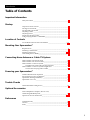
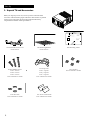
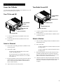
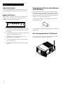
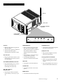
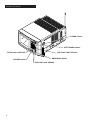
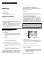
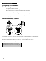
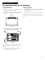
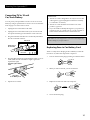
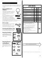
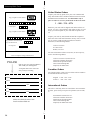
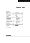
SPACEMAKERTM
Television/Radio User's Guide
GE LOGO
Model 05GP005
IMPORTANT INFORMATION
..........................................................i
TABLE OF CONTENTS
.........................................................1
STARTUP
.....................................................2-4
LOCATION OF CONTROLS
....................................................5-7
MOUNTING YOUR SPACEMAKERTM
.................................................8-10
CONNECTIONS
....................................................11
POWERING YOUR SPACEMAKERTM
..............................................12-15
TROUBLE CHECKS
...................................................16
OPTIONAL ACCESSORIES
.............................................17-18
REFERENCES
.............................................19-21
Safety Precautions
Important Information
WARNING
To prevent fire or shock
hazard, do not expose this
TV to rain or moisture.
WARNING
RISK OF ELECTRIC SHOCK
DO NOT OPEN
TO REDUCE THE RISK OF ELECTRIC SHOCK, DO
NOT REMOVE COVER (OR BACK). NO USER
SERVICEABLE PARTS INSIDE. REFER SERVICING
TO QUALIFIED SERVICE PERSONNEL.
This symbol indicates
“dangerous voltage” inside
the product that presents a
risk of electric shock or
personal injury.
This symbol indicates
important instructions
accompanying the
product.
To prevent electric shock, match wide blade of plug to wide
slot, fully insert.
Pour éviter les chocs électriques, introduire la lame la plus
large de la fiche dans la borne correspondante de la prise et
pousser jusqú au fond.
Cautions
Do not defeat the safety feature of the plug. The wide blade fits into the
wall socket only one way. If you need an extension cord, make sure it
matches the plug of the TV.
Operate TV only on 120 volts, 60 Hz AC power (normal house power) .
For safety reasons, make sure any equipment or accessories connected to
this product bears the UL listing mark or CSA certification mark. If in
doubt, contact qualified service personnel.
FCC Regulations state that unauthorized changes or modifications to this
equipment may void the user’s authority to operate it.
Note To Cable TV Installer
This reminder is provided to call your attention to Article 820-40 of the
National Electrical Code (Section 54 of the Canadian Electrical Code,
Part 1) which provides guidelines for proper grounding and, in particular,
specifies that the cable ground shall be connected to the grounding system
of the building as close to the point of cable entry as practical.
Product
Registration
Please fill out the product registration card and return it immediately.
Returning this card allows us to contact you if needed.
Keep your sales receipt to obtain warranty parts and service and for proof
of purchase. Attach it here and record the serial and model numbers in
case you ever need them. The numbers are located on the back of the TV.
05GP005
Model No.________________________________________________________
Serial No._________________________________________________________
Purchase Date: ___________________________________________________
Dealer/Address/Phone:____________________________________________
__________________________________________________________________
i
__________________________________________________________________
Introduction
Table of Contents
Important Information
Safety Precautions _____________________________________________________i
Startup
Unpack TV and Accessories ____________________________________________2
Turning TV On and Off ________________________________________________3
Turning Radio On and Off _____________________________________________3
Adjusting Volume ____________________________________________________4
Adjusting Picture _____________________________________________________4
Degaussing the Picture Tube ___________________________________________4
Using Carrying Handle as a Tilt Stand ___________________________________4
Location of Controls
TV and Radio Function and Control Buttons____________________________5 -7
Mounting Your Spacemaker™
Required Tools _______________________________________________________8
Mounting Considerations ______________________________________________8
Mounting Instructions ______________________________________________8-10
Unmounting the TV/Radio____________________________________________10
Connecting Home Antenna or Cable-TV System
Home Antenna with One Flat Lead _____________________________________11
Home Antenna with Two Flat Leads____________________________________11
Home Antenna or Cable TV System ____________________________________11
Using Round Coaxial Cable Carrying VHF Only ____________________11
Home Antenna or Cable TV System Using Round
Coaxial Cable Carrying VHF and UHF _____________________________11
Powering your Spacemaker™
Standard Household AC Operation ____________________________________12
DC Operation from Ten “D” Batteries ___________________________________13
Optional DC Rechargeable Battery _____________________________________14
Optional DC Car Cord ________________________________________________15
Trouble Checks
Check Here Before Calling Service______________________________________16
Optional Accessories
Stereo Headphone & Adapters, DC Car Cord,
and Rechargeable Battery Pack_________________________________________17
Optional Accessories Order Form____________________________________17-18
References
Limited Warranty ____________________________________________________19
Glossary ____________________________________________________________20
Index _______________________________________________________________21
1
Start Up
1. Unpack TV and Accessories
When you unpack your new TV, be sure you have removed all the
accessories and information papers. The items shown below are packed
with your TV. Some parts may have been packed in the battery
compartment in the back of the Spacemaker™.
Drill 1/4 inch holes at the 5
locations marked.
Percez trous de 1/4 pouce
aux 5 endroits indiques.
1/4"
3/4"
Screw Guide
Also cut out screw guide along
dashed lines to use for
checking proper screw lenght.
Decoupez aussi le guide de vissage
le long du pointille. Utilsez - le pour
verifier la longueur des vis.
Guide de montage pour
l'installation de TV
sous une armoire.
Guide de
vissage
*Note - For under-counter mounting, the supplied antenna must
be mounted to the bottom of the TV. Refer owner's manual
pages 6 and 26 for attachment instructions.
*Nota - Si vous installez la televiseur sous l'armoire, l'antenna
fournie doit etre montee a ia base du televiseur.
Voir les instructions de fixation dans le guide, aux
pages 6 et 26.
Mounting Guide for
mounting TV
under a cabinet.
Locate this edge 3/4 inch back from front edge of cabinet
if thickness of cabinet overhang exceeds 3/4 inch, locate
as close to front edge as possible.
Placez cette bordure a 3/4 pouce du devant de larmoire.
Si lepaisseur du surplomb de larmoire depasse 3/4 pouce,
placez la bordure aussi pres que possible du devant.
FRONT
Avant
One Detachable Power Cord
Stock #221151
One Mounting Bracket
Stock #221160
One Mounting Guide
Twelve Phillips Screws:
Four Washers
Part of #221160 or 195385
Four 3” Screws
Part of #221160 or 195385
Twelve Spacers
Four 1” Spacers
Four 1⁄2” Spacers
Four 1⁄4” Spacers
Part of #221160 or 195385
Four Hex Nuts
Part of #221160 or 195385
Two Power Cord Hooks
Part of #221160 or 195385
Twelve
Phillips
Four 1”
Screws Screws
Four1"
2” Screws
Four
Screws
2
Start Up
Power the TV/Radio
Turn Radio On and Off
You can power your Television/Radio several different ways. See
page 12 for the different power options.
Turn TV On and Off
OFF/TV/RADIO
Switch
TUNING Control
AM/FM Switch
OFF/TV/RADIO
Switch
AM Radio Dial Scale
TUNING Control
UHF/V-HI/V-LOW
Switch
VHF TV Dial Scale
FM Radio Dial Scale
A. To turn on, slide the OFF/TV/RADIO switch to the
RADIO position.
UHF TV Dial Scale
B.
A. To turn on, slide the OFF/TV/RADIO switch to the
TV position.
B.
To turn off, slide the OFF/TV/RADIO switch to the
OFF position.
Select a Channel:
To turn the radio off, slide the OFF/TV/RADIO switch
to the OFF position.
Select a Station:
A. Turn on radio by sliding the OFF/TV/RADIO switch to
the RADIO position.
B.
Select AM or FM.
A. Turn on the TV by sliding the OFF/TV/RADIO switch
to the TV position.
To select an AM station, slide the AM/FM switch to
the AM position.
B.
To select an FM station, slide the AM/FM switch to
the FM position.
Select UHF or VHF:
For UHF (14-69), slide the UHF/V-HI/V-LOW
switch to the UHF position.
For VHF channels (2-13), slide the UHF/V-HI/VLOW switch to V-HI for channels 7-13, or V-LOW
for channels 2-6.
C.
Rotate the TUNING control located on the side of the TV
until the indicator aligns with the channel you wish to
select on the TV dial scales (UHF for UHF channels or
VHF for VHF channels).
C.
Rotate the TUNING control located on the side of the
TV/Radio until the indicator in the radio dial scales
aligns with the radio station number you want to hear
(AM for AM stations or FM for FM stations).
D. Adjust the antenna for the best FM reception. The AM
antenna is built-in and somewhat directional. It may be
necessary to rotate the TV/Radio for the best AM
reception.
D. Adjust antenna to receive best picture.
3
Startup
Adjust the Volume
• Slide VOLUME to the right to increase the volume level.
• Slide VOLUME to the left to decrease the volume level.
Adjust the Picture
What is pleasing to one person may not be to another. If the
picture is not to your liking after you have tuned in a TV
channel, make the following adjustments:
HEADPHONE
CONTRAST BRIGHT COLOR
TINT
Degaussing the Picture Tube (Remove
Color Blotches)
Degaussing the picture tube removes any magnetic charge
build-up that has accumulated inside the TV due to electrical
devices such as appliances that may be operated nearby. Color
blotches or uneven color patches will appear in the TV picture
whenever your set needs to be degaussed.
Press the DEGAUSS button. Any magnetic build-up will be
immediately removed.
S
DEGAUSS EXT.ANT.
AUS
DEG
A. Turn COLOR and CONTRAST to the left as far as they
will go. This will leave a dim black and white image
on the screen.
Use this button sparingly during battery operation to minimize
battery drain.
B.
Turn BRIGHT left or right until portions of the picture
you know to be black appear black.
Use Carrying Handle as a Tilt Stand
C.
Turn CONTRAST to the right until the overall
brightness is to your preference.
Turn it under the TV as far as it will go. This allows you to tilt
the front of the TV for a better viewing angle.
D. Turn COLOR to the right until you reach a pleasing
level of color intensity.
E.
4
Adjust TINT until fleshtones and other colors appear
natural.
Location of Controls
Antenna
DC (12V) Jack
AC POWER (120V/60Hz)
Cord Jack
Carrying Handle
and Tilt Stand
HEADPHONE
CONTRAST BRIGHT COLOR
TINT
DEGAUSS EXT.ANT.
Antenna
DEGAUSS Button
CONTRAST Knob
• Receives UHF/VHF TV signals and
FM radio signals.
• Attach to the top clip for portable use.
• Attach to the bottom clip for
mounting the TV under the counter.
• Press to “degauss” the picture tube.
This removes any magnetic charge
build-up that may have accumulated
due to electrical devices such as
appliances that may be operated
nearby.
• Press whenever color blotches begin
to appear in the TV picture.
• Use sparingly during battery
operation to minimize battery drain.
• Controls the overall picture brightness
and contrast of the picture.
DC (12V) Jack
• Plug an optional DC 12-Volt car cord
into this jack to operate the TV from a
car/truck battery
Headphone Jack
• Plug optional headphones into this
jack for private listening.
Carrying Handle and Tilt Stand
• Folds out for portable use and folds
down for mounting the TV under a
cabinet.
TINT Knob
AC POWER (120V/60Hz) Cord Jack
• Plug the detachable power cord into
this jack for use with normal
household power (120 Volts)
EXT. ANT. (External
Antenna) Jack
• Use this jack to attach an external
home antenna (or cable TV) to your
TV.
• Controls the color of the fleshtones.
• The carrying handle can be used as a
tilt stand when folded under the TV.
COLOR Knob
• Controls the amount of color in the
picture.
BRIGHT Knob
• Controls the black level of the picture.
continued on next page
5
Location of Controls
TUNING Control
G
IN
NN
FU
NC
TIO
N
TU
S
US
GA
DE
T
TV
R
LO
-BA
ND
HT
UH
F
H
L
CO
IG
T
BR
AS
VH
TIN
OFF/TV/RADIO Switch
R
NT
F
CO
M
IN
RA
DIO
VO
-B
LU
AN
D
AM
ME
FM
MA
TV Dial Scales (UHF/VHF)
VOLUME Control
X
UHF/V-HI/V-LOW TV Switch
AM/FM Radio Switch
Radio Dial Scales (FM/AM)
6
Location of Controls
TUNING Control
• Turn to select the station or channel
after selecting TV or RADIO with the
OFF/TV/RADIO switch.
• Refer to the channel numbers on the
VHF/UHF dial scales when choosing
a TV channel.
• Refer to the station numbers on the
FM/AM dial scales when choosing a
radio station.
OFF/TV/RADIO Switch
• Place in the OFF position to turn off
the TV/Radio.
• Place in the TV position to select a TV
channel. Select UHF or VHF by first
placing the UHF/V-HI/V-LOW
switch in the proper position and then
turning the tuning control.
• Place in the RADIO position to select
a radio station. Select FM or AM by
first placing the AM/FM switch in the
proper position and then turning the
TUNING control.
UHF/V-HI/V-LOW/Switch
• Switch must be in the TV position to
select UHF and VHF television
channels.
• Place in the UHF position to select
UHF channels (14-69). Then slowly
rotate the TUNING control until the
indicator aligns with the desired
channel number on the UHF dial
scale.
• Place V-HI position to select VHF
channels 7 through 13, and in the VLOW position to select VHF channels
2 through 6. Then slowly turn the
TUNING control until the indicator
aligns with the channel on the VHF
dial scales.
AM/FM Radio Switch
• Place in the RADIO position to select
AM or FM radio stations.
• Set in the AM position to select AM
stations, and FM to select FM stations.
Then slowly turn the TUNING control
until the indicator aligns with the
number of the radio station under the
FM or AM radio dial scale.
Control Inside the
Battery Compartment
The FOCUS control in the battery
compartment is not a customer
control. It should only be adjusted
by a qualified service technician.
Radio Dial Scales (FM/AM)
• FM radio stations are listed under the
word FM, and AM stations are listed
under the word AM on the radio dial
scales.
VOLUME Control
• Slide to the right to increase volume.
• Slide to the left to decrease volume.
TV Dial Scales (UHF/VHF)
• UHF TV channel numbers are listed
under the UHF dial scale, and VHF
TV channel numbers are listed under
the VHF dial scale.
7
Mounting Your Spacemaker™
Follow the instructions below if you want to mount your
Spacemaker™ under a cabinet.
Required Tools
•
•
•
•
•
•
Ruler or Tape Measure
Masking Tape
Scissors
Phillips Screwdriver
Drill and 1⁄4” Drill Bit
Drill Countersink Attachment (Optional)
Mounting Considerations
• Make sure the bottom of the cabinet you select is strong enough
to hold the Spacemaker™.
• Allow adequate room on both sides of the Spacemaker™ to
allow proper ventilation and access to control knobs.
• Mount your Spacemaker™ near an AC power outlet so the
power cord will reach it.
• The area directly below your Spacemaker™ should not be used
for cooking or by appliances that generate heat or steam.
• Select an area as far away as possible from large metal appliances such as refrigerator, ovens, etc.
• Hold the Spacemaker™ in various locations while you think
through what will be the most convenient location in your
kitchen. Keep in mind your normal work pattern, especially
your use of other electrical countertop appliances.
• Before mounting, turn set on to check the AM radio reception
in the location you’ve selected.
Helpful Hints:
• You may want to start the drill holes with a nail or an awl.
• Splintering will be reduced if you place masking tape above the
hole locations on the inside of the cabinet.
• Be sure to hold the drill firmly against the cabinet to reduce
“walking” of the drill bit from the markings.
• If you have a countersink attachment for your drill and if you
are drilling through a wood cabinet, you may wish to countersink the drilled holes from the inside of the cabinet. This will
eliminate the use of washers and allow the screw heads to be
flush with the floor of your cabinet. If you cannot countersink
the holes, use the washers that are supplied.
CAUTION: Check thickness of shelf before attempting to
countersink holes. Minimum thickness should be at least 1⁄4”
( 3⁄8” or more preferred).
Mounting Your Spacemaker™
Mounting Instructions
1.
Prepare cabinet.
Cabinet
Cabinet
Overhang
A. To prevent anything from breaking, remove items from
the above the cabinet where the Spacemaker™ will be
mounted.
B.
2.
1-1/4″
Clean the underside of the cabinet to remove any
residue.
Cut out the Mounting Guide and Screw Guide,
4.
A. Cut out the guides on the lines indicated.
3.
B.
Position the Mounting Guide in the desired location and
tape it to the bottom of the cabinet. Be sure it is on a flat
surface free from any glue lumps or other bumps.
Note: Some kitchen cabinets have front overhangs as shown here.
If the thickness of the overhang exceeds 1-1⁄4 inches, tape the
Mounting Guide as close to the cabinet’s front edge as possible.
8
Drill holes in cabinet.
• Drill 1⁄4-inch diameter holes through the underside of the cabinet bottom using the four circles of the Mounting Guide as a
guide.
Position Mounting Guide on underside of cabinet.
A. Position the Mounting Guide on the underside of cabinet
at least 1-1⁄4 inches back from the cabinet’s front edge.
This will make the front of the TV almost flush with the
cabinet.
Mounting Guide
5.
Remove Mounting Guide and drill shavings.
Remove the Mounting Guide and clean the drill shavings from
inside and under the cabinet.
6.
Select spacers if required.
A. Spacers slip over the ends of the screws and allow you to
mount the TV below the edge of the cabinet’s overhang.
If your cabinet does not have an overhang, you probably
will not need to use any spacers.
If your cabinet has an overhang, select the proper length spacer(s)
so the bracket will clear the overhang
Mounting Your Spacemaker™
B.
Select spacers which are approximately 1⁄4” shorter than
the overhang. Two or three spacers can be used together
to make length of 1⁄4” to 1-3⁄4” at 1⁄4” increments.
C.
While holding the Bracket and selected spacers in place
under the cabinet, check to see that the Bracket clears the
overhang so the TV can be easily slid onto the Bracket or
removed for portable use.
8.
Position Mounting Bracket under cabinet as shown below
and match the screw holes.
Screw
Washer
7.
Select proper length of screws.
Spacer
A. Only four screws are needed. The size you need depends
upon your type of cabinet.
B.
C.
Spacer(s)
1/4”
5/8”
Screw
Guide
1/4” to 5/8” for
proper mounting
D. If the screw threads fall within the shaded area of the
Screw Guide, then the selected screw is of the proper
length for mounting the Bracket.
E.
Hex Nut
Holding the selected spacers for one of the screw holes
under the cabinet, install a washer and screw inside the
cabinet using one of the three lengths of screws provided.
Use the Screw Guide you cut from the Mounting Guide
to determine if the screw is the proper length for your
cabinet. (See the diagram below).
If the threads end above or below the shaded area, try
one of the other screws provided. (Screw length must fall
into the shaded area on the Screw Guide for proper
mounting).
Cabinet Bottom
Mounting Bracket
9.
Attach Mounting Bracket to cabinet.
A. First mount one corner of the Bracket. Hold the Bracket
and spacer(s) in place and insert the screw from the
inside of the cabinet down through washer and drilled
hole or down through countersink and drilled hole.
Note: The washers must be used on metal cabinets and on wood
cabinets if you did not countersink the drilled holes.
B.
Position the washer flat-side down and place screw into
screw hole, through the spacer(s), and through the screw
hole in the Mounting Bracket.
C.
Place a nut into the cylinder at the bottom of the
Mounting Bracket screw hole. Hold nut in place (if necessary, use the top of a pencil). While maintaining upward
pressure on the Mounting Bracket, finger tighten the
screw. Do not tighten firmly until all four screws have
been started.
D. Align each of the remaining three Mounting Bracket
screw holes with the drilled holes and properly position
the selected spacers. Install washers, screws, and nuts as
previously described. Now, finish tightening the four
screws but do not over-tighten them.
CAUTION: If the screw is too short, it will not screw into
the nut far enough to securely hold the TV. If the screw is
too long, it may protrude below the Bracket, and the TV
will hit it when sliding onto the Bracket.
Note: If none of the screws provided are the proper length for
your cabinet, you can do one of the following:
a) Increase the spacer length by 1⁄4” and try one of the longer
screws provided.
b) Purchase proper length screws at your local hardware
store (type #10-32).
9
Mounting Your Spacemaker™
10. Clip dipole antenna to bottom clip.
A. If the dipole antenna is attached to the top clip, remove it
from the clip, and rotate it to the bottom.
B.
Snap the antenna into the bottom clip.
Top Clip
TUNING
Retaining Rail
HEADPHONE
CONTRAST BRIGHT COLOR
TINT
DEGAUSS EXT.ANT.
Bottom Clip
12. Attach AC Power Cord.
A. First attach the AC Power Cord to the plug on the side of
the TV marked AC POWER (120V/60Hz).
11. Slide Spacemaker™ onto Bracket.
A. Slide the Spacemaker™ onto the retainer rails of the
Bracket until the front of the TV is approximately flush
with the front edge of the cabinet.
As you slide the TV back, it will stop at each of four locking positions. To unlock and move further back, lift the TV upward to
release it while continuing to slide it back. If more clearance is
required between the back of the unit and the kitchen wall, slide
the unit forward to one of the other locking positions.
B.
Then extend the cord and plug it into an electrical outlet.
13. Attach Cord Hooks.
You can use the Cord Hooks to hold the cord out of the way.
A. Place the Cord Hooks at the back edge of the cabinet (on
or next to the wall) directly above the outlet to be used.
B.
Peel off the adhesive back and attach the hooks to a
clean, dry surface on underside of cabinet or back wall.
CAUTION: Do not leave the unit in the Bracket forward of the first
locking position.
AC Power
Cord
Unmounting Your Television/Radio
While lifting the TV/Radio up, gently pull it toward you.
Gently pull
Lift up
10
Cord
Hooks
Electrical
Outlet
Connecting Home Antenna or Cable-TV Systems
Follow one of these steps to connect a home antenna or cable-TV system to your TV.
A. Home Antenna
If the cable coming from your antenna is a flat twin-lead cable that carries VHF and/or UHF signals,
connect it to your set like this:
From Home
Antenna
EXT. ANT.
Antenna Adapter*
(such as #195400)
VHF and/or UHF
Insert Plug In TV’s
Jack Labeled EXT. ANT.
B. Home Antenna
If your antenna has two separate flat twin-lead (one for VHF and one for UHF signals), connect it to
your set like this:
From Home
Antenna
EXT. ANT.
UHF
VHF
Insert Plug In TV’s
Jack Labeled EXT. ANT.
Adapter*
(such as RCA #AH058)
C. Home Antenna or Cable-TV System
If the cable coming from your antenna or cable-TV system is a round coaxial cable that carries only VHF signals, connect it to your set like this:
EXT. ANT.
From Home Antenna
or Cable-TV System
VHF or Cable
Insert Plug In TV’s
Jack Labeled EXT. ANT.
Antenna Adapter*
(such as RCA #189268)
D. Home Antenna
If the cable coming from your antenna is a round coaxial cable that carries both VHF and UHF signals,
connect it to your set like this:
EXT. ANT.
From Home
Antenna
VHF and UHF
Insert Plug In TV’s
Jack Labeled EXT. ANT.
Antenna Adapter*
(such as RCA #189268)
*Optional accessory available from your local GE dealer or electronic supply store
11
Powering Your Spacemaker™
You can power your Spacemaker™
four different ways:
A. Standard Household AC Operation.
Plug the power cord into a standard AC power outlet.
B.
DC Operation from ten “D” batteries installed in the battery compartment.
C.
Optional DC Rechargeable Battery.
You can purchase an optional rechargeable battery to install in the battery compartment.
D. Optional DC Card Cord.
You can purchase an optional DC car cord and operate your Spacemaker™ from the
cigarette lighter of a car or truck.
Standard Household AC Operation.
1st
Side of TV
2nd
AC POWER
120V 60Hz
–
DC 12V
c
+
Insert Plug
Completely
Your Spacemaker™ is designed to operate from standard polarized AC household outlets having 120-Volt, 60-Hz current.
1.
Insert the flat end of the detachable power cord in the AC POWER (120V/60Hz) jack located on the side on the TV.
Note: The plug will fit into the jack only one way. If it does not fit, turn it over and insert it the other way.
2.
Plug the other end of the AC cord into a polarized AC outlet.
CAUTION: To prevent electric shock, do not use the polarized
plug on this TV with an extension cord, receptacle, or other outlet
unless both blades can be fully inserted to prevent blade exposure.
12
Powering Your Spacemaker™
DC Operation from Ten “D” Batteries
Installing Batteries
Battery Operation
You can operate your Spacemaker™ from DC power by installing
ten “D” batteries into the battery compartment.
• Make sure the detachable AC power cord is removed from the
AC POWER jack. The TV will not operate on battery power if
the cord is attached.
1.
• Replace the batteries if TV picture shrinks or becomes unstable.
Remove the cover of the battery compartment located on the
back of the TV by pressing down on the two tabs marked
OPEN.
Press Here
OPEN
Note: Remove the batteries from the unit if they are not going to
be used for a long time because leakage could occur and corrode
the unit.
OPEN
Back of TV
2.
Insert ten “D” batteries into the battery compartment as indicated by the drawings in the battery compartment. Be sure to
insert a battery in the single battery compartment.
Single
Battery
Compartment
Negative
(–) Terminals
Positive
(+) Terminals
–
+
–
+
–
+
Battery Compartment
Back of TV
Note: Alkaline batteries are recommended and will provide
more hours of operation. They will also reduce the possibility
of leakage.
3.
Replace the battery cover by inserting the bottom tabs into
their slots and snapping the cover into place.
13
Powering Your Spacemaker™
Optional Rechargeable Battery
Operating Instructions
The rechargeable battery (No. RT007) is an optional accessory
available from your local GE dealer. You can also use the order
form on page 17 to order a battery. When fully charged, the battery will supply about 2 to 2-1⁄2 hours of operating time.
Be sure to recharge the battery before and after use.
1.
Unplug the TV’s power cord from the wall outlet and completely remove the cord from the AC POWER jack on
the side of the TV.
Charging Instructions
2.
Open the battery compartment cover on the back of the TV.
Press down on the two top tabs and gently remove the cover.
3.
Insert the battery into the compartment with the negative (-)
contacts to the left and the positive (+) contacts to the right as
shown inside the TV. Your TV may be damaged if the battery
is not properly connected.
4.
Replace the battery compartment cover by first inserting the
bottom two tabs and then gently pressing the cover closed at
the top.
5.
Operate your TV or radio as normal.
• The battery is initially fully charged. However the battery may
not give full operating time with it’s initial use.
• To recharge the battery, use the charger that came packed with
the battery.
1.
Connect the 2-wire plug from the charger to the matching
connector on the battery. This connection has been designed
so that connection can only be made one way.
2.
Plug the charger into any 120-volt AC wall outlet and the battery will begin its recharge cycle. The battery should be
recharged for 24 hours after each use.
Notes:
• Your rechargeable battery can be used with as little as 18 hours
of daily recharging for a limited period, up to two weeks. After
such use, it is recommended that you recharge the battery for
48 hours, to maintain maximum play time and battery life.
• For maximum battery life, start recharging the battery within
24 hours of each use. Disconnect the battery from the charger
after 48 hours because additional charging wastes energy and
may shorten battery life.
PRECAUTIONS
• To prevent damage which may result in fire or shock hazard, do not operate the television set on battery power
while recharging the battery.
• Avoid charging the battery in temperature over 104° F.
This will reduce the battery life.
• Be sure to recharge the battery before and after use. If left
uncharged for a long period of time, the battery will be
excessively discharged resulting in a shorter life.
• Never store battery in temperatures above 100° F or in
direct strong sunlight.
• Do not short circuit battery.
• Do not place battery in fire.
14
CAUTION: When the TV picture shrinks approximately 1⁄4
inch on each side, the battery is discharged. Continued use of
the battery without recharging will damage it. Remove the
battery from the TV and recharge it according to the
instructions at the left.
Powering Your Spacemaker™
Connecting TV to 12-volt
Car/Truck Battery
IMPORTANT
• The DC Car Cord is designed for use only in cars or trucks
with negative (-) ground (negative terminal of car battery
is connected to car chassis).
You can power your Spacemaker™ from a 12-volt car or truck
battery by using an optional DC Car Cord. You can use the order
form on page 17 to order a DC Car Cord.
1.
Unplug the AC cord from the wall outlet.
2.
Unplug the AC cord from the side of your TV. The TV will
not operate on battery power unless this cord is removed.
3.
Plug the small end of the DC Car Cord into the jack labeled
DC 12V on the side of the TV.
• The DC Car Cord should never be used in cars with a
positive (+) ground.
• If you are unable to identify the negative (-) or positive (+)
polarity of your car, consult your car’s owner’s manual or
check with an authorized service station before use.
CAUTION: Use of an improper DC Car Cord or similar adapter may
result in damage to your Spacemaker™.
Side of TV
Small Plug on
DC Car Cord
Replacing Fuse in Car Battery Cord
AC POWER
120V 60Hz
4.
–
DC 12V
c
+
Plug the other end into the cigarette lighter socket of a car or
truck. (Make sure the vehicle has a negative ground as
explained at right).
There is a safety fuse in the plug of the Car Battery Cord. If the
fuse blows out, follow the steps below to replace it.
1.
Unscrew the end of the plug by turning it counterclockwise.
2.
When you remove the end, you will see the fuse.
3.
Replace fuse with a new 250-volt, 3-amp fuse.
4.
Screw end back on plug.
Cigarette Lighter Socket
in Car
Large Plug
on Car Battery Cord
5.
Operate TV as normal.
15
Trouble Checks
You may have problems that can be fixed with a few minor adjustments. Look for the type of problem you are having below and then
try the suggestions to get your TV going again. For warranty information see page 19.
Trouble
Check
No picture or sound.
(AC power)
•
•
•
•
No Picture or sound
(battery operation).
•
•
•
•
•
Sound OK; poor picture.
•
•
•
Picture OK; poor sound.
•
•
•
Poor reception.
•
•
•
Lines in picture.
•
•
•
Picture rolls vertically.
•
•
No color or poor color.
•
•
•
•
Ghosts (multiple images).
•
•
Adjust
Be sure power cord is plugged in.
Be sure TV is turned on.
Try another channel (station trouble).
Check antenna connections.
Be sure TV is turned on.
AC power cord must be removed from TV.
Maybe batteries are weak.
Maybe battery pack is weak.
Check antenna connections.
•
•
•
•
Remove AC power cord.
Install new batteries.
Recharge battery pack.
Adjust dipole antenna.
Try another channel (station trouble)
Check antenna connection.
May be local interference.
•
Try another channel (station trouble).
Check antenna position.
May be local interference.
•
•
Adjust VOLUME.
Adjust dipole antenna.
Try another channel (station trouble).
Check antenna position.
May be local interference.
•
Adjust dipole antenna.
Try another channel (station trouble).
Check antenna position.
May be local interference.
•
Adjust dipole antenna.
Try another channel (station trouble).
Check antenna position.
May be local interference.
May be batteries are weak.
•
Adjust dipole antenna.
Adjust TINT and COLOR knobs.
Install new batteries or recharge
battery pack.
Try another channel (station trouble).
Check antenna position.
•
•
•
Adjust BRIGHT knob.
Adjust CONTRAST knob.
Adjust antenna.
Try another channel (station trouble).
May be local interference.
•
•
•
Adjust dipole antenna.
May be local interference.
Color blotches in picture.
•
Press DEGAUSS button to remove magnetic build
up from picture tube.
Blurry picture.
•
Check antenna position.
•
Try moving antenna.
Background noise, interference.
•
•
Try another channel (station trouble).
Check antenna position.
•
Try moving antenna.
Poor FM reception
•
Check antenna position.
•
Adjust dipole antenna.
Poor AM reception
•
Built-in directional AM antenna not
aimed for best reception.
•
Turn Spacemaker™ around
16
Cut Here
✄
Optional Accessories
Your Television/Radio is highly versatile piece of equipment. The
accessories shown below will let you take full advantage of that
versatility.
Order Form for
Model 05GP005
Stereo Headphone &
Adapters
Lightweight stereo headphone with 3.5mm
stereo plug. Includes the two Headphone
Adapters shown below at no extra cost.
No. 3-5750
Description
Model
No.
Price
Each*
Qty
Total
Amount
Fuse for DC Power Cord
175857
$ 3.15
Antenna Adapter
189268
$12.75
Mounting Hardware
195385
$15.75
and Hardware
221160
$28.45
Antenna Adapter
195400
$ 7.25
Stereo Headphone and
Adapters
3-5750
$17.95
Antenna Adapter
AH058
$ 9.95
DC Car Cord
221162
$13.95
Rechargeable Battery Pack
RT007
$83.95
Replacement Power Cord
221151
$11.45
Total Merchandise ($10 minimum order) ................
Sales Tax
........................................................
$ _____
$ _____
Mounting Bracket
The 1/4-inch adapter allows you to use the
headphone shown above with stereo
products that have a 1⁄4” headphone jack.
1/4" Stereo Adapter
The 3.5 adapter lets you use the headphone
3.5 mm Mono Adapter
shown above with mono products that have a
3.5mm headphone jack. These adapters automatically come with
the Stereo Headphone shown above at no extra cost.
DC Car Cord
*Prices are subject to change without notice
This Car Cord plugs into a cigarette lighter
and allows you to power your
Television/Radio from a car or truck. Keep
one in each of your vehicles. No. 221162
We are required by law to collect the appropriate
sales tax for each individual state, county, and
locality to which the merchandise is being sent.
Shipping, Handling, and Insurance...........................
Total Amount Enclosed ...............................................
Rechargeable Battery Pack
Powers your Television/Radio for about 2 to
2-1⁄2 hours when fully charged. No. RT007
$ 5.00_
$ _____
VISA or MasterCard Preferred.
Money order or check must be in US currency only.
No COD or CASH.
Mounting Hardware
Four Hex Nuts
Four Washers
Twelve Spacers:
Four 1" Spacers
Four 1/2" Spacers
Four 1/4" Spacers
Twelve Phillips Screws:
Four 1" Screws
Four 2" Screws
Four 3" Screws
Mounting Bracket
and Hardware
Two Power Cord Hooks
Drill 1/4 inch holes at the 5
locations marked.
Percez trous de 1/4 pouce
aux 5 endroits indiques.
1/4"
3/4"
Screw Guide
Also cut out screw guide along
dashed lines to use for
checking proper screw lenght.
Decoupez aussi le guide de vissage
le long du pointille. Utilsez - le pour
verifier la longueur des vis.
*Note - For under-counter mounting, the supplied antenna must
be mounted to the bottom of the TV. Refer owner's manual
pages 6 and 26 for attachment instructions.
*Nota - Si vous installez la televiseur sous l'armoire, l'antenna
fournie doit etre montee a ia base du televiseur.
Voir les instructions de fixation dans le guide, aux
pages 6 et 26.
Locate this edge 3/4 inch back from front edge of cabinet
if thickness of cabinet overhang exceeds 3/4 inch, locate
as close to front edge as possible.
Placez cette bordure a 3/4 pouce du devant de larmoire.
Si lepaisseur du surplomb de larmoire depasse 3/4 pouce,
placez la bordure aussi pres que possible du devant.
Please Complete Other Side Also
FRONT
Avant
One Mounting Bracket
One Mounting Guide (Template)
Four Washers
Twelve Phillips Screws:
Four 1" Screws
Four 2" Screws
Four 3" Screws
Four Hex Nuts
Twelve Spacers:
Four 1" Spacers
Four 1/2" Spacers
Four 1/4" Spacers
Specifications and descriptions of accessories are subject to change without notice.
Cut Here
The Mounting Bracket and
Hardware allow you to mount
your TV/Radio under a cabinet.
Mounting Guide for
mounting TV
under a cabinet.
Guide de montage pour
l'installation de TV
sous une armoire.
Guide de
vissage
Two Power Cord Hooks
✄
The Mounting Hardware are the
hardware pieces only that are
needed to mount your TV/Radio
under a cabinet.
17
Cut Here
✄
Accessory Order Form
United States Orders
USE YOUR CREDIT CARD
To place your order by phone, have your Visa or MasterCard
ready and call the toll-free number listed below between 8AM
and 8PM Eastern Standard Time. Use this number only to
place an order for accessory items listed on this order form.
®
Copy complete account number
1 – 800 – 338 – 0376
Card expires:
s r
Copy complete account number
r
Most time your order will be shipped UPS within 72 hours of
receipt. If ever it is not possible to ship within 30 days, we will
notify you with an update on your order and an option to cancel.
TM
To place your order by mail, detach and mail the completed
order form with credit card information, money order, or check
in U.S. currency (made payable to Thomson Consumer
Electronics) to the following address:
Copy Number above the name
on your MasterCard
Video Accessories
P.O. Box 8419
Ronks, PA 17573
Card expires:
AUTHORIZED SIGNATURE
For more information on these accessories (or current prices),
write to the following address:
Prices are subject to change without notice.
Video Accessories Customer Service
Thomson Consumer Electronics
Distributor & Special Products
2000 Clements Bridge Rd
Deptford, NJ 08096-2088
PLEASE
Print or type your name and address.
This will be your mailing label.
A complete and correct order will
save you days of waiting.
Canadian Orders
For Canada inquiries, please call one of these toll-free numbers
for information about accessories:
Name:
English: 1 – 800 – 668 – 5518
French: 1 – 800 – 668 – 5507
Street:
Apt:
International Orders
City:
State:
This offer is valid only in the 50 United States. For international orders, please send your request for quotation (not an order)
to:
Zip:
International Customer Service
Thomson Consumer Electronics
Distributor & Special Products
2000 Clements Bridge Rd
Deptford, NJ 08096-2088 USA
18
✄
Cut Here
Make sure that both sides of this
form have been filled out.
Limited Warranty
Spacemaker™ Color Television/Radio
What your Warranty covers:
• Any defect in material or workmanship.
For how long after your purchase:
• 90 days for labor charges.
• One year for parts.
• Two years for picture tube.
The warranty period for rental units begins with the first rental.
What we will do:
• Pay any Authorized GE Television Service center the labor charges to repair your television.
• Pay any Authorized GE Television Service center for the new or, at our option, rebuilt replacement
parts and picture tube required to repair your television.
How you get service:
• Take your television to the Authorized GE Television Service center of your choice. To identify
your nearest Authorized GE Television Service center, ask your Dealer, look in the Yellow Pages,
or call 1-800-447-1700.
• Show the Authorized Service center Representative your sales receipt or other evidence of purchase date.
• Pick up your television when repairs are completed.
What your warranty does not cover:
• Customer instruction. (Your Owner’s Manual clearly describes how to install, adjust, and operate
your television. Any additional information should be obtained from your Dealer).
• Installation and related adjustments.
• Signal reception problems not cause by your television.
• Damage from misuse or neglect.
• Batteries.
• A television that has been modified or incorporated into other products or is used for institutional
or other commercial purposes.
• Customer-replaceable fuses.
• A television purchased or serviced outside the USA
How state law relates to this warranty:
• This warranty gives you specific legal rights, and you also may have other rights that vary from
state to state.
If you purchased your television in Canada:
• The Canadian Warranty applies in place of this Warranty.
19
References
Glossary
AC Operation (120 volts, 60 Hz)
Dipole Antenna
UHF/V-Hi/V-Low Switch
Normal household power available at wall
outlet.
Adjustable antenna on TV. Receives
UHF/VHF TV and FM radio signals. See
Antenna.
Switch used to select UHF or VHF television stations. UHF for channels above 13,
V-Hi for channels 7 through 13 and V-Low
for channels 2 through 6.
AC Power Cord Jack
Detachable power cord that connects normal household power to your TV.
Ext. Ant. Jack (External Antenna)
Jack (port) on TV used to connect an external home antenna or cable TV to your TV.
AC Power Plug
Detachable power cord that connects normal household power to your TV.
FM Antenna
AM Antenna
Image Imprint
Directional antenna built-in TV for receiving Am radio signals.
Ghost images on TV screen caused by
improper use of TV with some video
games.
See Antenna.
AM/FM Radio Switch
Switch used to select AM or FM radio station broadcasts.
Monaural
Sound system with only one audio channel output.
Antenna
A device used to receive broadcast signals
form local TV and radio stations. Receives
UHF/VHF TV signals and FM radio signals.
Mono
Slang for monaural.
Radio Dial Scales
See AM/FM Radio Switch.
Awl
Pointed tool used to start the drill holes
for mounting your TV.
Bright (Brightness)
Knob controlling black level (light and
dark areas) of TV picture.
Rechargeable Battery Pack
Optional accessory that provides 12-volt
DC power for portable Radio/TV operation. Rechargeable from standard household 120-volt AC wall outlet.
Stereo
See DC Car Cord
Two-channel sound system using separate
right and left channels.
Contrast
Stereo Headphone
Knob controlling overall brightness and
contrast of TV picture.
Accessory providing two-channel sound.
Car Battery Cord
Tint
DC Car Cord
Color in fleshtones on TV picture.
Optional 12 volt DC power cord for operating TV/Radio from car/truck battery.
Tuning Control
DC Operation (12 volt)
Dial control for fine tuning on radio and
TV stations.
Power supplied by ten “D” cell batteries
or optional DC 12-volt power cord
plugged into cigarette lighter of car/truck.
20
UHF
Abbreviation for channels transmitting
Ultra High Frequency TV signals (above
channel 13).
VHF
Abbreviation for channels transmitting
Very High Frequency TV signals (channels 2 - 13).
References
Index
AC operation ..............................11, 20
AC power cord ...........................10, 20
AC POWER (120V/60Hz)
cord jack .....................5, 12, 14, 20
Accessories....................................2, 17
AM antenna ......................................20
AM/FM radio switch ..............6, 7, 20
AM selection .......................................3
Antenna .........................................5, 20
Antenna adapter ..............................11
Antenna connections .......................11
Awl.....................................................20
Batteries .................................13, 14, 17
Battery operation ........................13-15
Battery pack ..........................14, 17, 20
BRIGHT knob ...........................4, 5, 20
Cable-TV connections......................11
Car/truck battery operation...........15
Channel selection ...............................3
Cigarette lighter socket for
battery connection ....................15
Color blotches removal .....................4
COLOR knob ..................................4, 5
CONTRAST knob ....................4, 5, 20
DC car cord ...........................15, 17, 20
DC operation (12 volt)...............13, 20
DC (12V) jack......................................5
DEGAUSS button...........................4, 5
Degaussing picture tube ...................4
Dipole antenna .................................20
EXT. ANT. (external
antenna) jack....................5, 11, 20
FM selection........................................3
FOCUS control ...................................6
Fuse in car battery cord...................15
Handle and tilt stand.....................4, 5
Headphone adapters .......................17
Headphone jack..................................5
Headphones......................................17
Home antenna connections ............11
Image imprint...................................20
Monaural...........................................20
Mounting TV/radio .....................8-10
OFF/TV/RADIO switch...........3, 6, 7
Picture adjustment.............................4
Picture tube, degaussing...................4
Powering TV/radio....................12-15
Radio, turning on and off .................3
Radio dial scales (FM/AM)....6, 7, 20
Rechargeable battery pack..14, 17, 20
Station selection .................................3
Stereo .................................................20
Stereo headphones.....................17, 20
TINT knob.................................4, 5, 20
Tools required for mounting............8
Trouble shooting ..............................16
TUNING control ..................3, 6, 7, 20
Turning radio on and off ..................3
Turning TV on and off ......................3
TV, turning on and off ......................3
TV dial scales (UHF/VHF)...........6, 7
UHF....................................................20
UHF connections..............................11
UHF selection .....................................3
UHF/V-Hi/V-LOW/
switch .............................3, 6, 7, 20
Unpacking TV ....................................2
VHF........................................................
20
VHF connections..............................11
VHF selection .....................................3
VOLUME control .......................4, 6, 7
Warranty ...........................................19
21
If your TV needs service, please contact your
dealer or the nearest servicenter. Please do
not send any products to the Indianapolis
address listed below or on the box. This only
adds delays for service of your TV. See how
to get service in the warranty on page 19.
Thomson Consumer Electronics
600 N Sherman Dr, PO Box 1976
Indianapolis, IN 46206-1976
©1994 Thomson Consumer Electronics, Inc.
Trademarks(s)® Registered
Marca(s) Registrada(s)
Printed in U.S.A.
Part Number 1Q57 441-01A