1
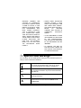
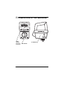
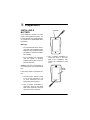
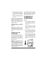
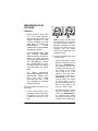
Please read before using this equipment.
Owner’s Manual
Clamp-On AC Ammeter
with Detachable Multimeter
ˆ Contents
Features ........................................................................................................... 3
A Word About Safety .................................................................................. 4
Special Panel Markings .................................................................................. 5
Specifications ..................................................................................................
Ranges .......................................................................................................
Accuracy ....................................................................................................
Miscellaneous ............................................................................................
6
6
6
6
A Quick Look at Your Multimeter ................................................................... 7
Preparation ...................................................................................................... 8
Installing a Battery ...................................................................................... 8
Connecting the Test Leads ......................................................................... 9
Connecting the AC Ammeter to the Multimeter .......................................... 9
Zero Adjustment ....................................................................................... 10
Using the Multimeter .....................................................................................
Making Measurements .............................................................................
Measuring DC/AC Voltage .......................................................................
Measuring Three-Phase AC Voltage ................................................
Measuring AC Voltage Riding on a DC Source Bias ........................
Measuring Current ...................................................................................
Measuring DC Current ......................................................................
Measuring AC Current in a Wire .......................................................
Measuring Wattage ..................................................................................
Measuring Resistance ..............................................................................
10
10
11
12
13
13
13
14
16
16
Care ................................................................................................................ 17
Cleaning ................................................................................................... 17
Replacing the Fuse .................................................................................. 18
© 2001 RadioShack Corporation.
All Rights Reserved.
RadioShack and RadioShack.com are trademarks used by RadioShack Corporation.
2
Contents
ˆ Features
Your RadioShack Clamp-On AC Ammeter with Detachable Multimeter is
designed with a precision meter
movement to avoid mechanical shock
damage. Your portable, compact multimeter is ideal for field, lab, shop,
bench, and home applications. The
multimeter measures DC and AC current, DC and AC voltage, and resistance.
Important:
• This multimeter is designed for
indoor use only.
• Completely read this manual
before you use the multimeter.
• If you are not familiar with multimeters and testing procedures,
we suggest you read the book
Using Your Meter (available at
your local RadioShack store)
before you use this multimeter.
Here are some features that make
your multimeter a real pro:
Fuse and Diode Protection — help
protect the multimeter.
Battery Condition Testing — the
multimeter shows when you need to
replace the battery.
Detachable Test Leads — let you
store the multimeter neatly and connect the test leads only when you
need to use the multimeter.
Deluxe Carrying Case — protects
your multimeter, ammeter, and test
leads and lets you take them almost
anywhere.
Your multimeter has passed the critical safety tests required by Underwriters Laboratories for test equipment,
meets UL 3111 Installation Category
1, Pollution Degree 2, and its 2000
ohm/volt sensitivity ensures accurate
readings.
Note: Your multimeter requires one
AAA battery (not supplied).
Detachable Clamp-On AC Ammeter
— lets you measure AC current by
simply clamping around a wire quickly
and safely.
Hold Function — lets you easily hold
the displayed value when measuring
AC current, so you can see the reading even after you disconnect the ammeter.
Features
3
A WORD ABOUT
SAFETY
cover is in place and fully closed
with the screw fully tightened.
We have taken every precaution in
designing this multimeter to ensure
that it is as safe as we can make it.
But safe operation depends on you,
the operator. We recommend that
you follow these simple safety rules:
• Never apply voltages to the multimeter that exceed the limits
given in “Specifications” on
Page 6. Never apply more than
500V DC or 500V RMS AC
between any input terminals or
between an input terminal and
ground.
• Because many AC/DC sets have
a potentially hot chassis, be sure
the top of your workbench and
the floor underneath it are made
of non-conductive materials.
This multimeter is fully calibrated and
tested. Under normal use, no further
adjustment should be necessary except as noted in this Owner’s Manual.
If the multimeter requires repair, do
not try to adjust it yourself. Take it to
your local RadioShack store.
WARNINGS:
• Always discharge any capacitors
of the circuit under test before
you attach test leads.
• USE EXTREME CAUTION IN
THE USE OF THIS DEVICE.
IMPROPER USE OF THIS
DEVICE CAN RESULT IN
INJURY OR DEATH. FOLLOW
ALL
SAFEGUARDS
SUGGESTED IN THIS OWNER’S
MANUAL IN ADDITION TO
NORMAL SAFETY PRECAUTIONS IN DEALING WITH
ELECTRICAL CIRCUITS. DO
NOT USE THIS DEVICE IF YOU
ARE UNFAMILIAR WITH ELECTRICAL CIRCUITS AND TESTING PROCEDURES.
• Always turn off power and disconnect the test leads from the
circuit you are testing before you
replace the multimeter’s battery.
• NEVER TRY TO PROBE WITH
BOTH TEST LEADS AT THE
SAME TIME OR HOLD BOTH
TEST LEADS IN ONE HAND.
• Never operate the multimeter
unless its battery compartment
• USE EXTREME CARE WHILE
USING THE MULTIMETER TO
• Use extreme caution when working with voltages above 40V.
Always disconnect power from
the circuit you are measuring
before you connect test leads to
high-voltage points.
• Never connect the test leads to a
source of voltage when the function selector is set to R×1KΩ,
R×100Ω, 150mA DC mA, or ACA.
4
Features
MEASURE CURRENT AND
VOLTAGE IN COMMERCIAL
ELECTRICAL PANELS. UNLIKE
A HOME AC OUTLET, A COMMERCIAL ELECTRICAL PANEL
HAS
TREMENDOUS
CURRENT SURGE POTENTIAL.
THIS IS ESPECIALLY TRUE
FOR THREE-PHASE INDUSTRIAL ELECTRICAL PANELS. A
SMALL SPARK FROM ONE OF
THESE PANELS CAN CAUSE A
PLASMA EXPLOSION AND
FIRE THAT CAN SEVERELY
BURN YOU. DO NOT HOLD
THE
MULTIMETER
WHILE
USING IT.
• ALWAYS WEAR PROTECTIVE
LEATHER GLOVES, A FACE
SHIELD, AND FIREPROOF ARM
AND UPPER BODY PROTECTION WHILE USING THE MULTIMETER
TO
MEASURE
CURRENT AND VOLTAGE IN
COMMERCIAL
ELECTRICAL
PANELS.
• IF THIS EQUIPMENT IS USED
IN A MANNER NOT SPECIFIED
BY THE MANUFACTURER,
THE PROTECTION PROVIDED
BY THE EQUIPMENT MAY BE
IMPAIRED.
• TO REDUCE THE RISK OF
FIRE OR SHOCK HAZARD, DO
NOT EXPOSE THIS PRODUCT
TO RAIN OR MOISTURE.
ˆ Special Panel Markings
For your safety, we have added special markings to the multimeter’s panel to remind you of the measurement limitations.
500V
MAX
To avoid electrical shock or damage to the multimeter, do
not connect the ground terminal (– jack) to any source
that exceeds 500 volts with respect to earth/ground.
500V
RMS
MAX
To avoid electrical shock or damage to the multimeter, do
not connect the test leads to any source that exceeds 500
volts RMS AC.
!
Caution: Risk of electric shock! Refer to the complete
operating instructions.
Caution: Be extra careful when making high-voltage
measurements; DO NOT TOUCH TERMINALS OR
PROBE ENDS.
Special Panel Markings
5
ˆ Specifications
RANGES
AC/DC Voltage .......................................................................... 15V, 150V, 500V
DC Current .............................................................................................. 150 mA
AC Current ..................................................................................... 3A, 15A, 30A
Resistance ...................................................................... 100kΩ (Center 3.5KΩ),
10KΩ (Center 350Ω)
ACCURACY
DC .......................................................................................... ±3.0% of full scale
AC .......................................................................................... ±4.0% of full scale
Resistance ................................................................... ±3.0% at full scale length
Sensitivity, AC/DC Voltage ............................................................... 2000 Ω/Volt
MISCELLANEOUS
Operating Temperature ............................................... 32 to 109.4°F (0 to 43°C)
Storage Temperature .................................................. –4 to 140°F (–20 to 60°C)
Power Source ........................................................................... One AAA battery
Dimensions (HWD) .......................................................... 77/8 × 25/8 × 11/8 Inches
(200 × 66 × 28 mm)
Weight ........................................................................................... 8.8 oz (250 g)
Included Accessories .......................................................................... Test leads
AC Ammeter
Carrying Case
Specifications are typical; individual units might vary. Specifications are subject
to change and improvement without notice.
6
Specifications
ˆ A Quick Look at Your Multimeter
OHM
S
Ω
OHMS
ADJUST
(left side of
multimeter)
AC AMMETER
MULTIMETER
A Quick Look at Your Multimeter
7
ˆ Preparation
INSTALLING A
BATTERY
Top Cover
Your multimeter requires one AAA
battery (not supplied) for power. For
the best performance and longest life,
we recommend a RadioShack alkaline battery.
Warnings:
• To avoid electrical shock, disconnect both of the multimeter’s test
leads from any equipment before
you install or remove the multimeter’s battery.
• Do not operate your multimeter
until the battery is properly
installed and the back cover is in
place and secured.
3. Use a Phillips screwdriver to
remove the screw on the lower
back of the multimeter, then
remove the multimeter’s back
cover.
Caution: Use only a fresh battery of
the required size and recommended
type.
Follow these steps to install the battery.
1. Set the function selector to OFF
to turn off the multimeter if it is
on, then disconnect the test
leads if they are connected.
2. Use a Phillips screwdriver to
remove the screw on the upper
back of the multimeter. Then pull
up the top cover to remove it.
8
Preparation
Back
Cover
4. Place the battery in the compartment as indicated by the polarity
symbols (+ and –) marked inside.
5. Replace the back cover and the
top cover, then secure them with
the screws.
When you cannot adjust the needle to
point to 0 on the scale when you measure resistance (see “Measuring Resistance” on Page 16) or the
multimeter stops operating properly,
replace the battery.
Warning: Dispose of old batteries
promptly and properly. Do not burn or
bury them.
Caution: If you do not plan to use the
multimeter for a month or more, remove the battery. Batteries can leak
chemicals that can destroy electronic
parts.
CONNECTING THE
TEST LEADS
The test leads supplied with your multimeter are rated for 1000 volts. Use
only test leads of the same rating with
the multimeter. You can order replacement leads from your local
RadioShack store.
Plug the black test lead’s right-angled
end into the multimeter’s – (common)
jack, then plug the red test lead’s
right-angled end into the + jack.
CONNECTING THE
AC AMMETER TO
THE MULTIMETER
Cautions:
• Always connect the ammeter to
your multimeter before you
clamp the ammeter to a wire carrying current.
• Always unclamp the ammeter
from a wire carrying current
before you disconnect it from the
multimeter.
1. Use a Phillips screwdriver to
remove the screw on the upper
back of the multimeter. Then pull
up the top cover to remove it.
2. Insert the four pins on the ammeter as far as they will go into the
top of the multimeter, then gently
press the ammeter down onto
the top of the multimeter until it
clicks.
WARNING: ALTHOUGH THE TEST
LEADS ARE RATED FOR 1000
VOLTS, THE MAXIMUM RATING OF
THIS MULTIMETER IS 500 VOLTS
DC/500 VOLTS RMS AC. DO NOT
TRY TO MEASURE ANY VOLTAGE
GREATER THAN 500 VOLTS DC/
500 VOLTS RMS AC.
Preparation
OH
MS
9
3. Use the screw to secure the
ammeter to the multimeter, then
put the top cover you removed in
Step 1 in a safe place.
OHM
S
ZERO ADJUSTMENT
If the needle does not normally rest
exactly over 0 on the left side of the
ACVA/DCVA scale, use a flat screwdriver to adjust the plastic screw on
the center of the multimeter’s face to
set the needle to 0.
ˆ Using the Multimeter
WARNING: DO NOT TRY TO MEASURE ANY VOLTAGE GREATER
THAN 500 VOLTS DC/500 VOLTS
RMS AC.
Caution: When the multimeter is not
in use, always leave the function selector set to OFF.
To use the multimeter, use the function selector to switch between the
multimeter’s functions. Then connect
the test leads to the circuit you want
to measure.
MAKING
MEASUREMENTS
For the most accurate readings, the
temperature should be between 43°F
and 74°F (6°C and 23°C), with a maximum of 80% relative humidity.
Keep the multimeter lying flat on a
non-metallic surface. Also, use a
range setting that results in a reading
in the upper third of the multimeter’s
scale.
For exact readings, look at the scale
from an angle where the needle and
its reflection in the mirror come together.
Caution: Be sure to select the correct
function before you touch the test
leads to the circuit or component to
be tested.
10
Using the Multimeter
MEASURING DC/AC
VOLTAGE
WARNINGS:
• NEVER CLAMP A TEST LEAD
TO A HOT WIRE (USUALLY
RED, BLACK, OR BLUE IN AC
WIRING CIRCUITS). IF ONE
LEAD IS CLAMPED TO A HOT
WIRE AND YOU TOUCH THE
MULTIMETER’S
OTHER
PROBE, YOU COULD RECEIVE
AN ELECTRIC SHOCK.
• THE MAXIMUM INPUT LIMIT
FOR VOLTAGE MEASUREMENT IS 500V DC OR 500V AC
(RMS). TO AVOID ELECTRICAL SHOCK AND DAMAGE TO
THE MULTIMETER, NEVER
TRY TO MEASURE DC VOLTAGE ABOVE 500 VOLTS OR AC
VOLTAGE ABOVE 500 VOLTS
RMS.
• TO
AVOID
ELECTRICAL
SHOCK AND DAMAGE TO THE
MULTIMETER, NEVER CONNECT THE TEST PROBE
PLUGGED INTO THE – JACK
TO A SOURCE OF VOLTAGE
ABOVE 500 VOLTS.
Follow these steps to measure AC or
DC voltage.
1. Set the function selector to one
of the DCV positions (to measure
DC voltage) or to one of the ACV
positions (to measure AC voltage).
Note: If you are not sure about
the voltage level you are measuring, set the function selector to
500 DCV or 500 ACV. Then keep
trying the next lowest range as
necessary until the reading
appears in the upper third of the
multimeter’s scale.
2. Touch the test leads to the circuit
you want to test.
• If the function selector is set to
500 ACV or 500 DCV, read the
upper line of ACVA/DCVA on
the multimeter. The AC or DC
voltage is the reading you see.
For example, if the needle
points to 200, the AC or DC
voltage is 200 volts. Otherwise, read the lower line of
ACVA/DCVA on the multimeter then multiply the reading
you see by 500/3. For example, if the needle points to 2.4,
the AC or DC voltage is 400
volts (2.4 × 500/3 = 400V).
• If the function selector is set to
150 ACV or 150 DCV, read the
lower line of ACVA/DCVA on
the multimeter then multiply
the reading you see by 50. For
example, if the needle points
Using the Multimeter
11
to 2, the AC or DC voltage is
100 volts (2 × 50 = 100V).
YOU DO NOT USE THIS MULTIMETER FOR SUCH APPLICATIONS.
• If the function selector is set to
15 DCV, read the lower line of
ACVA/DCVA on the multimeter then multiply the reading
you see by 5. For example, if
the needle points to 2, the DC
voltage is 10 volts (2 × 5 =
10V).
We designed this multimeter primarily
to measure household AC voltages. If
you want to measure 3-phase, line-toline voltages, please note that the actual voltage can be greater than the
circuit’s rated line-to-ground voltage.
• If the function selector is set to
15 ACV, read the AC15V line
on the multimeter. For example, if the needle points to 10,
the AC voltage is 10 volts.
Hint: When you use the multimeter to
probe for a voltage in a high-voltage
circuit, we recommend you do not try
to position both test leads at once. Instead, use an insulated alligator clip
(not supplied) to clamp one test lead
to the circuit's neutral or ground lead
(usually a bare, green, or white lead
in AC wiring circuits). Then place your
free hand in your pocket or behind
your back and probe for voltages with
the other test lead. This helps prevent
you from accidentally touching a hot
wire, since you need only concentrate
on one test lead.
Measuring Three-Phase AC
Voltage
WARNING: BECAUSE OF THE
DANGERS INHERENT IN MEASURING THREE-PHASE CIRCUITS, WE
STRONGLY RECOMMEND THAT
12
Most 3-phase power circuits are rated
by their line-to-line voltage. This voltage is higher than the line (or phase)
to ground voltage. To determine if a
line-to-line 3-phase voltage exceeds
the rating of this multimeter, multiply
the rated line-to-ground voltage by
1.732 (the square root of 3). For example, if the rated line-to-ground voltage is 300 volts, the line-to-line
voltage is 300 × 1.732 = 519.6 V AC.
Warning: This voltage exceeds the
multimeter’s rating. Therefore, you
should not connect the multimeter to
this circuit or to any equipment connected to the circuit. Doing so could
present a dangerous shock hazard to
you, and could also damage the multimeter.
If you do not know why there is a voltage difference, you should not be
working on three-phase power circuits. These circuits are generally extremely powerful and very dangerous.
Special safety equipment should be
worn when working around these
dangerous circuits.
Using the Multimeter
Measuring AC Voltage
Riding on a DC Source Bias
2. Disconnect the test leads from
the circuit.
To measure AC voltage superimposed on a DC voltage source bias
while ignoring the DC voltage, you
must first measure the AC and DC
voltages separately, then compute
the peak voltage using this formula:
3. Remove power from the circuit
under test and discharge all
capacitors.
Peak voltage = DC voltage + AC voltage/0.707
WARNINGS:
• TO AVOID INJURY OR DAMAGE TO YOUR MULTIMETER,
NEVER TRY TO MEASURE AN
AC VOLTAGE THAT IS RIDING
ON A DC SOURCE BIAS
WHERE THE PEAK VOLTAGE
EX-CEEDS
100V
WITH
RESPECT
TO
EARTH
GROUND.
• TO AVOID INJURY OR DAMAGE TO YOUR MULTIMETER,
NEVER TRY TO MEASURE
ANY VOLTAGE MORE THAN
30V AC ON A DC SOURCE
BIAS.
Follow these steps to measure an AC
voltage superimposed on a DC voltage source bias.
1. Set the function selector to one
of the DCV positions. Then touch
the test leads to the circuit you
want to test and note the reading
on the upper or lower line of
ACVA/DCVA on the multimeter.
4. Set the function selector to one
of the ACV positions. Then connect a 0.1 microfarad/100V polyester film capacitor in series with
the positive terminal of the voltage source and the red test lead.
5. Connect the – (common) test
lead to ground and note the reading on the upper or lower line of
ACVA/DCVA on the multimeter.
The multimeter shows the AC
voltage.
Warning: To avoid electric
shock, never touch the circuit
and test terminals while testing.
6. When you finish measuring the
AC voltage, disconnect the
power from the circuit under test
then disconnect the capacitor
you connected in Step 4.
MEASURING CURRENT
Measuring DC Current
WARNING: DO NOT APPLY VOLTAGE TO THE TEST LEADS WHILE
THE FUNCTION SELECTOR IS SET
TO 150mA DC mA. THE CONNECTION MUST BE IN SERIES WITH
THE CURRENT.
Using the Multimeter
13
1. Set the function selector to 150
mA DC mA.
2. Remove power from the circuit
under test and discharge all
capacitors.
3. Break the electrical path for the
circuit in which you want to measure current. Then connect the –
(common) test lead to the negative side and the positive (+) test
lead to the positive side of the
circuit.
OH
MS
4. Apply power to the circuit.
5. Read the lower line of ACVA/
DCVA on the multimeter, then
multiply that reading by 50 to
compute the current.
For example, if the needle points
to 2, the DC current is 2 × 50 =
100mA. If the needle points to 1,
the DC current is 1 × 50 = 50mA.
Measuring AC Current in a
Wire
WARNING: DO NOT APPLY VOLTAGE TO THE TEST LEADS WHILE
THE FUNCTION SELECTOR IS SET
TO ACA.
Important: Make sure you place only
one wire inside the ammeter's jaws at
a time. If you try to measure AC current in more than one wire at a time,
such as an AC power cord of a
household appliance, the measurement will not be accurate.
14
1. Connect the ammeter to the multimeter (see “Connecting the AC
Ammeter to the Multimeter” on
Page 9).
2. Set the function selector to ACA.
3. Test the ammeter by sliding T/3A/
15A/30A on the ammeter to T,
then reading the line below
AC15V on the multimeter.
If the needle points to GOOD on
the multimeter, the ammeter is
working. Skip to Step 4. If the
needle points to FAIL on the multimeter, check the multimeter’s
battery (see “Installing a Battery”
on Page 8), then repeat Step 3. If
the needle points to FAIL again,
take the multimeter to your local
RadioShack store.
Using the Multimeter
4. Hold down the trigger lever on
the ammeter. The ammeter’s
jaws open. Then insert the wire
you are measuring inside the
probe's jaws and release the trigger lever.
6. To help ensure an accurate reading, move the probe so the wire
is in the center of the open area
inside the jaws.
7. Read the lower line of ACVA/
DCVA on the multimeter.
• If T/3A/15A/30A on the ammeter is
set to 3A, the AC current is the
reading you see. For example, if
the needle points to 2, the AC
current is 2 amps.
OH
• If T/3A/15A/30A on the ammeter is
set to 15A, multiply that reading
by 5 to compute the current. For
example, if the needle points to
2, the AC current is 10 amps (2 ×
5 = 10A).
MS
5. Slide T/3A/15A/30A on the ammeter to 3A, 15A, or 30A (to measure
current).
Note: If you are not sure about
the current level you are measuring, slide T/3A/15A/30A on the
ammeter to 30A. Then keep trying the next lowest range as necessary until the reading appears
on the lower line of ACVA/DCVA
on the multimeter.
• If T/3A/15A/30A on the ammeter is
set to 30A, multiply that reading
by 10 to compute the current. For
example, if the needle points to
2, the AC current is 20 amps (2 ×
10 = 20A).
8. Press HOLD on the ammeter to
hold the reading you see. HOLD
clicks and stays in. Press HOLD
again to release hold. HOLD
clicks and pops out.
9. When you finish measuring current, set the function selector to
OFF. Then remove the AC
ammeter from the multimeter and
secure the top cover and back
cover with the screws.
Using the Multimeter
15
MEASURING WATTAGE
You can use the multimeter and ammeter to tell how many watts of power
an appliance uses. This helps you determine what the electricity costs are
for that appliance.
The following formula can help you
make the necessary conversion.
V (volts) × A (amps) = W (watts)
To determine how many watts an appliance uses, use your multimeter to
measure the number of volts it uses
(120 volts single-phase AC is standard for most household appliances)
then connect the ammeter to the multimeter and use both to measure the
current it uses. Then multiply those
numbers. For example, if your air
conditioner uses 120 volts and you
measured 10 amps, it uses 1,200
watts.
MEASURING
RESISTANCE
The resistance measuring circuit in
your multimeter compares the voltage
gained through a known resistance
(internal) with the voltage developed
across an unknown resistance.
WARNING: BE SURE THE CIRCUIT
UNDER TEST HAS ALL POWER
REMOVED AND ANY ASSOCIATED
CAPACITORS ARE FULLY DISCHARGED BEFORE YOU MAKE A
RESISTANCE MEASUREMENT.
16
Caution: Never connect the test
leads to a source of voltage when the
function selector is set to R×1KΩ or
R×100Ω.
Note: When you measure the resistance of a component in a circuit, disconnect one side of the component
you are testing. This prevents other
components in the circuit from interfering with the reading.
Follow these steps to measure resistance.
1. Set the function selector to
R×1KΩ or R×100Ω.
2. Touch the test leads together,
then rotate OHMS ADJUST on the
side of the multimeter until the
needle points to 0 on the top line
on the multimeter.
3. Touch the test leads across the
circuit you want to measure, or
remove one of the leads of the
component you want to measure
from its circuit and touch the test
leads across the component.
Then read the top OHMS line on
the multimeter.
• If the function selector is set to
R×100Ω, multiply that reading by
100 to compute the resistance.
For example, if the needle points
to 1, the resistance is 100 ohms
(1 × 100 = 100Ω).
Using the Multimeter
Hint: If you are identifying cathode
and anode ends or the type of transistor (PNP or NPN), the actual polarity
of the multimeter's voltage is the opposite of the polarity suggested by the
test probes' color. The red test probe
is the negative source, and the black
test probe is the positive source.
• If the function selector is set to
R×1KΩ, multiply that reading by
1000 to compute the resistance.
For example, if the needle points
to 1, the resistance is 1000 ohms
(1 × 1000 = 1000Ω).
ˆ Care
CLEANING
Keep the multimeter dry; if it gets wet,
wipe it dry immediately. Use and
store the multimeter only in normal
temperature environments. Handle
the multimeter carefully; do not drop
it. Keep the multimeter away from
dust and dirt.
To keep the multimeter looking new,
occasionally wipe it with a cloth slightly dampened with water. Do not use
harsh chemicals, cleaning solvents,
or strong detergents to clean the multimeter.
Modifying or tampering with the multimeter’s internal components can
cause a malfunction and might invalidate its warranty. If your multimeter is
not performing as it should, take it to
your local RadioShack store for assistance.
WARNINGS:
• DO NOT LET ANY WATER DRIP
INSIDE THE MULTIMETER
WHILE CLEANING IT.
• MAKE SURE THAT THE MULTIMETER IS COMPLETELY DRY
BEFORE USING IT.
Care
17
REPLACING THE FUSE
6. If the fuse is blown, discard it and
save the ribbon (to use with the
next spare fuse you store in the
compartment). Then remove the
spare fuse and the ribbon holding it from the upper back of the
multimeter and insert it into the
fuse holder.
If the multimeter does not work, you
might need to replace the fuse with
the supplied 315 mA, 250V ceramic
fuse. The spare fuse is next to the
battery compartment.
Caution: Do not use a fuse with ratings other than those specified here.
Doing so might damage your multimeter.
7. Replace the battery in the compartment.
Warning: Do not operate your
multimeter until the back cover
and top cover are in place and
secured.
Follow these steps to replace the
fuse.
1. Set the function selector to OFF,
then disconnect the test leads if
they are connected.
8. Replace the back cover and the
top cover, then secure them with
the screws.
WARNING: TO AVOID ELECTRIC SHOCK, YOU MUST DISCONNECT THE TEST LEADS
BEFORE YOU REMOVE THE
BACK COVER.
2. Use a Phillips screwdriver to
remove the screw on the upper
back of the multimeter. Then
remove the top cover.
3. Use a Phillips screwdriver to
remove the screw on the lower
back of the multimeter, then
remove the multimeter’s back
cover.
4. Remove the battery.
5. To remove the fuse, gently pull
the red ribbon holding it. The
fuse pops out.
18
Care
ˆ Notes
Notes
19
Limited Ninety-Day Warranty
This product is warranted by RadioShack against manufacturing defects in material and workmanship under normal use for ninety (90) days from the date of purchase from RadioShack company-owned stores and authorized RadioShack franchisees and dealers. EXCEPT AS
PROVIDED HEREIN, RadioShack MAKES NO EXPRESS WARRANTIES AND ANY IMPLIED
WARRANTIES, INCLUDING THOSE OF MERCHANTABILITY AND FITNESS FOR A PARTICULAR PURPOSE, ARE LIMITED IN DURATION TO THE DURATION OF THE WRITTEN LIMITED
WARRANTIES CONTAINED HEREIN. EXCEPT AS PROVIDED HEREIN, RadioShack SHALL
HAVE NO LIABILITY OR RESPONSIBILITY TO CUSTOMER OR ANY OTHER PERSON OR
ENTITY WITH RESPECT TO ANY LIABILITY, LOSS OR DAMAGE CAUSED DIRECTLY OR INDIRECTLY BY USE OR PERFORMANCE OF THE PRODUCT OR ARISING OUT OF ANY
BREACH OF THIS WARRANTY, INCLUDING, BUT NOT LIMITED TO, ANY DAMAGES RESULTING FROM INCONVENIENCE, LOSS OF TIME, DATA, PROPERTY, REVENUE, OR
PROFIT OR ANY INDIRECT, SPECIAL, INCIDENTAL, OR CONSEQUENTIAL DAMAGES,
EVEN IF RadioShack HAS BEEN ADVISED OF THE POSSIBILITY OF SUCH DAMAGES.
Some states do not allow limitations on how long an implied warranty lasts or the exclusion or limitation of incidental or consequential damages, so the above limitations or exclusions may not apply to you.
In the event of a product defect during the warranty period, take the product and the RadioShack
sales receipt as proof of purchase date to any RadioShack store. RadioShack will, at its option,
unless otherwise provided by law: (a) correct the defect by product repair without charge for parts
and labor; (b) replace the product with one of the same or similar design; or (c) refund the purchase price. All replaced parts and products, and products on which a refund is made, become
the property of RadioShack. New or reconditioned parts and products may be used in the performance of warranty service. Repaired or replaced parts and products are warranted for the remainder of the original warranty period. You will be charged for repair or replacement of the
product made after the expiration of the warranty period.
This warranty does not cover: (a) damage or failure caused by or attributable to acts of God,
abuse, accident, misuse, improper or abnormal usage, failure to follow instructions, improper installation or maintenance, alteration, lightning or other incidence of excess voltage or current; (b)
any repairs other than those provided by a RadioShack Authorized Service Facility; (c) consumables such as fuses or batteries; (d) cosmetic damage; (e) transportation, shipping or insurance
costs; or (f) costs of product removal, installation, set-up service adjustment or reinstallation.
This warranty gives you specific legal rights, and you may also have other rights which vary from
state to state.
RadioShack Customer Relations, 200 Taylor Street, 6th Floor, Fort Worth, TX 76102
We Service What We Sell
RadioShack Corporation
Fort Worth, Texas 76102
12/99
22-602
01A01
Printed in China