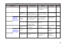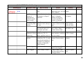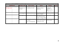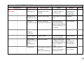
1
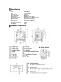
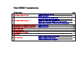
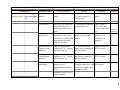
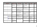
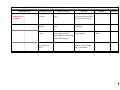
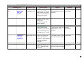
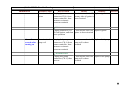
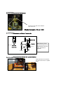
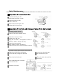
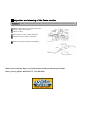
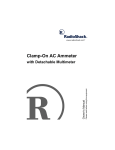
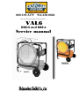
800-292-3279 916 638-0828
http://easycleansystems.com/heaters/heater-parts.html
VAL6
KBE5S and KBE5L
Service manual
KBE5S
1 Specifications
Type
Heat Output
Fuel
Tank Capacity
Fuel Consumption
Power Source
Power Consumption
Ignition System
VAL6 KBE5S
111,000BTU/h
Kerosene, Diesel
9 gallons
0.85gallon/h
120V, 60Hz single phase
80W (in burning), 100W (in igniting)
High Intensity Discharge
EXTERNAL DIMENSION (L/W/H) 27.4/27.9/36.2(in) [695/708/918(mm)]
Safety Device
Photocell Flame Monitor
Overload Check Device
3A Fuse
Dry Weight
83.8lbs
2 Names of Components
3 Wiring Diagram of Burner Control
PS : Power Source
SW1 : Operating Switch
TH : Thermostat (Short)
FE : Flame Monitor
FG : Frame Ground
HT : Pre Heater
FM : Fan Motor
CM : (Open)
IG : Igniter
SP : Solenoid Pump
SV : (Open)
RL : Running Lamp
AL : Misfire Lamp
KA : Control Relay
F : Line Fuse
Z : Surge Absorber
ES : Emergency (Short)
CN6 CN3
CN7
CN12
CN1 CN2 CN4 CN5
CN11 CN10 CN9 CN13 CN8
RUN
Conn ector No.
CN1
Power Source
CN2
CN3
Fan Motor
CN4
Igniter
CN5
CN6
Solenoid Pump
CN7
Tran
CN8
Operating Switch
CN9
Thermostat (Short)
CN10
CN11
Flame Monitor
Runnin g Lamp,
CN12
Misfire Lamp
CN13
-
MISFIRE
Sequence Time Chart
ON
ignition
OFF
Operation
Switch
Fan
Igniter
Solenoid
Pump
5 sec.
within
10 sec.
10 sec.
(post ignition)
180 sec.
VAL6 KBE5S Troubleshooting
Phenomenon
1 The heater does not start
2 The heater does not ignite
3
4
5
6
7
8
Misfire within 25 seconds after ignition
Combustion stop during the operation
Odor comes out
Smoke comes out
Combustion is not stable
Fuel leaks
9 Fuse blows out
page
The lamp does not light on
Misfire lamp is lit
Fuel pump does not operate at all
No fuel or a little fuel is pumped up
Igniter does not spark. [Igniter does not operate]
Sequence of operation is normal, but it doesn't ignite
Misfire lamp is lit
Misfire lamp is lit
1
3
5
6
7
8
9
When the plug is put into the socket
When the switch is turned on
About 5 seconds after turning on
10
VAL6 KBE5S Trouble Shooting
Phenomenon
Possible Cause
How to check
Result
Remedy
No power source Measure voltage of AC If circuit tester indicates Connect power
1.The heater The lamp
outlet.
0V, power source is
source
does not start. does not light supplied
disconnected
on.
Standard: AC120V
Fuse blowout
Take fuse out from fuse
box, and then check
each lead with circuit
tester
Disconnection of Take power source
power cord
connector (CN 1) out
from burner control, and
then check each lead
with circuit tester
If circuit tester reads ∞ Find a cause of
Ω, fuse blows out
blown fuse and
replace with a new Picture 8
one
Picture 9
If either of the lead is
Make sure the
broken, power cord is
power cord is
broken
connected, or
replace it
Loose connection Plug in power source
If it works normally,
Plug in connector
of power source connector (CN 1) again, power source connector (CN 1) firmly
connector
and then turn on
fails on contact
Loose connection Plug in transformer
If it works normally,
of transformer
connector (CN 7) again, transformer connector
connector
and then turn on
fails on contact
Failure of
transformer
Measure voltage at
output side of
transformer connector
(CN 7)
Reference
Plug in connector
(CN 7) firmly
If tester reads normal
Replace
voltage at input side, and transformer
reads 0V at output side,
transformer fails
Standard: about AC15V
(purple-purple)
1
VAL6 KBE5S Trouble Shooting
Phenomenon
Possible Cause
How to check
Result
Loose connection Plug in operation switch If it works normally,
of operation
connector (CN 8) again, operation switch
switch connector and then turn on
connector fails on
contact
Failure of
Take operation switch If it doesn't conduct
operation switch connector (CN 8) out, when turned on,
then check lead with
operation switch fails
circuit tester
Standard: Conducting (0
Ω) when turned on
Failure of burner Measure voltage at input If power source is
control
side of transformer
normal and tester reads
connector (CN 7)
0V at input side, burner
control fails
Standard: AC120V
(white-red)
Run lamp is Loose terminals Firmly connect terminals If it works normally,
on control device for control device
terminals for control
lit
device are loose
Unplug flame monitor It starts to operate
Misfire lamp Flame monitor
sensor
connector (CN 11), and
is lit.
malfunctions
then start operation
Failure of burner
control
Reference
Remedy
Plug in connector
(CN 8) firmly
Replace operation
switch
Replace burner
control
Firmly connect
terminals on
control device
Avoid direct
sunlight on
radiation disk
Picture 6
It doesn't start to operate Replace burner
control
2
VAL6 KBE5S Trouble Shooting
Phenomenon
Possible Cause
How to check
Result
Loose connection Plug in fuel pump
If it works normally,
2.The heater Fuel pump
of fuel pump
connector (CN 6) again, fuel pump connector
does not ignite. does not
and turn on
fails in contact
operate at all. connector
Loose connection
of joint connectors
for fuel pump
Failure of fuel
pump
No fuel or a
little fuel is
pumped up.
Failure of burner
control
Fuel line is
clogged
Plug in joint connectors
for fuel pump again, and
then turn on
Measure voltage at
output side of fuel pump
connector on burner
control
Standard: AC60~96V
(red-blue)
Disconnect each fuel
line, and then clean up
each of them
Reference
Remedy
Plug in connector
(CN 6) firmly
If it works normally,
Plug in Joint
connectors on fuel pump connectors firmly
fails in contact
If voltage is normal, fuel Replace fuel pump
pump fails
If tester reads 0V, burner Replace burner
control fails
control
If it ignites after
・Clean fuel lines
cleaning, fuel flow
・Clean and rinse
decreases because of
the tank with
clogged in fuel lines
kerosene, alcohol
or acetone
Filter is clogged Check condition of filter If filter is dirty, amount ・Replace filter
of fuel flow decreases ・Clean and rinse
because of clogged filter the tank with
kerosene, alcohol
or acetone
Nozzle is clogged Replace nozzle
If it ignites, nozzle is
・Replace nozzle
clogged
・Clean and rinse
the tank with
kerosene, alcohol
or acetone
3
VAL6 KBE5S Trouble Shooting
Phenomenon
Possible Cause
How to check
Result
Remedy
Loose joint of fuel Check looseness of each If heater ignites by
Tighten joints
lines
joint
tightening joints, air leak
is the problem
Reference
Fuel pump is
Remove burner cover
No fuel is pumped up, Replace fuel pump
clogged, or failure and fuel outlet line, and fuel pump is clogged or
then turn on the switch failure
Picture 4
Plug in connector
Igniter does Loose connection Plug in igniter connector If it works normally,
of igniter
(CN 4) again, and then loose connection of
(CN 4) surely
not spark.
turn on the switch
igniter connector
[Igniter does connector
not operate.]
Failure of igniter Measure voltage at
If voltage is normal,
Replace igniter
igniter connector (CN4) igniter fails
on burner control
Sequence of
operation is
normal, but it
doesn't ignite
Failure of burner
control
Electrode is out of
alignment
Standard:AC120V
(black-black)
Measure the alignment
of electrode
If tester reads 0V, burner Replace burner
control fails
control
Refer to Picture 5
Replace electrode
(adjust the
position)
Picture 5
Improper amount Check gate opening of
of combustion air fan motor
Find adequate amount of Adjust gate
air flow for better
opening.
combustion
Normal scale: 3
4
VAL6 KBE5S Trouble Shooting
Phenomenon
Possible Cause
Misfire lamp Loose flame
3.Misfire
monitor
is lit.
within 25
seconds after
Shortage of light
ignition.
sensed from flame
How to check
Open burner cover, and
check if the flame
monitor is in
Take flame monitor out,
and check condition of
its lens
Remove burner, and
then check clarity of
draft tube and vane
Check extent of
combustion air inlet
opening
Result
Remedy
If flame monitor comes Put in flame
off, it doesn't work
monitor firmly
If photorecepter is dirty,
sensor becomes less
sensitive.
If draft tube or fan is
dirty, it senses little light
If opening is too wide,
flame is short because
combustion air is too
much
Loose connection Plug flame monitor
If it works normally,
of flame monitor connector (CN 11)
flame monitor connector
again, and then turn on fails on contact
Failure of flame Unplug flame monitor If resistance doesn't
monitor
connector (CN 11), and change, flame monitor
then check transition of fails
resistance by changing
quantity of light into
flame monitor
Nozzle clogged
Replace nozzle
If it ignited, nozzle is
clogged
Filter clogged
Check clarity of filter
If filter is dirty, fuel
flow decreases because
of filter clogged
Reference
Clean the sensor
with soft cloth
Clean draft tube
and whirl vane
Picture 8
Decrease opening
to reduce
combustion air.
Normal scale: 3
Plug connector
(CN 11) firmly
Replace flame
monitor
Replace nozzle
Replace filter
5
VAL6 KBE5S Trouble Shooting
Phenomenon
Possible Cause
4.
Misfire lamp Air leak
Combustion
is lit.
stops during
Insufficient
amount of
pumping fuel
because vacuum
forms in tank
Shortage of light
detected by flame
monitor
Reference
How to check
Result
Remedy
Check looseness of each If heater ignites by
Fasten joints more
joint
tightening joints, air leak tightly
is the problem
Check if air intake of
If air intake of fuel
Clean air intake of
fuel gauge is clogged
gauge is clogged,
fuel gauge
with dust
amount of fuel flow
becomes insufficient
because of vacuum
Picture 10
Take flame monitor out, If lens of flame monitor Wipe lens of
and then check clarity of is dirty, it detects a little flame monitor
its lens
light
with soft cloth
Remove burner, and
If draft tube or whirl
Clean draft tube
then check clarity of
vane is dirty, flame
and whirl vane
draft tube and vane
monitor detects little
Picture 7
Flame monitor
Plug flame monitor
If it works normally,
Plug connector
connector is loose connector (CN 11)
flame monitor connector (CN 11) firmly
connection
again, and then turn on fails on contact
Failure of flame Unplug flame monitor If resistance doesn't
Replace flame
monitor
connector (CN 11), and change, flame monitor monitor
then check transition of fails
resistance by changing
quantity of light into
flame monitor
Nozzle clogged
Replace nozzle
If it works normally,
Replace nozzle
nozzle was clogged
Filter clogged
Check clarity of filter
If filter is dirty, fuel
Clean or replace
flow decreases because filter
of clogged filter
6
VAL6 KBE5S Trouble Shooting
Phenomenon
5.Smell of
fuel comes out.
Possible Cause
How to check
Quantity of
Check gate opening of
combustion air is combustion air inlet
too much
Nozzle clogged
Filter clogged
Wrong nozzle
Result
If opening is too
extensive, it burns
imperfectly
Remedy
Decrease gate
opening of
combustion air
inlet.
Normal scale: 3
Reference
Replace nozzle
If it works normally,
Replace nozzle
nozzle is clogged
Check condition of filter If filter is dirty, amount Replace filter
of fuel flow decreases
because of clogged filter
Check makers imprint of If makers imprint is
the nozzle
incorrect, the nozzle is
Mark: 0.85USgal/h 60° should not be used
H
Replace to a
correct nozzle
7
VAL6 KBE5S Trouble Shooting
Phenomenon
6.Smoke
comes out.
Possible Cause
How to check
Shortage of
Check extent of
combustion air
combustion air inlet
opening
Decrease of air
brought from fan
Check if fan is dusty
Result
Remedy
If combustion air inlet is Extend
too small, it burns in
combustion air
short of oxygen
inlet opening.
Normal scale: 3
If fan is dusty, it is short Clean fan
of air
Reference
Decrease
Measure voltage at
If voltage at power
Check voltage
revolutions of the power source connector source is lower than
fan
standard, combustion air
is decreased because of
low voltage
(Power source
voltage is
insufficient)
Standard: AC120V
Nozzle clogged
Replace nozzle
If it works normally,
nozzle was clogged
Using at high
Know the altitude
If using at higher than
altitude area (Low
the altitude of 3300ft,
oxygen
heater burns imperfectly
concentration)
because of lack of
oxygen
Wrong nozzle
Check makers imprint of If makers imprint is
the nozzle
incorrect, the nozzle is
Mark: 0.85USgal/h 60° should not be used
H
Replace nozzle
Extend
combustion air
inlet opening.
Normal scale: 3
Replace to a
correct nozzle
8
VAL6 KBE5S Trouble Shooting
Phenomenon
7.
Combustion is
not stable.
8.Fuel leaks.
Possible Cause
How to check
Result
Remedy
Loose joints in
Check looseness of each If any joints are loose, Tighten joints
fuel line
joint
air is absorbed into fuel
lines from loose joint
Loose joints in
fuel line
Check looseness of each If any joint is loose, fuel Tighten joints
joint
is leaking
Failure of drain
gasket
Remove drain bolt after Fuel leaks because of
removing fuel from
broken gasket
tank, and then check that
gasket isn't broken
Amount of fuel in Check the fuel level
the tank is too
much
Reference
Replace drain
gasket
Fuel overflows because Drain excess fuel
quantity of fuel in the
tank is too much
9
VAL6 KBE5S Trouble Shooting
Phenomenon
9.Fuse blows When the
out
plug is put
into the
outlet.
Possible Cause
How to check
Result
Remedy
Short circuit of
Unplug transformer
If either of the values is Replace a
transformer coil connector (CN 7) from 0Ω, transformer is short- transformer
burner controller, then circuited
measure coil resistance
values of two leads
Reference
Standard: about 350Ω
(white-red)
Standard: about 9Ω
(purple-purple)
When the
switch is
turned on.
・Without tester
Unplug transformer
If fuse doesn't blow out, Replace
connector (CN 7) from transformer is shorttransformer
burner controller, then circuited
put plug into AC outlet
Short circuit of fan Unplug fan connector
coil
(CN 3) from burner
controller, then measure
resistance between
terminals
・Without tester
Unplug fan connector
(CN 3), and then start
operation
If resistance value is 0Ω, Replace fan
fan coil is short-circuited
If fuse doesn't blow out, Replace fan
fan coil is short-circuited
10
VAL6 KBE5S Trouble Shooting
Phenomenon
Possible Cause
How to check
Short circuit of
Unplug igniter
igniter
connector(CN 4) from
burner controller, then
measure resistance
between terminals
Short circuit of
About 5
seconds after pump coil
turning on
Result
Remedy
If resistance value is 0Ω, Replace igniter
primary side of igniter is
short-circuited
Reference
・Without tester
Unplug connector (CN If fuse doesn't blow out, Replace igniter
4) from igniter, and then igniter is short-circuited
start operation
Unplug fuel pump
connector (CN 6) from
burner controller, then
measure resistance
between terminals
・Without tester
Unplug fuel pump
connector (CN 6), then
turn on
If resistance value is 0Ω, Replace fuel pump
pump coil is shortcircuited
If fuse doesn't blow out, Replace fuel pump
pump coil is shortcircuited
11
Chart1
Standard resistance of functional parts
Parts
Connector No
Lead
Condition
on
off
dark
light
input
output
input
output
Resistance
0Ω
∞Ω
over 2MΩ
under 10KΩ
about 350Ω
about 9Ω
about 4.5KΩ
Operation Switch
CN8
Yellow-Yellow
Photo Cell
CN11
Black-Black
Transformer
CN7
Red-White
Purple-Purple
Igniter
CN4
Black-Black
Solenoid Pump
CN6
Red-Blue
-
about 130Ω
Fan motor
CN3
Gray-Gray
-
about 10Ω
Remarks
gate:Normal scale 3 (60Hz)*
When heater is used above 3,000ft sea
level, adjust air inlet on fan motor for
better combustion
Chart2
Parts
Input & Output of Burner Control
Connector No
Lead
Condition
Voltage
Power code
CN1
Transformer
CN7
Igniter
CN4
Black-White
Red-White
Purple-Purple
Black-Black
-
input
output
input
AC 120V (±10%)
AC 120V (±10%)
about AC 15V
AC 120V (±10%)
Solenoid Pump
CN6
Red-Blue
-
AC 60~96V
Fan motor
CN3
Gray-Gray
60Hz
50Hz
AC 120V (±10%)
-
Picture 1 How to measure resistance
① Pull out a connector which you
will measure from burner
② Turn on the resistor and set resistor range
③ Insert the lead head of resistor to
connector [lead wire side] and measure
resistance
Picture 2 How to measure voltage
① Operate the heater
② Turn on the resistor and set AC
voltage range
③ Insert the lead head of resistor
to connector and measure
resistance
Picture 3 Removing a burner
screw
Unscrew two
screws and take a
burner cover off
Nut Unscrew three nuts
and take a burner off
Unscrew two silver nuts with holding
gold nuts and remove two fuel hoses
Picture 4 Inspection fuel pump
Remove a pipe and check whether
fuel comes out
Standard pressure 99 psi (±4)
Picture 5 Standard position of electrode
Electrode
Manufacturer does
not recommend to fix
electrode as they are
very sensitive to
position.
Nozzle
4±0.5mm
8±0.5mm
Electrode
10±0.5mm
Picture 6 Inspection terminals for control device
Check whether the terminals
for control device are coupled
firmly
Picture 7 Inspection draft tube
and fan
Picture 8 Inspection fuse①
Object Serial Number : 01S, 01R, 01Q-030000
whirl
draft
b
In case of draft tube and fan
are dusty, please clean them up
Open the fuse box and check whether
the fuse blows out
Picture 9 Inspection fuse②
Picture 10 Clean up fuel gauge
Object Serial Number :01Q-040000, 01P, 01N
Open a screw cap and
take out a fuse
Check
whether fuse
is blown out
If air intake of fuel gauge is
clogged, clean it up
air
i k
Daily Maintenance
Inspection of the tank inlet filter
1 Remove the fuel cap and
and check inlet filter is clean
2
If the inlet filter is dirty,
clean it with fuel
3 Place the inlet filter back and
tighten the fuel cap firmly
Inspection of the filter and drainage of water from the fuel tank
Checking the filter element
1 Check if the filter element is dirty
If the filter element if dirty
2 replace to a new one.
Plug the new filter in and tighten the metal ring
If dirt or water is found in the cup,
clean the cup throughly
3 Also clean the inside of fuel tank
Drain the dirty fuel from the bottom of the tank
Drainage of water/dirty fuel from the fuel tank
Drain the old fuel from the bottom
1 of fuel tank by loosing the drain bolt
Loose the drain bolt again
5 to drain the dirty fuel
2 Place the drain bolt back
6
Pour clean kerosene or alcohol
3 into the fuel tank
4 Shake the fuel tank
Place the drain bolt and fuel
cap firmly
Inspection and cleaning of the flame monitor
Observations - When removing the flame monitor, hold it by its main assembly; do not pull out the cord.
Remove the burner cover and pull out the
1 flame monitor, and check if
sensor is dirty
If the sensor is dirty, please wipe the
2 surface of its lens with a soft cloth
3
Place the sensor back into the position
Online parts ordering: http://easycleansystems.com/heaters/heater-parts.html
Order parts by phone: 800 292-3279 916 638-0828