1
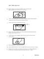
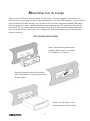
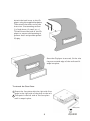
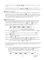
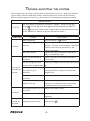
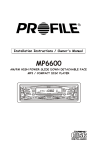
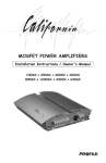
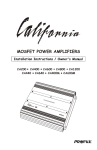
,
INSTALLATION INSTRUCTIONS / OWNER S MANUAL
CD8200
AM/FM HIGH POWER DETACHABLE FACE
CD PLAYER
INTRODUCTION
Congratulations on your purchase of a Profile state-of-the-art single disc CD
player. Your selection of a Profile car audio product indicates a true appreciation
of fine musical reproduction. Whether adding to an existing system or including
your Profile CD player in a new system, you are certain to notice immediate
performance benefits.
FEATURES
35W x 4 Power Output
Dual RCA Line Output(Front & Rear)
Auxiliary RCA Line Input
Clock
30 Station Memory
4 Band Preset Equalizer
Loud Function
Power Level Meter
ISO/DIN Mounting
Blinking Security L.E.D.
Full Electronic Function Controls
Disc Scan, Random & Repeat Play
KEEP YOUR SALES RECEIPT
Take this time to attach your sales receipt to the manual and put in a safe place.
In case of any reason this product may need warranty service, your receipt will
be necessary to establish purchase date.
,
IMPORTANT! Before making any connections, disconnect the car s battery
until the installation is completed to avoid possible damage to the electrical
system.
Serial #
Purchase Date
1
SAFETY PRECAUTIONS
Secure the CD player.
When installing your CD player in the vehicle, make sure it is mounted properly in the dash,
using an after market installation kit if needed. When using the supplied mounting sleeve,
it is a must that you also use the supplied back brace to support the back of the CD
player.
Use caution when mounting the CD player.
Remember there are many electrical wires, vacuum lines, brake lines and air bag deployment
wires. Make sure you know where they are when mounting the CD player to avoid puncturing
lines, and shorting wires.
Use high grade wire connectors.
To ensure maximum power transfer and secure safe connections, it is recommended to use
high grade barrel or crimp cap connectors.
Do not run any wires underneath the vehicle.
Exposed wires can be cut or damaged. It is best to run all wires through the vehicle under the
carpet and/or side panels. This enables to a cleaner installation and less risk of damage.
Run signal wires away from electrical wires
To avoid possibility of induced noise from the car's electrical system (i.e. popping noises or
engine noise), run signal wires away from the car's electrical wiring.
Make all ground wires as short as possible and terminated at the same point.
In order to reduce the chance of ground loops (i.e. engine noise), make the grounded wire as
short as possible to reduce the wire's resistance. Also, when using multiple components, make
sure all units are grounded at the same point.
Avoid sharp edges when running the wires.
To avoid the possibility of power, signal or speaker shorts, be careful not to allow the amplifier
wires to come in contact with sharp edges. Use a grommet to protect the wire when running
through the fire wall .
2
CD8200
CARE AND MAINTENANCE
Cleaning the CD player
When cleaning the vehicle, be sure not to get any water in or on the CD player. Clean only
the exterior surface of the unit with a dry, clean soft towel using no chemical solvents.
Operating in extreme temperatures
Sometimes the unit will not operate in extreme, hot or cold temperatures. If this is the case,
wait until the temperature in the vehicle is normal, then resume operation.
Protect your CDs.
When not using the disc player, it is recommended that you remove the CD.
Do not leave an ejected disc sitting on the edge of the disc player for long periods of time.
The disc will warp under direct sunlight. Always put each disc in its case to protect them
during times of non-use.
CD operation.
Never attempt to force anything other than a compact disc in the disc slot. This disc player
is a precision instrument that could be damaged by a foreign object.
Disc skip
When driving down a very rough road, the disc may skip. This will not scratch or damage the disc.
Removing and protecting detachable face plate.
The face plate of the radio may be removed as a theft deterrent. After removing the face
plate, use the case provided to keep the face plate from getting damaged.
FACE PLATE
PROTECTIVE CASE
OPEN BUTTON
FACE PLATE
( FIG.2)
( FIG.1)
Press the OPEN button to detach the face plate, then take the face plate away
from the head unit (Fig.1) and put it in the protective case (Fig.2) for safe keeping.
3
DISC CARE AND PLAY:
Before playing, clean the disc with a clean, lint-free cloth.
Wipe the disc in the direction of the arrow.
Do not use solvents such as benzine or thinners. Commercially available
cleaners or anti static spray will damage the unit.
Insert a disc with the labeled surface up.
Label
surface up
Do not try to insert another disc when one has already been inserted.
Doing so may damage the unit.
Handle the disc by its edge to keep the disc clean and do not touch
the surface.
Do not stick paper or tape on the disc.
Do not expose the disc to direct sunlight which can cause the disc to warp.
Always store the disc in its case for protection. Scratched up discs will
produce poor sound performance and cause CD player to skip.
4
CD8200
ELECTRICAL AND SIGNAL CONNECTIONS
Before making the following connections, take time to look over the vehicle's wiring and
determine the location and wires you will be connecting to. If you do not wish to cut or tap
into the vehicles existing factory wiring, there are wiring kits available at your car audio
retailer that will allow you to plug directly into the factory wiring harness. Make sure to
test all wires before connecting to the CD Player.
! Connect Black wire to chassis ground.
! Connect the Yellow memory backup wire to a Constant +12 Volt power source wire.
! Connect the Red ignition wire to a switched +12 Volt power source wire. (The power
wire that is energized when the key is in the accessory position).
! The blue wire is connected only if a power antenna or an amplifier is used in the
system. This wire supplies +12 Volt output when the CD Player is turned on,
which activates most power antenna relays or amplifier turn on circuits.
FOUR SPEAKER SYSTEM
ANTENNA CONNECTOR
BROWN
L
L CH WHITE
MEMORY +12V
-
+
BATTERY
+12V
Low level signal output for
connection to amplifier or
signal processors.
AUX RCA INPUT
R
R CH RED
YELLOW
BLACK(GND)
RED (B+)
SWITCHED +12V
(ON WITH IGNITION)
BLUE AUTO ANTENNA
+
FRONT LEFT
SPEAKER
FRONT RCA OUTPUT
FILTER
BOX
BLACK
REAR RCA OUTPUT
0.5A Fuse
GRAY
0.5 A
FUSE
WHITE
GRAY
VIOLET
GREEN
VIOLET/BLACK
GREEN/BLACK
5
R
R CH RED
L
L CH WHITE
R
R CH RED
L
L CH WHITE
+
FRONT RIGHT
SPEAKER
GRAY/BLACK
WHITE/BLACK
+
REAR LEFT
SPEAKER
1OA Fuse
+
REAR RIGHT
SPEAKER
TWO SPEAKER SYSTEM
ANTENNA CONNECTOR
AUX RCA INPUT
R
R CH RED
L
L CH WHITE
MEMORY +12V
YELLOW
BLACK(GND)
-
+
BATTERY
+12V
RED (B+)
SWITCHED +12V
(ON WITH IGNITION)
BLUE AUTO ANTENNA
FRONT LEFT
SPEAKER
CAUTION!
Low level signal output for
connection to amplifier or
signal processors.
BROWN
+
10A Fuse
FRONT RCA OUTPUT
FILTER
BOX
BLACK
REAR RCA OUTPUT
0.5A Fuse
GRAY
0.5 A
FUSE
WHITE
GRAY
WHITE/BLACK
GRAY/BLACK
NOT USED
NOT USED
NOT USED
NOT USED
R
R CH RED
L
L CH WHITE
R
R CH RED
L
L CH WHITE
+
FRONT RIGHT
SPEAKER
Tape unused wires so they do not short against other wires or
chassis ground.
6
CD8200
MOUNTING THE CD PLAYER
There are two different ways to mount the CD Player. In most Japanese vehicles you can
use the factory mounting brackets, taking advantage of the ISO/DIN opening. If your vehicle
does not have ISO/DIN opening, you can mount the CD Player using the supplied DIN sleeve
and rear support bracket. When considering your mounting location, make sure the unit will
be leveled. If you cannot mount the CD Player level, due to your vehicles design, make sure
there is no more than a 30 degree tilt. Keeping this in mind will assure proper CD play and
overall reliability.
DIN SLEEVE MOUNTING
Insert the mounting sleeve into a
standard DIN cutout in the dash
kit, dashboard or Console.
Bend the mounting tabs of the sleeve
with a screwdriver to secure the bracket
firmly in place.
Insert the CD Player in the
mounting sleeve until it locks.
7
Attach the back brace to the CD
player using the supplied hardware.
Then attach the other end of the
brace to a firm mounting surface
(i.e. Dash brace, fire wall, e.t.c.)
This will brace the back of the CD
player to ensure solid mounting to
prevent theft and provide optimal
CD play.
Once the CD player is secured, fit the trim
ring over outside edge of the radio until it
snaps into place.
To Attach the Face Plate:
1 Insert the face plate with the right side first.
Angle in the right side of the plate to the unit.
2 Then push in the left side of the face plate
until it snaps in place.
FACE PLATE
8
CD8200
ISO/DIN MOUNTING
If you own a Japanese vehicle, you can use the standard ISO/DIN mounting screw holes on
the side of the CD player to attach to the existing factory mounting bracket, without using
the provided DIN sleeve.
! Remove the factory ISO/DIN mounting bracket from the car along with the factory radio.
! Remove the factory radio from the bracket by unscrewing the two Phillips screws on each
side of the radio paying close attention to their screw positions and saving the screws to
mount the CD player.
! Remove the two spring clips from each side of the CD player by removing the screws.
These clips are not used in ISO/DIN mounting method and must be removed to expose the
ISO/DIN mounting holes.
! Also remove the detachable face and rectangular trim ring from the CD player and mount
the CD player to the factory ISO/DIN bracket using the screws that you removed from
the factory radio.
! Connect the wire harness and antenna plug to the back of the CD player. Then mount the
factory ISO-DIN bracket to the car.
Note: It is not necessary to attach the outer rectangular trim ring for ISO/DIN mounting
method.
REMOVING THE CD PLAYER
! To remove the CD player from an ISO/DIN mount, follow the above mounting procedure
in reverse order.
! To remove the CD player from a sleeve mount, use the pair of keys provided.
Remove the rectangular trim ring by
applying pressure with your finger
tips, then gently pull out away from
the dash.
PLACE FINGER TIPS HERE
Insert the provided removal key into the opening on each side of the CD player.
Push the keys inward until they snap in place. Firmly grab the keys and slowly
pull the CD player out away from the dash.
9
LOCATION AND FUNCTION OF CONTROLS
10
CD8200
1 POWER
To turn ON the unit, press any button except the
and
button.
To turn OFF the unit, press the
button for more than 2 seconds.
2 DETACH FACE PLATE
button to detach the face plate. This will allow you to remove
Press the
the face plate.
3 CD PLAY
To play a CD, gently insert the CD into the slot with the label side facing up. The
disc will automatically be loaded into the unit and start playing the first track of
the disc. The digital display will indicate the track number.
4 EJECT CD
To remove a CD once inserted, press the
the unit switches to radio mode.
5 VOLUME UP
Press the +
button. Once the CD is ejected,
,
button to increase the system s volume.
6 VOLUME DOWN
,
Press the - button to decrease the system s volume.
7 MODE
Press the MOD button to change among tuner (radio), CD (if disc is loaded),
and auxiliary input playing mode.
Radio
CD
AUX.
8 BAND
Under radio mode press the BND button to change between three FM bands and
two AM bands.
FM 1
FM 2
FM 3
AM 1
AM 2
9 10 RADIO TUNE & CD TRACK UP/DOWN, CD FAST FORWARD/REWIND
Under radio mode, press the I 9 or I 10 button momentarily and repeatedly
to change the frequency number up or down one step. Under SEEK 1 mode, press
and hold the I 9 orI 10 button for more than 2 seconds to seek to the next or
previous clear station. Under SEEK2 mode, press and hold the I 9 orI 10 button
to speedily change stations up or down. Changing stations will stop once the button
is released. (Please refer to
on page 13 on how to set the seek mode
between SEEK 1 and SEEK 2.)
11
In CD play mode, press the
track.
I
9 or I
10 button to move to the next or previous
In CD play mode, press and hold the I 9 or I
10 button to fast forward or
fast reverse through the song. The CD resumes playing when the button is released.
11 PRESET STATIONS
There are 6 numbered buttons to store into memory and recall stations for each
band. Select a band (if needed) as explained in 8 . Tune to a radio station that
you wish to store. Select, press, and hold a preset numbered button for 2 seconds
until you hear a beep indicating that the station has been stored in memory. To
recall a preset station, simply push the numbered preset button.
12 FUNCTION SELECT
SEL button allows you to display different functions for adjustments. Press the
SEL button momentarily and repeatedly to move the display from Volume, Bass,
Treble, Balance, and Fader functions. Use the + 5 and - 6 buttons to
adjust the selected mode. When the mode has not been adjusted for several
seconds, display and mode returns to normal radio or CD operation.
VOL
(Volume)
BAS
(Bass)
TRE
BAL
(Treble) (Balance)
FAD
(Fader)
VOLUME - Press the SEL button once. Adjust the volume level using the + 5
and - 6 buttons.
BASS - Press the SEL button twice. Adjust the bass level using the + 5 and
- 6 buttons.
TREBLE - Press the SEL button three times. Adjust the treble level using the
+ 5 and - 6 buttons.
BALANCE - Press the SEL button four times. Adjust the sound balance between
left and right speakers using the + 5 and - 6 buttons.
FADER - Press the SEL button five times. Adjust the sound balance between front
and rear speakers using the + 5 and - 6 buttons.
Press the SEL button for more than 2 seconds to display additional set of functions
for adjustments, such as DSP, Beep On/Off, SEEK 1 or 2, 12 Hour/24 Hour, and
Volume Last/Adjust.
DSP - The unit is equipped with 4 preset equalization modes. Press the SEL button
for more than 2 seconds to display DSP OFF. Then use + 5 button to
,
choose one of 4 following preset EQ s in the following order.
When using preset EQ modes you will not have access to Bass and Treble
settings.
DSP OFF
POP
ROCK
12
CLASSIC
FLAT
CD8200
BEEP - The beep sound when you press a button on the unit can be turned on or
off. Press the SEL button for more than 2 seconds to display the DSP
function. Press the SEL button again momentarily to display BEEP ON/OFF.
Then use + 5 button to turn on/off the beep sound.
SEEK- The unit is equipped with two types of seeks, SEEK 1 and SEEK 2, for radio
stations. Press the SEL button for more than 2 seconds to display the BEEP
function. Press the SEL button twice momentarily to display SEEK 1 or 2.
Then use + 5 button to switch between SEEK 1 and SEEK 2.
(This adjustment is only available during radio operation)
SEEK 1 mode: Pressing I 9 orI
10 button for more than 2 seconds will seek
up or down to the next strong station during radio operation.
SEEK 2 mode: Pressing I 9 orI 10 button continuously will speedily change
station up or down until the button is released.
12 H / 24 H- The unit is equipped with two types of clock formats, 12 Hour and 24
Hour. Press the SEL button for more than 2 seconds to display the DSP
function. Press the SEL button three times momentarily to display 12H
or 24 H. Then use + 5 button to choose between 12 H and 24 H.
SET VOL - A certain volume level can be set to come on when the unit is turned
on or can be set to come on at the same last level before the unit was
turned off. Press the SEL button for more than 2 seconds to display
the DSP function. Press the SEL button four times momentarily to
display VOL LAST/ADJ. Use + 5 button to choose between VOL LAST
and VOL ADJ. To set the volume to a certain level, press the
SEL button momentarily when VOL ADJ is displayed. Then use + 5
and - 6 buttons to adjust to certain volume level when A-VOL is
displayed.
13 CD TOP/PAUSE
In CD play mode, press the TOP
resume normal play.
13 button to pause CD play. Press again to
In CD play mode, press the TOP
13 button for more than 2 seconds to go back
to the top of the disc and play the first track.
14 CD SCAN
In CD play mode, press the INT 14 button to turn on intro playing first 10
seconds of each track. When wish to listen to the whole track during intro mode,
press the button again to turn off intro.
15 REPEAT PLAY
In CD play mode, press the RPT 15 button to continuously playing the current
track. Press it again to cancel the repeat feature.
13
16 RANDOM PLAY
In CD play mode, press the RDM 16 button to play all tracks of the disc in random
sequence. Press it again to cancel random play.
17 LOUDNESS
Press LOU button once to enhance the bass effect.
Press again to cancel the loudness effect.
18 AUTOMATIC STORING & PRESET SCANNING
In radio mode, press and hold the A.P. 18 button for more than 2 seconds to
activate the automatic storing function. Once activated, the radio starts searching for first 6 strong signaled stations and stores them into the preset memory.
After completion, the radio will tune back to the first preset memory station.
In radio mode, press the A.P. 18 button momentarily to activate the preset
scanning function. Once activated, the radio starts scanning all preset memory
stations for few seconds at a time while the preset memory number flashes on
the LCD. Pressing the button again will stop the scan.
19 MUTE
Press the MU button to silence the system. Press a second time to resume
listening.
20 MONO/STEREO
Monaural (Mono) or Stereo mode can be selected for FM tuner, s reception. For
best quality sound, stereo mode should be selected. However, Mono mode can be
selected to help the reception of distant radio stations. Press the ST button to
select between Mono and Stereo modes.
21 CLOCK
Press the CLK button to display the time on the LCD for 5 seconds. To adjust the
time, press and hold the CLK button until the hour flashes and use the + 5 and
- 6 buttons to adjust the hour. Press and hold the CLK button again until the
minute flashes and use the + 5 and - 6 buttons to adjust the minute.
22 RESET
The reset button should be pressed when installation is complete and also when
all buttons do not operate.
23 SECURITY LED
Designed as a theft deterrent, the red LED will flash when the unit is turned off
and face plate removed.
14
CD8200
TROUBLE SHOOTING THE SYSTEM
The following chart will help in solving most problems that may occur. Should any problem
persist after you have made these checks, please consult your nearest Profile retailer.
Before going through this check list, refer back to the wiring and operating procedures.
ERROR CODES
The unit cannot be operated because of trouble. Press the "RESET"
E 1~ E 10
button 22 . If the indicator still appears after pressing the "RESET"
Button 22 , your unit needs repair. Please refer to the warranty section
of this manual for details on getting the unit serviced.
SYMPTOM
CAUSE
New installation.
SOLUTION
Press the RESET 22 button.
The vehicle's ignition switch Turn the ignition switch to the accessory
No Power
is not on.
position. If there is still no power, check the
fuses at the vehicle's fuse block or the
The fuse is blown.
radio's fuse leads.
Replace the fuse with another fuse of the
same recommended value
There is a disc already in
Remove the disc in the player, then put in
the player.
the new one.
You are trying to put the
Insert the compact disc with the label facing
compact disc in upside down. up.
Disc cannot
be loaded or
ejected.
The compact disc is
Clean the compact disc with a compact disc
extremely dirty or
cleaning solution or replace the defective
defective.
compact disc.
The temperature in the car
Cool the inside of the vehicle, then try again.
is too hot.
Condensation build-up on the Leave the disc player off and turn the
inside of the unit.
vehicle's air conditioner on to remove the
condensation build-up inside the unit.
The volume control is all the Adjust the volume control.
way down.
No sound.
The speakers are bad.
Test the speakers to determine if they need
replacing.
The function The built-in microprocessor
Remove the disc, then re-insert it. Press the
buttons do
reset button 22 .
is operating incorrectly.
not work.
15
SYMPTOM
CAUSE
SOLUTION
The compact The installation angle is
Adjust the angle of the unit to less than 30
disc skips.
greater than 30 degrees
degrees
The disc player is installed
Check to see if the unit is fastened securely
incorrectly
with the back brace supporting the rear of
the unit.
The compact disc is
Clean the compact disc with a compact disc
extremely dirty or defective cleaning solution or replace the defective
disc.
compact disc.
Condensation build-up on the Leave the disc player off and turn the
inside of the unit.
vehicle's air conditioner on to remove the
condensation build-up inside the unit.
The radio
The antenna is not
does not
connected or the antenna is proper performance.
work. The
bad.
Radio station
automatic
selection
Check the antenna and connection to insure
The signals in your listening
Select stations manually and make sure the
area are weak.
tuner is in the distant stereo mode.
does not
work.
16
CD8200
SPECIFICATIONS
GENERAL
Power Supply Requirements...........................................DC 12 Volts, Negative Ground
||
||
||
Chassis Dimensions ...................................................................7 (W) x 6 1/2 (D) x 2 (H)
Tone Controls...........................................................................................................................
Bass @ 100Hz..........................................................................................+10dB / -10 dB
Treble @ 10Khz.......................................................................................+10dB / -10 dB
Equalizer..................................................................................................................4 Presets
Maximum Output Power.........................................................................................35W x 4
RMS Output Power..................................................................................................20W x 4
Maximum Current Consumption........................................................................10 Ampere
Fuses
Memory (Constant)........................................................................................10 Ampere
Accessory (Switched).................................................................................0.5 Ampere
RCA line out voltage......................................................................................................3.7 V
CD PLAYER
Signal to Noise Ratio...................................................................................................>85dB
Channel Separation......................................................................................................>80dB
Frequency Response........................................................................................5Hz ~ 20Khz
Usable Disc....................................................................................CD/CD-R/CD-RW Discs
RADIO
FM
Frequency Coverage..............................................................................87.5 to 107.9MHz
IF................................................................................................................................10.7MHz
Station Presets...................................................................................................................18
AM
Frequency Coverage.................................................................................530 to 1710KHz
IF.................................................................................................................................450KHz
Station Presets...................................................................................................................12
Due to continuing product improvement, specifications subject to change without notice.
17
LIMITED WARRANTY
Profile Consumer Electronics, Inc. warrants this product to be free from defects in
material and workmanship for a period of One (1) Year from the date of sale to the
original consumer purchaser. If this product is proven to be defective within this one
year period, Profile will repair it when said product is returned, with a copy of the
dated sales receipt, freight prepaid to Profile.
This warranty is valid only in the United States. This warranty does not cover any
expense incurred in the removal and/or re-installation of this product. This warranty
does not cover any Profile product damaged by accident, misuse, abuse, improper line
voltage, fire, water, lightning, or other acts of God. This warranty is void if any parts
and/or service is/are furnished by anyone other than Profile. This warranty is void if
the factory applied serial number is altered or removed from the product.
This warranty does not cover cartons, cases, batteries, broken or marred cabinets,
magnetic tapes, or any other accessories used in connection with this product or
consequential damages due to a defect in the product.
Any implied warranties, including fitness for use and merchantability, are limited in
duration to the period of the express warranty set forth above. No person is
authorized to assume for Profile any other liability in connection with the sale of the
product. Profile expressly disclaims liability for incidental and consequential
damages that might be caused by this product. The remedies provided under this
warranty are exclusive and lieu of all others.
This warranty gives you specific legal rights. You may have other rights which vary
from state to state or province to province. Some states or provinces do not allow
limitation on how long warranties last, so the above may not apply to you. Additionally,
some states/provinces do not allow the exclusion to limitation of consequential or
incidental damages, so the above limitation or exclusion may not apply to you.
* In the space below, record the serial number that is located on the back of the unit
along with the purchase date and location.
Model Number __________________
Serial Number
____________________
Purchase Date __________________
Where Purchased _________________
RETAIN YOUR SALES RECEIPT ALONG WITH THIS CARD. IT IS YOUR ONLY
VALID DOCUMENT TO RECEIVE WARRANTY SERVICE.
WARRANTY REPAIR POLICY
In the unlikely event of product failure, the following procedures
should be followed
1) The unit must be under the 1-year warranty period.
2) The unit must have no physical damage.
3) A copy of the original proof of purchase must be sent with the unit.
4) Include a brief description of the problem or failure with the unit.
5) Include the return street address and daytime telephone number.
6) Allow 2~3 weeks for repair (this period includes shipping time).
Send unit to:
Note:
PROFILE CONSUMER ELECTRONICS, INC.
15060 SHOEMAKER AVE
SANTA FE SPRINGS, CA 90670
TEL: (562) 404-9393
All units failing to meet the above requirements will be
subject to a charge and or may not be repaired.
PROFILE CONSUMER ELECTRONICS, INC.
15060 SHOEMAKER AVE
SANTA FE SPRINGS, CA 90670
TEL: (562)404-9393 FAX: (562)404-9433
WWW.PROFILEUSA.COM