1
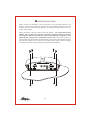
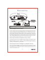
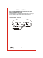
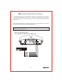
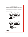
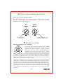
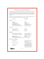
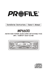
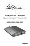
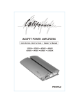
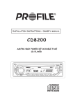
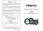
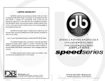
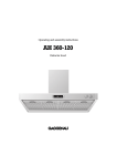
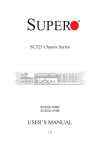
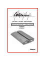
MOSFET POWER AMPLIFIERS
Installation Instructions / Owner's Manual
400MSX
600MSX
INTRODUCTION
Congratulations on your purchase of a California state-of-the-art power amplifier. Your
selection of a California car audio product indicates a true appreciation of fine musical
reproduction. Whether adding to an exi sting system or including your California amplifier in a
new system, you are certain to notice immediate performance benefits.
KEEP YOUR SALES RECEIPT
Take this time to attach your sales receipt to the manual and put in a safe place. In case of any
unforeseen reason this product may need warranty service, your receipt will be necessary to
establish purchase date.
RECOMMENDATION
A power amplifier's performance is only as good as its installation. Proper installation will
maximize the system's overall performance. It is recommended that you have our product
installed by an authorized Profile retailer. However, if you decide to install it yourself, please
carefully read through this manual and take your time to do a quality installation.
IMPORTANT! Before making any connections, disconnect the car's battery
until the installation is completed to avoid possible damage to the electrical
system.
WARNING!
Exposure to high power sound system can cause hearing loss or damage.
Listening to your system at loud levels while driving, will impair your ability to
hear traffic sounds and emergency vehicles. Use common sense when listening
to your system.
Serial #
Model #
1
SAFETY PRECAUTIONS
Fuse amplifier's power wire at the battery.
Be sure to fuse the power wire within 12" of the car's battery. This will protect the car's
battery in case of a short circuit between the power amplifier and battery. THIS IS A MUST,
the amplifier's built-in fuse will only protect the power amplifier not the car's battery!
Use high grade wire connectors.
To ensure maximum power transfer and secure safe connections, it is recommended to use
high grade connectors where needed.
Do not run any wires underneath vehicle.
Exposed wires have a chance of being cut or damaged. It is best to run all wires through the
vehicle under the carpet and/or side panels. This lends to a cleaner installation and less risk of
damage.
Use caution when mounting amplifier.
Remember there are many electrical wires, gas lines, vacuum lines, brake lines as well as a gas
tank in the automobile. Make sure you know where they are when mounting the amplifier to
avoid puncturing lines, shorting wires or drilling holes in the gas tank.
Run signal wires away from electrical wires.
To avoid possibility of induced noise from the car's electrical system (i.e. popping noises or
engine noise), run wires away from the car's electrical wiring.
Make all ground wires as short as possible and at the same point.
In order to reduce the chance of ground loops (i.e. engine noise), make the grounding wire as
short as possible to reduce the wire's resistance. Also, when using multiple components, make
sure all units are grounded at the same point.
Avoid sharp edges when running the wires.
To avoid the possibility of power, signal or speaker shorts, be careful not to allow the
amplifiers wires to come in contact with sharp edges. Use a grommet to protect the wire when
running through the fire wall .
2
FEATURES AND BENEFITS
DC Offset Protection
This circuit protects the output of the amplifier against DC voltage. If for some reason DC
voltage is detected at the output stage, the amplifier will shut down protecting the speakers
from direct current.
Short Circuit Protection
The circuit protects the amplifier from damage due to a short found in the speakers or wiring.
If one of the speakers or its wiring comes in contact with ground, the amplifier will shut down.
To resume normal operation, correct the problem and turn the head unit off, then back on.
The amplifier will reset and play again.
Thermal Protection
To protect the amplifier circuitry against damage caused by prolonged exposure to high
temperatures, a thermal protection circuit is activated if the amplifier reaches excessively
high operating temperature. Once the thermal circuit is activated, the amplifier will shut
down to cool off. The Amplifier will automatically turn back on once it cools down to a safe
operating temperature.
Protection Indicator
This red diagnostic L.E.D. indicates that the amplifier has gone into protection. Once on, the
amplifier will have no output. To resume normal operation, turn head unit off and back on again.
If the amplifier immediately goes back into protection, check for high temperature, short
circuits or low impedance.
Built-in Crossover
The amplifier is equipped with a built-in variable low pass crossovers. The crossover features
a variable frequency selection (40Hz ~ 130Hz) for precise high or low pass filtering.
Bass Boost
For added low frequency performance the amplifier is equipped with a variable 12 dB bass
boost.
3
Power Fusing
This protects the amplifier against short circuits and excessive current.
Remote Turn-on
Automatically turns amplifier on when connected to the head unit's remote output. The
amplifier will turn on and off with the head unit to save current consumption. This control also
operates the reset circuit for the amplifier's protection. It must be connected with the head
unit in order to reset protection circuits.
Gold Plated connections
For positive contact, maximum power and signal transfer with minimal resistance.
Adjustable Input Sensitivity
Allows you to fine-tune the level matching between your source and the power amplifier. The
controls have been set at the factory to accept average output of most radios, however, fine
tuning may be necessary to optimize signal to the amplifiers input stage.
High Level Input
Allowing for integration with "Factory Sound Systems".
Stable To 2 Ohm
Stability to 2 ohms allowing multiple speaker connections .
4
MOUNTING LOCATION
Before you start the installation, it will be necessary to find a mounting location for the
amplifier. Find a location in which the amplifier will receive adequate ventilation in order to
dissipate the heat it develops during operation. Two popular mounting locations are in the
trunk or under the seat.
Select the location in which you wish to mount the amplifier. Use caution when mounting
amplifier, there are many wires, gas lines, vacuum lines, brake lines as well as a gas tank in
the automobile. Make sure you know where they are when mounting the amplifier to avoid
puncturing lines, shorting wires or drilling holes in the gas tank. Once you are ready, use a
pencil to mark the mounting holes in the bottom panel. After you have marked the locations of
the holes move amplifier out of the way and drill small starter holes to make the tapping
screws easier to install. Use provided screws to tighten down the amplifier.
LP
X-over
85
Bass
Boost
Level
POWER
Input
Hi-Level Input
L+
Left
PROTECTION
40
130
0
12
Min
Max
Right
5
L-
R+
R-
POWER CONNECTIONS
Speaker Output
B+
GND
REM
Fuse
IN-LINE POWER FUSE
MOUNTED WITHIN 12"
FROM BATTERY RECOMMENDED
RADIO'S REMOTE
TURN-ON OUTPUT
(NOT PROVIDED)
-
+
CAR BATTERY
+12V
94.7
IMPORTANT! Before making any connections, disconnect the car's battery until the
installation is completed to avoid possible damage to the electrical system.
Connect the amplifier to the car's battery.
At times, the amplifier will need to draw large levels of current that cannot be provided by any
circuit in the car's fuse box. We recommended using a 4 to 8 gauge power wire for your
connections depending on the amplifier and length of the wire. Strip one end of the wire to
connect to the terminal on the amplifier marked B+. Loosen screw terminal and connect bare
wire and tighten. Use caution to make sure no stray wire stands come in contact with
surrounding terminals causing short circuits. Run the wire directly to the positive terminal of
the car's battery. Make sure to use an in-line fuse within 12" of the car's battery to protect
the electrical system and amplifier against short circuits and/or power surges.
Connect the ground terminal of the amplifier to the car's chassis.
For the ground connection, use a 4-8 gauge wire (black) to connect to the terminal marked
GND and then connect it to the car's chassis. Try to keep the length of the cable as short as
possible, preferably less than 6". Also make sure that the point on the car where the
connection is to be made is free of paint and dirt.
Connect the remote terminal of the amplifier to a switchable +12V source.
This connection allows the amplifier to be turned on and off with the power control of the
radio. If the radio has a REMOTE output terminal, connect it to the amplifier's terminal
marked REMOTE (using a 16 gauge wire or heavier). Now when the radio is turned on, the
amplifier will automatically turn on.
6
SIGNAL CONNECTIONS
Connect the output of the head unit (AM/FM cassette player, CD, or DAT)
to the RCA input terminals of the amplifier.
To make these connections, we recommend high quality RCA cables, which are available at your
local car audio retailer. Run signal wires away from electrical wires to avoid possibility of
induced noise from the car's electrical system (i.e. popping noises or engine noise).
TWO CHANNEL SIGNAL CONNECTIONS
LP
X-over
85
Bass
Boost
Level
Input
PROTECTION
POWER
Hi-Level Input
L+
Left
130
0
12
Min
Max
L
40
Right
R
94.7
7
L-
R+
R-
HIGH LEVEL CONNECTIONS (OPTIONAL)
If a low level RCA signal source is not available, you may still wire the amplifier with high-level
or speaker level outputs from your head unit. However, only speaker leads from a "floating
ground" system may be used (see diagram below). Use the provided plug to make the following
connections .
Note: The speaker leads from a "common ground" head unit systems should not be connected
to the hi-level input terminals of the following connections.
CAUTION! Before making any connections determine the type of radio to avoid possible
damage to amplifier and/or radio.
TWO CHANNEL CONNECTIONS:
FLOATING GROUND RADIO (MOST COMMON TYPE)
LP
X-over
Bass
Boost
85
Level
POWER
Input
Hi-Level Input
L+
Left
PROTECTION
40
130
0
12
Min
Max
Right
94.7
LEFT
LEFT
+
-
RIGHT
RIGHT
+
-
8
L-
R+
R-
SPEAKER CONNECTIONS
Make the speaker connections using speaker wire that is at least 10 gauge or
heavier.
As with any audio component, proper phasing of the amplifier and speakers is essential for
strong bass response. When connecting, make sure that positive (+) from the amplifier is
connected to the positive (+) of the speaker, and the same for negative (-).
SINGLE SPEAKER CONNECTION
Speaker Output
B+
REM
GND
B+
REM
GND
Fuse
-
+
4 Ohm Speakers
(2 Ohm Minimum)
TWO SPEAKER CONNECTION
Speaker Output
Fuse
-
+
-
+
4 Ohm Speakers
9
SETTING THE CROSSOVER AND BASS BOOST
Select your crossover type and frequency.
The amplifier is equipped with a built-in variable low -pass crossover network allowing you to
select the desired crossover point for your subwoofers.
Please refer to speaker
manufactures recommended crossover point.
Bass
Boost
LP
X-over
85
40
130
0
Select the crossover point
for your speakers.
12
You can add up to 12dB bass boost by
increasing the Bass Boost control.
FINE TUNE THE SYSTEM
Fine tune the amplifier's input sensitivity.
Level
Access to the gain sensitivity control for the California
amplifier is located on the side panel. This gain control has
been included to allow adjustment to properly match the
output of the radio. This is one of the most misunderstood
adjustments. By rotating the control in the clockwise
direction, the amplifier's input will become more sensitive and
Max
Min
the music will play louder. This is not a volume control and you will not get more power out of
the amplifier in the maximum position! It may seem to deliver more output, but actually the
system is only playing louder faster as you turn the volume control on the radio. Ideally, to
properly level match the system the goal is to achieve maximum output from the amplifier
without distortion at about 3/4 of the volume control.
To determine if the amplifier's gain is set properly, turn the system on and slowly increase the
volume control. You should be able to use about 3/4 volume before the system gets loud but
not distorting. It is very important when making these adjustments that you do not over drive
the speakers (at point of distortion) this will cause permanent damage to the speakers. If you
are unable to achieve 3/4 volume before distortion you will need to adj ust gain control (in this
case you would reduce the gain). The gai n controls should be adjusted very slowly. It may help
to have another person to assist you by adjusting the gain controls while you listen for
distortion.
10
TROUBLE SHOOTING THE SYSTEM
We have put together this trouble-shooting guide if you experience problems after installing
the amplifier. Please keep in mind that the majority of problems incurred are caused by
improper installation and not the equipment itself. In addition, there are many components in
the system that could cause various signal problems such as inducted electrical noise and
engine noise.
Before you can properly address the problem, you must first find the component that is
causing the problem. This will take patience and a process of elimination.
LOOK FOR....
SOLUTION
Blown fuse
Bad RCA Cable(s)
+12V at power terminal
+12V at remote terminal
Grounding point clean and tight
Head Unit's fader not in center position
Replace
Replace
Check connection
Check connection
Check for ground w/meter
Set to center position
No Output
Low Output
Check level adjustments
Bad RCA cable(s)
Improper level matching
Re-adjust
Replace
Re-adjust
Engine Noise
Grounding points are clean and tight
Ground all components at same point
Check for ground w/meter
Ground at same point
Change for better ground
Bad RCA cable(s)
Replace
High Quality shielded RCA cables
Rejects inducted noise
Low Vehicle charging system and/or battery Fix and/or replace
Protection L.E.D. Illuminated
Speaker short
Check speaker connection
for short circuit
Make sure speaker wires
do not touch chassis ground
Check speaker impedance
(Min 2 ohm Stereo, 4 Mono)
Check mounting location
for Adequate air Circulation
Speaker impedance too low
Speaker grounding out
Impedance too low
Overheating
11
SPECIFICATIONS
Max Power @ 4 Ohm
RMS Power @ 4 Ohm
Max Power @ 2 Ohm
RMS Power @ 2 Ohm
THD @ RMS Power
Frequency Response
Signal To Noise
RCA Input Sensitivity
RCA Input Impedance
High Level Input Impedance
Load Impedance
Crossover Type (12dB/Octave)
Crossover Frequency (Variable)
Bass Boost @ 45Hz (Variable)
Damping Factor
Power Terminal Size
Speaker Terminal Size
Fuse Value (ATC/ATO Type)
Size (H x D x W)
400MSX
600MSX
1 x 400W
1 x 200W
1 x 600W
1 x 300W
<0.07%
10Hz ~ 94Hz (at-1dB)
>105dB
200mV ~ 8V
16K Ohms
100 Ohms
2 ~ 8 Ohms
Low Pass
40Hz ~ 130Hz (at-3dB)
0dB ~ 12dB
250
4 Gauge
6 Gauge
2 x 20A
2 1/4" x 9 3/4"x 11 3/4"
1 x 600W
1 x 300W
1 x 850W
1 x 410W
<0.07%
10Hz ~ 94Hz (at-1dB)
>105dB
200mV ~ 8V
16K Ohms
100 Ohms
2 ~ 8 Ohms
Low Pass
40Hz ~ 130Hz (at-3dB)
0dB ~ 12dB
260
4 Gauge
6 Gauge
3 x 20A
2 1/4" x 9 3/4"x 16 1/8 "
Due to continuing product improvements, specification to change without notice.
12
LIMITED WARRANTY
Profile Consumer Electronics, Inc. warrants this product to be free from defects in
material and workmanship for a period of One (1) Year from the date of sale to the
original consumer purchaser. If this product is proven to be defective within this one
year period, Profile will repair it when said product is returned, with a copy of the
dated sales receipt, freight prepaid to Profile.
This warranty is valid only in the United States. This warranty does not cover any
expense incurred in the removal and/or re-installation of this product. This warranty
does not cover any Profile product damaged by accident, misuse, abuse, improper line
voltage, fire, water, lightning, or other acts of God. This warranty is void if any parts
and/or service is/are furnished by anyone other than Profile. This warranty is void if
the factory applied serial number is altered or removed from the product.
This warranty does not cover cartons, cases, batteries, broken or marred cabinets,
magnetic tapes, or any other accessories used in connection with this product or
consequential damages due to a defect in the product.
Any implied warranties, including fitness for use and merchantability, are limited in
duration to the period of the express warranty set forth above. No person is
authorized to assume for Profile any other liability in connection with the sale of the
product. Profile expressly disclaims liability for incidental and consequential
damages that might be caused by this product. The remedies provided under this
warranty are exclusive and lieu of all others.
This warranty gives you specific legal rights. You may have other rights which vary
from state to state or province to province. Some states or provinces do not allow
limitation on how long warranties last, so the above may not apply to you. Additionally,
some states/provinces do not allow the exclusion to limitation of consequential or
incidental damages, so the above limitation or exclusion may not apply to you.
* In the space below, record the model number that is located on the back of the unit
along with the purchase date and location.
Model Number __________________
Purchase Date __________________ Where Purchased _________________
RETAIN YOUR SALES RECEIPT ALONG WITH THIS CARD. IT IS YOUR ONLY
VALID DOCUMENT TO RECEIVE WARRANTY SERVICE.
WARRANTY REPAIR POLICY
In the unlikely event of product failure, the following procedures
should be followed
1) The unit must be under the 1-year warranty period.
2) The unit must have no physical damage.
3) A copy of the original proof of purchase must be sent with the unit.
4) Include a brief description of the problem or failure with the unit.
5) Include the return street address and daytime telephone number.
6) Allow 2~3 weeks for repair (this period includes shipping time).
Send unit to :
Note:
PROFILE CONSUMER ELECTRONICS, INC.
17625 FABRICA WAY
CERRITOS, CA 90703
TEL: (714) 690-4949
All units failing to meet the above requirements will be
subject to a charge and or may not be repaired.
By
PROFILE CONSUMER ELECTRONICS, INC.
17625 FABRICA WAY
CERRITOS, CA 90703
TEL: (714) 690-4949 FAX: (714) 690-4957
WORLD WIDE WEB: WWW.PROFILEUSA.COM