1
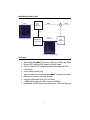
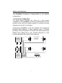
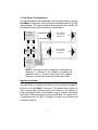
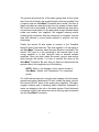
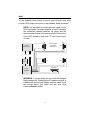
MaxxBass®
TABLE OF CONTENTS
Congratulations . . . . . . . . . . . . . . . . . . . . . . . . . . . . . . . . . . . . . . .2
Service . . . . . . . . . . . . . . . . . . . . . . . . . . . . . . . . . . . . . . . . . . . . . .2
Caution . . . . . . . . . . . . . . . . . . . . . . . . . . . . . . . . . . . . . . . . . . . . .2
Why Use MaxxBass® . . . . . . . . . . . . . . . . . . . . . . . . . . . . . . . . . .3
Why is MaxxBass® Better . . . . . . . . . . . . . . . . . . . . . . . . . . . . . .3
What is MaxxBass® . . . . . . . . . . . . . . . . . . . . . . . . . . . . . . . . . . . .4
How does MaxxBass® Work . . . . . . . . . . . . . . . . . . . . . . . . . . . . .5
MaxxBass® Signal Flow . . . . . . . . . . . . . . . . . . . . . . . . . . . . . . . .6
Features . . . . . . . . . . . . . . . . . . . . . . . . . . . . . . . . . . . . . . . . . . . . .6
Specifications . . . . . . . . . . . . . . . . . . . . . . . . . . . . . . . . . . . . . . . .7
Installation/Mounting . . . . . . . . . . . . . . . . . . . . . . . . . . . . . . . . . . .7
MaxxBass® Outline and Dimensions . . . . . . . . . . . . . . . . . . . . . . .8
Wiring Configurations . . . . . . . . . . . . . . . . . . . . . . . . . . . . . . . . . .9
Wiring Procedures . . . . . . . . . . . . . . . . . . . . . . . . . . . . . . . . . . . .10
Input . . . . . . . . . . . . . . . . . . . . . . . . . . . . . . . . . . . . . . . . . . . . . . .12
MaxxBass® Processor Settings . . . . . . . . . . . . . . . . . . . . . . . . . .13
Troubleshooting . . . . . . . . . . . . . . . . . . . . . . . . . . . . . . . . . . . . . .14
1
CONGRATULATIONS
Thank you for choosing PrecisionPowerTM audio equipment. At
PrecisionPowerTM we proudly design, engineer and manufacture
audio products for aftermarket car audio. Our award winning
engineering team utilizes innovative technology to consistently
deliver Absolutely State of the Art performance, sound quality,
reliability, and value. This PrecisionPowerTM product reflects our
commitment to offer you unparalleled versatility and quality for years
of dependable service and listening enjoyment.
SERVICE
Do not attempt to service PrecisionPowerTM products yourself.
Performing exploratory surgery on your audio equipment yourself
will void the warranty. Many parts of your PrecisionPowerTM gear are
custom built to our specifications. Our factory parts are not made
available to anyone else nor are they for sale. Our goal is to make
sure that your PrecisionPowerTM will always sound as good as the
day it was purchased. Contact your authorized PrecisionPowerTM
dealer about obtaining any warranty service through
PrecisionPowerTM. (See Warranty on back cover).
(Record listing for Model, Serial Number, and Purchase Date)
Model _____________________
Serial Number _______________
Purchase Date _______________
CAUTION
The extended use of a high-powered audio system may result in
hearing loss or damage. While PrecisionPowerTM systems are
capable of "Concert Level" volumes with incredible accuracy, they
are also designed for you to enjoy more reasonable levels all of the
sonic subtleties created by musicians. Please observe all local
sound ordinances.
2
WHY USE MAXXBASS
PrecisionPowerTM will introduce the first MaxxBass® processor to
the automotive market. The MaxxBass® processor is ideal for
improving the perceived bass response in door mounted speakers
without upgrading the speakers or amplifiers.
MaxxBass® provides subwoofer like performance with perceived
bass response to 30-40Hz on door mounted speakers. The
MaxxBass® Processor is recommended in two configurations.
(Please see Wiring Configurations for more details.)
1) Front Stereo Configuration
One MaxxBass® Processor is used between the front channel
source and front speaker amplifier to increase the bass response on
only the front speakers. This is recommended to improve bass
imaging in high performance systems with rear mounted
subwoofers.
2) Dual Stereo Configurations
For systems without rear subwoofers, the user may prefer to use two
MaxxBass® Processors, one for the front speakers and one for the
rear speakers. Although not nearly as good bass performance as
using a high performance subwoofer, this configuration will provide
close to subwoofer like performance without the space requirements
of a high performance subwoofer. This is a practical alternative for
bass performance where a subwoofer system can not be added.
WHY IS MAXXBASS BETTER
MaxxBass® is NOT a bass boost technology. Bass boost
technologies try to compensate for lack of bass frequency range by
equalizing or increasing the relative volume of the frequencies near
the speaker limit.
This increases amplifier and speaker excursion limits, which
can damage the system at high levels.
This destroys the intended frequency balance of music.
3
MaxxBass uses psychoacoustics to extend the perceived bass
frequency response.
It is proven to provide up to 1.5 octaves of increased bass
range.
It does not change the frequency balance of the music and
sounds more natural than large bass boosts.
It does not require more amplifier power and speaker
excursion.
It has been proven over many years of use in professional
audio recording.
WHAT IS MAXXBASS
MaxxBass® is a patented technology, which extends the bass
frequency range by allowing listeners to perceive bass frequencies
more than an octave below the physical limitations of speakers
systems. In cars MaxxBass® allows door mounted speakers that
typically drop off below 70-100Hz to play down another octave or
more.
This is accomplished using the science of psychoacoustics on how
we perceive sound. By building audio systems optimized for how we
hear sound, significant performance improvements can be obtained.
This is analogous to designing and building televisions that only
display red, green and blue dots. When we view these displays our
visual perception combines these dots to make a full color spectrum
without needing to reproduce all the necessary color frequencies.
Unlike other bass technologies MaxxBass® delivers more perceived
bass while simultaneously reducing the likelihood of damaging
speakers and amplifiers. MaxxBass® also delivers this extended
bass without any perceived distortion. MaxxBass® technology has
been used for years in mastering most of the world's most popular
music.
4
HOW DOES MAXXBASS WORK
MaxxBass® uses advanced digital signal processing based on the
proven psychoacoustic Phenomenon of the Missing Fundamental. A
basic description and a MaxxBass® Signal Flow diagram are
provided for interested users.
MaxxBass® first implements a crossover at the MaxxBass®
Frequency. The MaxxBass® Processor allows the choice of 60Hz,
generally suggested for 6-6.5" drivers, and 80Hz suggested for 45.25" woofer drivers.
The low pass filter (LPF) output of the crossover extracts the bass
signal which is below the bass frequency response of the system.
This is the signal to be reproduced psycho-acoustically and only this
signal receives the MaxxBass® processing. It is significant to note
that unlike bass boosts, MaxxBass® does not add or change the
processing of higher frequencies that can be reproduced by the
system. MaxxBass® does not change the artist's sound mix.
MaxxBass® uses a patented digital signal processing algorithm to
calculate precise harmonic content information which is added back
into the LPF signal. The combined LPF and harmonics output is high
pass filtered, thus removing the original bass signal. The processed
signal is then added back into the original HPF signal and the final
output provides a signal that sounds like the original, but no longer
has un-reproducible low frequencies.
5
MAXXBASS SIGNAL FLOW
Input
CrossOver
60/80 Hz
HPF
+
Output
LPF
Input Signal Example
LPF +
Harmonics
MAXXBASS®
Harmonics
HPF
60/80 Hz
Processed Signal Example
FEATURES
Selectable MaxxBass® Frequency Setting of 60Hz and 80Hz
Green LED clip/Red LED power indicator signal
Gold 2 Channel in/2 channel buffered full-range out RCA
connectors
4-pin locking power plug
Input connector for outboard MaxxBass® Intensity controller
Remote and on-box intensity controls
Intensity adjustment from 0 to full effect
-18dB/octave high pass filter output at 60/80Hz
Defeatable -24/dB octave low pass filter at 100Hz on the input
6
SPECIFICATIONS
Frequency
Signal-to-Noise Ratio
Separation
Crossover Slope
Input Impedance
Input Sensitivity
Output Level
Supply Voltage
20hz-20kHz
>85dB
65dB @ 1kHz
24dB/octave
20,000 Ohms
variable, 300mV to 3V peak to peak
variable, 300mV to 5V peak to peak
9 to 16 VDC
INSTALLATION/MOUNTING
NOTE: As an option, before beginning, disconnect the
negative (-) terminal of the battery to prevent an
electrical short to ground. Reconnect the negative
terminal only after all connections have been made.
To prevent damage to the MaxxBass® Processor while driving,
mount in a secure place. Choosing the appropriate location will
depend upon your vehicle and the complexity of your system design.
Typical mounting locations include the trunk and passenger
compartment (floor or under seat). Never mount the MaxxBass®
Processor in a location that would subject it to immersion or
exposure to water.
Once a location has been chosen, securely mount the MaxxBass®
Processor with the four mounting screws. Be Careful! Inspect the
area underneath to be sure you are not drilling into wires, brake or
fuel lines, etc. that could be damaged by the drill bits or screws.
7
MASSBASS OUTLINE AND DIMENSIONS
5.90 in
(15 cm )
5.51 in
(14 cm )
IN TEN SITY
O U TPU T
PO W ER
M IN
M AX
IN PU T
CLIP
M IN
M AX
M IN
M AX
4.53 in
2.48 in
(11.5 cm ) (6.3 cm )
80H z
ON
60H z
O FF
FR EQ U EN C Y
G N D R EM
C R O SS O VER
+12V R EM O U T
1.18 in
(3 cm )
IN PU T
O U TPU T
8
PO W ER
R EM O TE
WIRING CONFIGURATIONS
The MaxxBass® Processor is recommended in two different
configurations.
1. Front Stereo Configuration
The figure below illustrates the wiring for a front stereo
configuration. One MaxxBass® Processor is used between the front
channel source and front speaker amplifier to increase the bass
response only on the front speakers.
Implementing MaxxBass® on the front speakers will increase the
perceived bass response of these speakers down to 30-40Hz
providing a Virtual Subwoofer. The listener will achieve better bass
balance and imaging with a rear mounted subwoofer or trunk
mounted speakers with sufficient bass response.
In-dash
CD Receiver
Front
LF
Front speakers
with Virtual
TM
Subwoofer
RF
Rear
Maxx
Bass®
LR
RR
Subwoofer
Power
Amplifiers
9
2. Dual Stereo Configurations
For systems without rear subwoofers, the user may prefer to use two
MaxxBass® Processors, one for the front speakers and one for the
rear speakers. The units should be wired between the in-dash CD
Receiver and the power amplifiers as shown below.
In-dash
CD Receiver
Front
Maxx
Bass®
LF
Front speakers
with Virtual
TM
Subwoofer
RF
Rear
Maxx
Bass®
RF
Rear speakers
with Virtual
Subwoofer TM
RR
Power
Amplifiers
NOTE: As an option, before beginning, disconnect the
negative (-) terminal of the battery to prevent an
electrical short to ground. Reconnect the negative
terminal only after all connections have been made.
WIRING PROCEDURES
The next step is to connect the Power, Ground, and Remote IN/OUT
wires to your MaxxBass® Processor. The power wire should run
from the mounting location through the vehicle to the battery or
power distribution block. Avoid sharp corners, creases, and sharp
body parts. When passing through any metal wall (i.e. firewall, etc.),
a grommet must be used to prevent the wire from chafing and
shorting to ground.
10
The ground wire should be of the same gauge wire as the power
wire. As a rule of thumb, use as short length of wire as possible. Find
a location near the MaxxBass® Processor that is metal ( the floor is
ideal) and clean an area about the size of a quarter to bare metal.
Drill a pilot hole in the middle of this area. Terminate the wire with a
ring connector and attach it to the bare metal using a #8 sheet metal
screw and washer (not supplied). We suggest crimping and/or
soldering this connection. After the connection is complete, coat the
area with silicone or some similar material to prevent rust from
developing.
Finally, the remote IN wire needs to connect to the "Amplifier
Remote" lead of the head unit. This wire supplies a 12 volt signal to
the MaxxBass® Processor when the main System is activated. The
remote OUT wire is to be connected to the remote input of the
source amplifier or to and "optional" relay to activate multiple
amplifiers. Once you have routed the power, ground, and remote
wires through the vehicle, it is time to connect the wires to the
MaxxBass® Processor. Be sure that you have not reconnected the
ground cable to the negative post of the battery.
NOTE: Refer to the diagram of the system shown in
MaxxBass® Outline and Dimensions for connection
points.
Cut off the excess wire and, using the wire strippers, strip the power,
ground and remote cables about 1/8 inch. Locate the power, ground,
and remote IN/OUT wires of the power plug (supplied). We again,
suggest crimping and or soldering each connection separately to
insure no damage to the unit or the audio system. Check that each
connection is tight. If the wires are secure, the plug may be inserted
into the MaxxBass® Processor.
11
INPUT
To use Speaker Level Inputs (common ground head units only),
connect RCA plugs to the front or rear speaker leads as shown.
NOTE: It is important to connect an input signal to both
RCA input jacks if a stereo amplifier is used, otherwise
the connected channel receives full range and the
disconnected channel will receive only the harmonics.
Use a RCA female to dual male “Y” cord if mono input
is used.
In-dash
CD Receiver
Front
LF
Front speakers
with Virtual
TM
Subwoofer
RF
Rear
Maxx
Bass®
LR
RR
Subwoofer
Power
Amplifiers
WARNING: If you are using a source unit with bridged
high powered (or "floating ground") speaker outputs, a
suitable high to low level adapter must be used. If you
are unsure about your head unit see your local
PrecisionPowerTM dealer.
12
MAXXBASS PROCESSOR SETTINGS
To achieve proper performance it is important to set or tune the
settings on the MaxxBass® Processor to the final system. This
section recommends initial settings and the users can then further
adjust these for optimal listening.
1. CROSSOVER: The CROSSOVER control implements a 24dB/octave low pass filter on the input. Set the CROSSOVER
control to OFF if the amplifier and speakers after the MaxxBass®
Processor are full range speakers or if passive crossovers are used
in the speakers. Set the CROSSOVER control to ON, if the
MaxxBass® Processor is only used on a woofer channel and
separate amplifiers and speakers are provided for tweeters.
2. FREQUENCY: The FREQUENCY control should be set to 60Hz
for 6.5 inch door speakers and 80Hz for 5.25 to 4.0 inch door
speakers.
3. INPUT: The INPUT control is a signal attenuator for high voltage
inputs. The CLIP LED can be used to help set the maximum input
level setting prior to clipping. Start with INPUT control near MIN
position and increase INPUT level until the Clip LED lights
occasionally.
4. OUTPUT: The OUTPUT control provides a linear gain on the
output to help match signal levels to power amplifiers. Start with
OUTPUT control near MIN position and adjust accordingly to match
levels with other system components.
5. INTENSITY: The INTENSITY control provides an input to the
MaxxBass® algorithm on the level of the effect. Start with
INTENSITY near MIN position and increase until the desired level of
bass effect is obtained.
The INTENSITY control on the MaxxBass® Processor and Remote
Unit have identical functionality. At the MIN position on the
INTENSITY control, the MaxxBass® algorithm is in bypass, so that
no MaxxBass® processing occurs.
13
When the Remote INTENSITY control is plugged into the
MaxxBass® Processor, the Remote INTENSITY control become
active and the INTENSITY control on the MaxxBass® Processor is
disabled. This allows the user to install a remote control in a location
different than the MaxxBass® Processor and place in a more
convenient position for the listener such as underneath the
dashboard or in the glove compartment.
The INTENSITY control on the MaxxBass® Processor system is
only active when the Remote INTENSITY control is not plugged in.
This control is provided for users, who do not wish to use the
Remote INTENSITY control.
TROUBLESHOOTING
NO SOUND
Is the POWER LED lit?
YES
Check Input cables for signal by
Connecting them straight to the
Subwoofer amplifier.
NO
Check power and remote
turn-on wire for voltage.
Make sure the ground wire is
Secure.
ANY SOUND NOW?
YES
Problem is in the Crossover.
See your local Authorized
PrecisionPowerTM Dealer.
NO
Problem is elsewhere in the
system. Check head Unit and
amplifiers.
14
SOUND IN ONE CHANNEL ONLY
Reverse left and right RCA outputs for one band (i.e.-subwoofers)
SOUND IS NOW IN
OPPOSITE CHANNEL
Reverse RCA inputs
SAME CHANNEL
Problem is in the amplifier,
Speakers, or associated
wiring of the silent channel.
SOUND IS NOW IN
OPPOSITE CHANNEL
Reverse RCAs to head unit
(Check Balance Control)
SAME CHANNEL
Problem is in the Crossover.
See your local Authorized
PrecisionPowerTM dealer.
SOUND IS NOW IN
OPPOSITE CHANNEL
Problem is in the head unit.
SAME CHANNEL
Problem is in the RCA cables.
LOW OUTPUT FROM ONE BAND
Check crossover frequencies and check gain control on the effected
amplifier(s).
STILL LOW OUTPUT - See your local Authorized PrecisionPowerTM
dealer.
15
LIMITED TWO YEAR CONSUMER WARRANTY:
Directed Electronics, Inc. promises to the original purchaser, to replace this
product should it prove to be defective in workmanship or material under normal
use, for a period of two years from the date of purchase by the dealer as indicated
by the date code marking of the product PROVIDED the product was installed by
an authorized Directed dealer. During this two-year period, there will be no charge
for this replacement PROVIDED the unit is returned to Directed, shipping prepaid. If the unit is installed by anyone other than an authorized Directed dealer,
the warranty period will be 1 year from the date of purchase by the dealer as
indicated by the date code marking of the product. During this 1-year period there
will be no charge for this replacement PROVIDED the unit is returned to Directed,
shipping pre-paid. This warranty is non-transferable and does not apply to any unit
that has been modified or used in a manner contrary to its intended purpose, and
does not cover damage to the unit caused by installation or removal of the unit.
This warranty is void if the product has been damaged by accident or
unreasonable use, neglect, improper service or other causes not arising out of
defects in materials or construction. ALL WARRANTIES INCLUDING BUT NOT
LIMITED TO EXPRESS WARRANTY, IMPLIED WARRANTY, WARRANTY OF
MERCHANTABILITY, FITNESS FOR PARTICULAR PURPOSE, AND
WARRANTY OF NON-INFRINGEMENT OF INTELLECTUAL PROPERTY ARE
EXPRESSLY EXCLUDED TO THE MAXIMUM EXTENT ALLOWED BY LAW,
AND DIRECTED NEITHER ASSUMES NOR AUTHORIZES ANY PERSON TO
ASSUME FOR IT ANY LIABILITY IN CONNECTION WITH THE SALE OF THE
PRODUCT. DIRECTED HAS ABSOLUTELY NO LIABILITY FOR ANY AND ALL
ACTS OF THIRD PARTIES INCLUDING ITS AUTHORIZED DEALERS OR
INSTALLERS. Unit must be returned to Directed, postage pre-paid, with:
consumer’s name, telephone number, and address, authorized dealer’s name and
address, and product description. IN ORDER FOR THIS WARRANTY TO BE
VALID, YOUR UNIT MUST BE SHIPPED WITH PROOF OF INSTALLATION BY
AN AUTHORIZED DIRECTED DEALER. ALL UNITS RECEIVED BY DIRECTED
FOR WARRANTY REPAIR WITHOUT PROOF OF DIRECTED DEALER
INSTALLATION WILL BE COVERED BY THE LIMITED 1-YEAR PARTS AND
LABOR WARRANTY. Note: This warranty does not cover labor costs for the
removal and reinstallation of the unit. BY PURCHASING THIS PRODUCT, THE
CONSUMER AGREES AND CONSENTS THAT ALL DISPUTES BETWEEN THE
CONSUMER AND Directed SHALL BE RESOLVED IN ACCORDANCE WITH
CALIFORNIA LAWS IN SAN DIEGO COUNTY, CALIFORNIA.
© 2004 Directed Electronics, Inc. All rights reserved. G41830 01-04