1
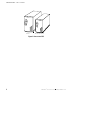
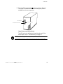
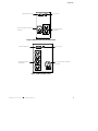
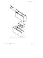
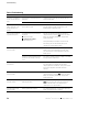
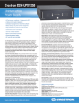
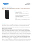
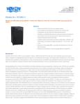
02/15/01
®
Powerware 3115
User’s Guide
300-650 VA
www.powerware.com
Powerware is a registered trademark of Powerware Corporation.
E
Copyright 1999 Powerware Corporation, Raleigh, NC. All rights reserved. No part of this document may be reproduced
in any way without the express written approval of Powerware Corporation.
Class B Statement for FCC and ICES
NOTE This equipment has been tested and found to comply with the limits for a Class B device pursuant to Part 15 of
FCC Rules. These limits are designed to provide reasonable protection against harmful interference when this equipment is
operated in a residential environment. This equipment generates, uses, and can radiate radio frequency energy and, if not
installed and used in accordance with the instruction manual, may cause harmful interference to radio communications.
However, there is no guarantee that interference will not occur in a particular installation. If this equipment does cause
harmful interference to radio or television reception, which can be determined by turning the equipment off and on, the
user is encouraged to try to correct the interference by one or more of the following measures:
S
S
S
S
S
Reorient or relocate the receiving antenna.
Increase the separation between the equipment and the receiver.
Connect equipment into an outlet on a circuit different from that to which the receiver is connected.
Consult the dealer or an experienced radio/TV technician for help.
Ensure that mounting screws, connector attachment screws, and all ground wires are secured and tight.
Changes or modifications not expressly approved by the party responsible for compliance could void the user’s authority to
operate the equipment.
For Users in Canada
This Class B Interference Causing Equipment meets all requirements of the Canadian Interference Causing Equipment
Regulations ICES-003.
Cet appareil numérique de la classe A respecte toutes les exigences du Reglement sur le matériel brouilleur du Canada.
Requesting a Declaration of Conformity
The EC Declaration of Conformity is available upon request for products with a CE mark. For copies of the EC
Declaration of Conformity, contact:
Powerware Corporation
Koskelontie 13
FIN-02920 Espoo
Finland
Phone: +358-9-452661
Fax: +358-9-452-66395
EMC Statement
Some configurations are classified under EN50091-2 as “Class-A UPS for Unrestricted Sales Distribution.” For these
configurations, the following applies:
WARNING This is a Class A-UPS Product. In a domestic environment, this product may cause radio interference, in which
case, the user may be required to take additional measures.
Special Symbols
The following are examples of symbols used on the UPS to alert you to important information:
CA U T I O N
Risk of Electric Shock
Do Not Open Cover
CAUTION To reduce the risk of electric shock,
Do not remove cover (or back)
No user-serviceable parts inside
Refer servicing to the factory
RISK OF ELECTRIC SHOCK - Indicates that a risk of electric shock is present and the
associated warning should be observed.
CAUTION: REFER TO OPERATOR’S MANUAL - Refer to your operator’s manual for
additional information, such as important operating and maintenance
instructions.
This symbol indicates that you should not discard the UPS or the UPS batteries
in the trash. The UPS may contain sealed, lead-acid batteries. Batteries must be
recycled.
TABLE OF CONTENTS
1 Powerware 3115 – One of the Best! . . . . . . . . . . . . . . . . . . . . . . . . . . . . . . . . . . 1
2 Installation . . . . . . . . . . . . . . . . . . . . . . . . . . . . . . . . . . . . . . . . . . . . . . . . . . . . . 3
Inspecting the Equipment . . . . . . . . . . . . . . . . . . . . . . . . . . . . . . . . . . . . . . . . . . . . . . . . . . . . . . .
Safety Precautions . . . . . . . . . . . . . . . . . . . . . . . . . . . . . . . . . . . . . . . . . . . . . . . . . . . . . . . . . . . .
Installing the UPS . . . . . . . . . . . . . . . . . . . . . . . . . . . . . . . . . . . . . . . . . . . . . . . . . . . . . . . . . . . . .
UPS Rear Panels . . . . . . . . . . . . . . . . . . . . . . . . . . . . . . . . . . . . . . . . . . . . . . . . . . . . . . . . . . . . . .
3
3
4
6
3 Operation and Configuration . . . . . . . . . . . . . . . . . . . . . . . . . . . . . . . . . . . . . . . 9
Turning the UPS On . . . . . . . . . . . . . . . . . . . . . . . . . . . . . . . . . . . . . . . . . . . . . . . . . . . . . . . . . . . . 9
Starting the UPS on Battery . . . . . . . . . . . . . . . . . . . . . . . . . . . . . . . . . . . . . . . . . . . . . . . . . . . 9
Turning the UPS Off . . . . . . . . . . . . . . . . . . . . . . . . . . . . . . . . . . . . . . . . . . . . . . . . . . . . . . . . . . . 9
Standby Mode . . . . . . . . . . . . . . . . . . . . . . . . . . . . . . . . . . . . . . . . . . . . . . . . . . . . . . . . . . . . . . . 10
How to Set DIP Switches . . . . . . . . . . . . . . . . . . . . . . . . . . . . . . . . . . . . . . . . . . . . . . . . . . . . . . . . 10
Communication Port Configuration . . . . . . . . . . . . . . . . . . . . . . . . . . . . . . . . . . . . . . . . . . . . . . . . . 11
4 UPS Maintenance . . . . . . . . . . . . . . . . . . . . . . . . . . . . . . . . . . . . . . . . . . . . . . . 13
UPS and Battery Care . . . . . . . . . . . . . . . . . . . . . . . . . . . . . . . . . . . . . . . . . . . . . . . . . . . . . . . . . .
Storing the UPS and Batteries . . . . . . . . . . . . . . . . . . . . . . . . . . . . . . . . . . . . . . . . . . . . . . . . . .
Replacing Batteries . . . . . . . . . . . . . . . . . . . . . . . . . . . . . . . . . . . . . . . . . . . . . . . . . . . . . . . . . . .
Testing New Batteries . . . . . . . . . . . . . . . . . . . . . . . . . . . . . . . . . . . . . . . . . . . . . . . . . . . . . . . . .
Recycling the Used Battery . . . . . . . . . . . . . . . . . . . . . . . . . . . . . . . . . . . . . . . . . . . . . . . . . . . . . .
13
13
14
17
17
5 Specifications . . . . . . . . . . . . . . . . . . . . . . . . . . . . . . . . . . . . . . . . . . . . . . . . . . 19
6 Troubleshooting . . . . . . . . . . . . . . . . . . . . . . . . . . . . . . . . . . . . . . . . . . . . . . . . . 23
Site Wiring Fault (120V Models only) . . . . . . . . . . . . . . . . . . . . . . . . . . . . . . . . . . . . . . . . . . . . . . .
Audible Alarms and UPS Conditions . . . . . . . . . . . . . . . . . . . . . . . . . . . . . . . . . . . . . . . . . . . . . . . .
Silencing an Audible Alarm . . . . . . . . . . . . . . . . . . . . . . . . . . . . . . . . . . . . . . . . . . . . . . . . . . . .
Service and Support . . . . . . . . . . . . . . . . . . . . . . . . . . . . . . . . . . . . . . . . . . . . . . . . . . . . . . . . . . .
Powerware® 3115 User’s Guide S www.powerware.com
23
23
23
25
i
Table of Contents
ii
Powerware® 3115 User’s Guide S www.powerware.com
CHAPTER
1
POWERWARE 3115 – ONE OF THE BEST!
The PowerwareR 3115 uninterruptible power system (UPS) protects
your sensitive electronic equipment from three basic power problems:
power failures, power sags, and power surges.
Power outages can occur when you least expect it and power quality can
be erratic. These power problems have the potential to corrupt critical
data, destroy unsaved work sessions, and damage hardware — causing
hours of lost productivity and expensive repairs.
With the Powerware 3115, you can safely eliminate the effects of power
disturbances and guard the integrity of your equipment. Ideal for PCs,
workstations, point-of-sale systems, network nodes, and similar
equipment, the Powerware 3115 provides cost-effective power
protection.
Because an integral part of power protection is power management
software, the Powerware 3115 comes fully equipped with a
communication port, serial cable, and a CD containing both LanSafe III
for networked systems and FailSafe III for standalone systems.
Providing outstanding performance and reliability, the Powerware 3115’s
unique benefits include the following:
S
Compact design conserves valuable space and makes the UPS easy to
install.
S
User-replaceable batteries extend the service life of your UPS.
S
The Site Wiring Fault indicator immediately informs you of wall
outlet wiring problems (available on 120V models only).
S
Audible alarms alert you of any fault conditions.
S
Start-on-battery allows you to power up the UPS even if utility power
is not available.
S
The Powerware 3115 is backed by worldwide agency approvals.
Powerware® 3115 User’s Guide S www.powerware.com
1
Powerware 3115 – ONE OF THE BEST!
650 VA
300 VA and 420 VA
Figure 1. Powerware 3115
2
Powerware® 3115 User’s Guide S www.powerware.com
CHAPTER
2
INSTALLATION
This section explains:
S
Equipment inspection
S
Safety precautions
S
UPS installation
S
UPS rear panels
Inspecting the Equipment
If any equipment has been damaged during shipment, keep the shipping
cartons and packing materials for the carrier or place of purchase and
file a claim for shipping damage. If you discover damage after
acceptance, file a claim for concealed damage.
To file a claim for shipping damage or concealed damage: 1) File with
the carrier within 15 days of receipt of the equipment; 2) Send a copy of
the damage claim within 15 days to your service representative.
Safety Precautions
Read the following precautions before you install the UPS.
IMPORTANT SAFETY INSTRUCTIONS
SAVE THESE INSTRUCTIONS. This manual contains important instructions that you
should follow during installation and maintenance of the UPS and batteries. Please
read all instructions before operating the equipment and save this manual for future
reference.
Powerware® 3115 User’s Guide S www.powerware.com
3
Installation
WARNING
S
This UPS contains its own energy source (batteries). The output receptacles may
carry live voltage even when the UPS is not connected to an AC supply.
S
Do not remove or unplug the input cord when the UPS is turned on. This removes
the safety ground from the UPS and the equipment connected to the UPS.
S
To reduce the risk of fire or electric shock, install this UPS in a temperature and
humidity controlled, indoor environment, free of conductive contaminants. Ambient
temperature must not exceed 40°C (104°F). Do not operate near water or
excessive humidity (95% max).
Installing the UPS
The following steps explain how to install the UPS. See “UPS Rear
Panels” on page 6 for the rear panel of each model.
1. If you are installing the power management software, connect
your computer to the UPS communication port using the
supplied communication cable.
NOTE If you need to change the factory-set defaults for output voltage or utility
power range, see “How to Set DIP Switches” on page 10 before installing the UPS.
2. On 230V models, plug the UPS power cord into the input
connector on the UPS rear panel.
3. Plug the UPS power cord into a wall outlet or other power
source.
4. Plug the equipment to be protected into the UPS output
receptacles.
DO NOT protect laser printers with the UPS because of the
exceptionally high power requirements of the heating elements.
4
Powerware® 3115 User’s Guide S www.powerware.com
Installation
5. Start the UPS by pressing the
button as shown in Figure 2.
The Power On indicator illuminates indicating that power is
available from the rear receptacles.
On/Off Button
Power On Indicator
Test/Alarm Reset Button
Figure 2. Powerware 3115 Front Panel
The UPS conducts a self-test and enters Normal mode. If the
alarm beeps, consult “Troubleshooting” on page 23.
NOTE The UPS charges to 90% in approximately 12 hours. However, it is
recommended that the UPS charge for 24 hours after installation or long storage.
Powerware® 3115 User’s Guide S www.powerware.com
5
Installation
UPS Rear Panels
This section shows the rear panels of all Powerware 3115 models.
Site Wiring Fault Indicator
Communication Port
DIP Switches
10A, Resettable
Circuit Breaker
Two 5-15 Output
Receptacles
Power Cord with
5-15 Plug
Figure 3. PW3 300 and PW3 420 Rear Panel
Site Wiring Fault Indicator
Communication Port
DIP Switches
10A, Resettable
Circuit Breaker
Four 5-15 Output Receptacles
Power Cord with
5-15 Plug
Figure 4. PW3 650 Rear Panel
6
Powerware® 3115 User’s Guide S www.powerware.com
Installation
Communication Port
10A, IEC-320 Input Connector
with Fuse
DIP Switches
Two IEC-320 Output
Receptacles
Figure 5. PW3 300i and PW3 420i Rear Panel
Communication Port
DIP Switches
Four IEC-320 Output
Receptacles
10A, IEC-320, Input Connector
with Fuse
Figure 6. PW3 650i Rear Panel
Powerware® 3115 User’s Guide S www.powerware.com
7
Installation
8
Powerware® 3115 User’s Guide S www.powerware.com
CHAPTER
3
OPERATION AND CONFIGURATION
This section covers:
S
Turning the UPS on and off
S
Starting the UPS on battery
S
Standby mode
S
How to set DIP switches
S
Configuring the communication port
Turning the UPS On
To turn on the UPS, press the
button on the front panel (shown in
Figure 2 on page 5). After the UPS is turned on, it conducts a self-test
and enters Normal mode. The Power On indicator illuminates indicating
that power is available from the rear receptacles.
Starting the UPS on Battery
To turn on the UPS without using utility power, press and hold the
button for three seconds. When the UPS starts on battery, it does not
conduct a self-test to conserve battery power.
NOTE The UPS does not automatically detect the input frequency when starting on
battery. The default frequency for 120V models is 60 Hz; the default frequency for 230V
models is 50 Hz.
Turning the UPS Off
To turn off the UPS, press the
button on the front panel and then
unplug the UPS from the power source. If you do not unplug the UPS, it
remains in Standby mode.
Powerware® 3115 User’s Guide S www.powerware.com
9
Operation and Configuration
Standby Mode
When the UPS is turned off and plugged into a wall outlet or other
power source, the UPS is in Standby mode. The battery recharges when
necessary and the Power On indicator is off, indicating that power is not
available from the rear receptacles.
How to Set DIP Switches
The DIP switches on the rear panel of each unit (see Figure 7) are used
to configure the output voltage and utility power range.
1. The UPS must be completely shutdown.
Turn the UPS off by pressing the
and then unplug the UPS.
button on the front panel
2. Set the DIP switches according to the DIP switch configurations
in Table 1.
3. Plug the UPS into a wall outlet or other power source and press
button to turn the UPS on.
the
UPS Rear Panel
DIP Switches
DIP Switch Detail
4 3 2 1
OFF
ON
Figure 7. DIP Switch Location
10
Powerware® 3115 User’s Guide S www.powerware.com
Operation and Configuration
Table 1. DIP Switch Settings
120V Models
Output
p Voltage
g
Utilityy Power
Range
DIP Switch 1
DIP Switch 2
DIP Switch 3
DIP Switch 4
110V
ON
OFF
120V*
OFF
OFF
127V
OFF
ON
OFF
OFF
98V - 142V
ON
ON
93V - 142V
OFF
ON
88V - 142V
ON
OFF
DIP Switch 3
DIP Switch 4
196V - 260V*
OFF
OFF
186V - 260V
ON
ON
176V - 260V
OFF
ON
166V - 260V
ON
OFF
103V - 142V*
230V Models
Output
p Voltage
g
Utilityy Power
Range
DIP Switch 1
DIP Switch 2
220V
ON
OFF
230V*
OFF
OFF
240V
OFF
ON
*Default position
Communication Port Configuration
To establish communication between the UPS and a computer, connect
your computer to the UPS communication port using the supplied
communication cable. Use only the factory-supplied cable and software.
See Table 2 for detailed information.
CAUTION
To prevent damage to your equipment, connect only a factory-supplied cable or a cable
built to factory specifications (see Table 2) to the communication port. A standard
serial cable may damage your computer.
Powerware® 3115 User’s Guide S www.powerware.com
11
Operation and Configuration
When the communication cable is installed, power management
software can exchange data with the UPS. The software polls the UPS for
detailed information on the status of the power environment. If a power
emergency occurs, the software initiates the saving of all data and an
orderly shutdown of the equipment.
6 7 8 9
1
2 3 4 5
Figure 8. Communication Port
Table 2. Communication Port Configuration
Pin Number
Signal Type
Function
1
Input: RS-232 high level signal for >0.4
seconds
Conditional Power Off: In absence of AC power, output is
turned off until normal AC power returns
2
Output: Open closing to logic ground pin 4
Impending Low Battery: Indicates the battery has less than 2
to 5 minutes of backup time left
3
Output: Open closing to logic ground pin 4
AC Input Failure: Indicates absence of normal AC input
4
Signal Return
Logic Ground
5
Output: RS-232 level low
Impending Low Battery: Indicates the battery has less than 2
to 5 minutes of backup time left
6
Output: RS-232 level high
AC Input Failure: Indicates absence of normal AC input
7
Not Used
Not Used
8
Not Used
Not Used
9
Chassis Ground (connected to pin 4)
Chassis Ground
12
Powerware® 3115 User’s Guide S www.powerware.com
CHAPTER
4
UPS MAINTENANCE
This section explains how to:
S
Care for the UPS and batteries
S
Replace the batteries
S
Test new batteries
S
Recycle used batteries
UPS and Battery Care
For the best preventive maintenance, keep the area around the UPS
clean and dust-free. If the atmosphere is very dusty, clean the outside of
the system with a vacuum cleaner.
For full battery life, keep the UPS at an ambient temperature of
25°C (77°F).
Storing the UPS and Batteries
If you store the UPS for a long period, recharge the battery every six
months by plugging the UPS into a power outlet. The UPS charges to
90% in approximately 12 hours. However, it is recommended that the
UPS charge for 24 hours after long storage.
Powerware® 3115 User’s Guide S www.powerware.com
13
UPS Maintenance
Replacing Batteries
The following steps explain how to replace the batteries. Consider all
warnings, cautions, and notes before replacing batteries.
WARNING
S
Batteries can present a risk of electrical shock or burn from high short circuit
current. The following precautions should be observed: 1) Remove watches, rings,
or other metal objects; 2) Use tools with insulated handles; 3) Do not lay tools or
metal parts on top of batteries.
S
The battery is not isolated from AC input. Hazardous voltage may exist between
battery terminals.
S
Replace batteries with the same number and type of batteries as originally
installed in the UPS.
S
The UPS must be unplugged from the AC power source before replacing batteries.
1. Turn off and unplug the equipment from the UPS.
2. Turn off the UPS and unplug the power cord from the power
source. Wait 30 seconds.
3. Turn the UPS over and remove the screw(s) holding the battery
door in place on the bottom of the UPS. Slide the door off (see
Figure 9 and Figure 10).
4. Gently pull out the battery by grasping the removal tabs.
5. Disconnect the two wires connecting the battery to the UPS.
6. Connect the battery wires to the new battery; red to
positive (+), black to negative (–). Carefully place the new
battery into the case.
7. Slide the battery door back into place and secure with the
screw(s) removed in Step 3.
8. Reconnect the power cord to the power source and turn the
UPS on.
9. Reconnect the equipment to the UPS. Turn on the equipment
one piece at a time.
14
Powerware® 3115 User’s Guide S www.powerware.com
UPS Maintenance
Black (–)
Red (+)
Figure 9. Replacing Batteries (300 VA and 420 VA models)
Powerware® 3115 User’s Guide S www.powerware.com
15
UPS Maintenance
Black (–)
Red (+)
Figure 10. Replacing Batteries (650 VA models)
16
Powerware® 3115 User’s Guide S www.powerware.com
UPS Maintenance
Testing New Batteries
NOTE It is recommended that the UPS charge for 24 hours before testing the new
batteries.
Press and hold the
button for three seconds to initiate the battery
test. The UPS automatically distributes some of the load to the batteries
for 15 seconds and tests the battery’s performance. If there is a problem
with the battery, the UPS returns to Normal mode and the alarm beeps.
For more information, see “Troubleshooting” on page 23.
Recycling the Used Battery
Contact your local recycling or hazardous waste center for information
on proper disposal of the used battery.
WARNING
S
Do not dispose of battery or batteries in a fire. Batteries may explode. Proper
disposal of batteries is required. Refer to your local codes for disposal
requirements.
S
Do not open or mutilate the battery or batteries. Released electrolyte is harmful to
the skin and eyes. It may be toxic.
CAUTION
Do not discard the UPS or the UPS batteries in the trash. This product contains sealed,
lead-acid batteries and must be disposed of properly. For more information, contact
your local recycling or hazardous waste center.
Powerware® 3115 User’s Guide S www.powerware.com
17
UPS Maintenance
18
Powerware® 3115 User’s Guide S www.powerware.com
CHAPTER
5
SPECIFICATIONS
This section provides the following specifications for the
Powerware 3115 models:
S
Electrical input and output
S
Battery
S
Weights and dimensions
S
Environmental and safety
Table 3. Model List
120V Models
230V Models
PW3 300
PW3 420
PW3 650
PW3 300i
PW3 420i
PW3 650i
120V Models
230V Models
120V default; 110, 120, 127V selectable
230V default; 220, 230, 240V selectable
UPS Models
Table 4. Electrical Input
Nominal Voltage
Power Factor
Voltage Range
0.6
User-selectable:
88V - 142V
93V - 142V
98V - 142V
103V - 142V (default)
User-selectable:
166V - 260V
176V - 260V
186V - 260V
196V - 260V (default)
Nominal Frequency
50/60 Hz
Online Efficiency
96%
Noise Filtering
Full-time EMI/RFI filtering
Overcurrent
Protection
10A, resettable circuit breaker
PW3 300i: 3.15A fuse (12.6A fault current)
PW3 420i: 3.15A fuse (12.6A fault current)
PW3 650i: 6.3A fuse (25.2A fault current)
Connections
6-foot power cord with a 5-15 plug (90° angle)
10A, IEC-320, input connector with fuse
Powerware® 3115 User’s Guide S www.powerware.com
19
Specifications
Table 5. Electrical Output
120V Models
230V Models
Power Levels
(rated at nominal inputs)
PW3 300: 300 VA, 180W
PW3 420: 420 VA, 252W
PW3 650: 650 VA, 400W
PW3 300i: 300 VA, 180W
PW3 420i: 420 VA, 252W
PW3 650i: 650 VA, 400W
Regulation Online
Less than 1% of nominal input voltage loss from input to output at full load
Overload Protection
Regulation On-Battery
(Nominal Voltage ±5%)
On-Battery Output
Frequency
On-Battery Voltage
Regulation
On-Battery Output Wave
Form
Overcurrent Protection
Connections
Online: 110 ±10% overload for 3 minutes; 120 ±10% overload for 10 cycles
On-Battery: 110 ±10% overload for 10 seconds; 120 ±10% overload for 1 second
120V default; 110, 120, 127V selectable
230V default; 220, 230, 240V selectable
50/60 Hz ±1 Hz of nominal frequency
±5%, -10% at low battery
Step wave (synthesized sine wave)
Online: resettable circuit breaker
On-Battery: active current limit and short
circuit protection
Online: replaceable fuse
On-Battery: active current limit and short
circuit protection
PW3 300: Two 5-15 receptacles
PW3 420: Two 5-15 receptacles
PW3 650: Four 5-15 receptacles
PW3 300i: Two IEC-320 receptacles
PW3 420i: Two IEC-320 receptacles
PW3 650i: Four IEC-320 receptacles
120V Models
230V Models
Table 6. Battery
Configuration
Voltage
Type
Charging
Monitoring
Backup Time
(typical full load)
Typical Life
20
Internal batteries
PW3 300: 1 each 12 Vdc battery
PW3 420: 1 each 12 Vdc battery
PW3 650: 2 each 6 Vdc batteries
PW3 300i: 1 each 12 Vdc battery
PW3 420i: 1 each 12 Vdc battery
PW3 650i: 2 each 6 Vdc batteries
Sealed, maintenance-free, valve-regulated, lead-acid
12 hours to 90% usable capacity at nominal line and no supplementary power supply load
Advanced monitoring for earlier failure detection and warning
PW3 300: 9 minutes
PW3 420: 5 minutes
PW3 650: 5 minutes
PW3 300i: 9 minutes
PW3 420i: 5 minutes
PW3 650i: 5 minutes
Minimum 3 years float service life at ambient temperature
Powerware® 3115 User’s Guide S www.powerware.com
Specifications
Table 7. Weights and Dimensions
120V Models
UPS Dimensions
(HxWxD)
UPS Weights
230V Models
PW3 300: 155 x 86 x 371 mm
(6.1 x 3.4 x 14.6 in)
PW3 420: 155 x 86 x 371 mm
(6.1 x 3.4 x 14.6 in)
PW3 650: 163 x 117 x 356 mm
(6.4 x 4.6 x 14.0 in)
PW3 300i: 155 x 86 x 371 mm
(6.1 x 3.4 x 14.6 in)
PW3 420i: 155 x 86 x 371 mm
(6.1 x 3.4 x 14.6 in)
PW3 650i: 163 x 117 x 356 mm
(6.4 x 4.6 x 14.0 in)
PW3 300: 5.2 kg (11.5 lb)
PW3 420: 5.2 kg (11.5 lb)
PW3 650: 7.5 kg (16.5 lb)
PW3 300i: 5.2 kg (11.5 lb)
PW3 420i: 5.2 kg (11.5 lb)
PW3 650i: 7.5 kg (16.5 lb)
Table 8. Environmental and Safety
120V Models
Operating Temperature
230V Models
0°C to 40°C (32°F to 104°F) 0 - 1500 meters above sea level
0°C to 35°C (32°F to 95°F) 1501 - 3000 meters above sea level
Storage Temperature
-15°C to 55°C (-5°F to 131°F)
Relative Humidity
0-95% noncondensing
Operating Altitude
Up to 3,000 meters above sea level
Audible Noise
Less than 45 dBA typical
Surge Energy Rating
More than 240 joules, 6500A
Surge Suppression
Meets IEEE 587/ANSI C62.41 Category A
IEC 801-5, Level 3
Safety Conformance
UL 1778; CAN/CSA C22.2, No. 107.1
EN 50091-1
UL, cUL
CE, NEMKO
FCC Part 15 Class B
EN 50091-2
Safety Markings
EMC
Powerware® 3115 User’s Guide S www.powerware.com
21
Specifications
22
Powerware® 3115 User’s Guide S www.powerware.com
CHAPTER
6
TROUBLESHOOTING
This section explains:
S
Site wiring fault on 120V models
S
UPS alarms and conditions
S
How to silence an alarm
S
Service and support
Site Wiring Fault (120V Models only)
The Site Wiring Fault indicator on the rear panel of the UPS illuminates
if the ground wire connection does not exist or the line and neutral
wires are reversed in the line receptacle. This indicator stays on until the
condition is resolved. Have a qualified electrician correct the wiring
fault. The UPS operates when the indicator is illuminated, but does not
provide rated noise and surge suppression.
Audible Alarms and UPS Conditions
The UPS has an audible alarm feature to alert you of potential power
problems. When the alarm is activated, the UPS beeps in different
intervals according to a particular condition. Use Table 9 to determine
and resolve the UPS alarms and conditions.
Silencing an Audible Alarm
To silence the alarm for an existing fault, press the
button. If UPS
status changes, the alarm beeps, overriding the previous alarm silencing.
The alarm does not silence if there is a UPS fault, low battery condition,
or if the battery needs to be replaced.
Powerware® 3115 User’s Guide S www.powerware.com
23
Troubleshooting
Table 9. Troubleshooting
Alarm or Condition
Possible Cause
Action
The Power On indicator is
not on; the UPS does not
start.
The line cord is not connected or not
plugged in.
Connect the line cord to the UPS and plug the UPS
into a working outlet.
The wall outlet is dead.
Have a qualified electrician test and repair the outlet.
The UPS operates in
Battery mode only, even
though normal AC is
present.
A circuit breaker or an input fuse on
the rear panel is open.
Save your work and turn off your equipment. Turn off
the UPS. Reduce the load, then push the circuit
breaker button or replace the fuse.
UPS does not provide the
expected backup time.
The battery may be fully discharged
because of:
S long-term storage
S frequent
requent power outages
S end of battery life
Plug the UPS into a power outlet for 24 hours to
charge the battery. Push the
button, if the alarm
beeps, see “Replacing the Battery” on page 14 to
replace the battery.
The UPS beeps 1 time
every 4 seconds.
During extended power outages, turn off the UPS
after saving your work and shutting down your
computer to conserve battery charge.
Utility power failed.
The UPS is powering your equipment with its internal
battery. If this is an extended power outage, save
your work and turn off your equipment to conserve
battery power.
The UPS is running on battery power
because the line voltage is too high
or low.
See “How to Set DIP Switches” on page 10 to extend
the input/output voltage range.
The UPS beeps 1 time
every second.
The battery is running low.
2 to 5 minutes of battery time remains (depending on
the configuration with normal load and ample
charge); prepare for a shutdown. Save your work and
turn off your equipment. The alarm cannot be
silenced.
The UPS beeps 1 time
every 2 seconds.
Weak battery.
Plug the UPS into a power outlet for 24 hours to
charge the battery. Push the
button; if the alarm
beeps, see “Replacing the Battery” on page 14 to
replace the battery.
The UPS beeps 3 times
every 20 seconds.
The UPS is operating a special
detecting procedure.
The battery was not fully charged before pressing the
button. Plug the UPS into a power outlet for
24 hours and then retest. If the alarm persists,
contact your service representative.
The UPS beeps 3 times
every 5 seconds.
Battery replacement required.
See “Replacing Batteries” on page 14 to replace the
battery. The alarm cannot be silenced.
24
Powerware® 3115 User’s Guide S www.powerware.com
Troubleshooting
Alarm or Condition
Possible Cause
Action
The UPS beeps 1 time
every 0.5 second.
Power requirements exceed UPS
capacity (overload is greater than
120%) or the load is defective.
Remove some of the equipment from the UPS. You
may need to obtain a larger capacity UPS.
The UPS beeps
continuously.
UPS fault condition.
Save your work and turn off your equipment. Turn off
the UPS. Contact your service representative.
Service and Support
If you have any questions or problems with the UPS, call your L ocal
D is t ribut or or the H elp D es k at one of the following telephone numbers
and ask for a UPS technical representative.
In the United States
In Canada
All other countries
1 -8 0 0 -3 6 5 -4 8 9 2
1 -8 0 0 -4 6 1 -9 1 6 6
1 -9 1 9 -8 7 0 -3 1 4 9
Please have the following information ready when you call the Help
Desk:
S
Model number
S
Serial number
S
Version number (if available)
S
Date of failure or problem
S
Symptoms of failure or problem
S
Customer return address and contact information
If repair is required, you will be given a Returned Material Authorization
(RMA) Number. This number must appear on the outside of the package
and on the Bill Of Lading (if applicable). Use the original packaging or
request packaging from the Help Desk or distributor. Units damaged in
shipment as a result of improper packaging are not covered under
warranty. A replacement or repair unit will be shipped, freight prepaid
for all warrantied units.
NOTE For critical applications, immediate replacement may be available. Call the
H elp D es k for the dealer or distributor nearest you.
Powerware® 3115 User’s Guide S www.powerware.com
25
Troubleshooting
26
Powerware® 3115 User’s Guide S www.powerware.com