1
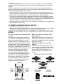
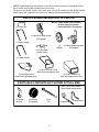
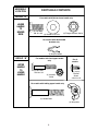
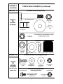
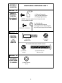
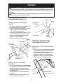
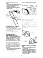
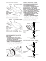
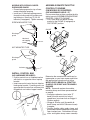
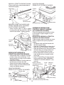
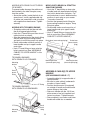
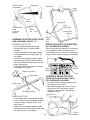
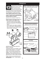
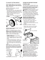
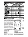
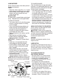
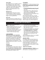
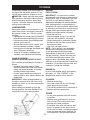
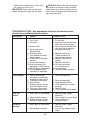
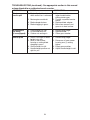
ECONOMY PUSH ROTARY
Lawn Mower
172777 Rev. 2 05.08.03 BY
Printed in U.S.A.
TABLE OF CONTENTS
Safety Rules ......................................... 2
Assembly .............................................. 9
Operation.............................................. 16
Maintenance ......................................... 19
Service and Adjustments...................... 21
Storage ................................................. 22
Troubleshooting .................................... 23
SAFETY RULES
IMPORTANT: This cutting machine is capable of amputating hands and feet and throwing objects. Failure to observe the following safety instructions could result in serious
injury or death.
I. GENERAL OPERATION
Look for this symbol to point out
impor tant safety precautions. It means
CAUTION!!! BECOME ALERT!!!
YOUR SAFETY IS INVOLVED.
• Read, understand, and follow all
instructions on the machine and in the
manual(s) before starting. Be thoroughly
familiar with the controls and the proper
use of the machine before starting.
• Do not put hands or feet near or under
rotating parts. Keep clear of the discharge opening at all times.
• Only allow responsible individuals, who
are familiar with the instructions, to operate the machine.
• Clear the area of objects such as rocks,
toys, wire, bones, sticks, etc., which
could be picked up and thrown by the
blade.
• Be sure the area is clear of other people
before mowing. Stop machine if anyone
enters the area.
• Do not operate the mower when barefoot or wearing open sandals. Always
wear substantial foot wear.
• Do not pull mower backwards unless
absolutely necessary. Always look down
and behind before and while moving
backwards.
• Do not operate the mower without
proper guards, plates, grass catcher or
other safety protective devices in place.
• See manufacturer’s instructions for
proper operation and installation of
accessories. Only use accessories approved by the manufacturer.
• Stop the blade(s) when crossing gravel
drives, walks, or roads.
• Stop the engine (motor) whenever you
leave the equipment, before cleaning the
mower or unclogging the chute.
WARNING: In order to prevent accidental starting when setting up,
transporting, adjusting or making repairs,
always disconnect spark plug wire and
place wire where it cannot contact plug.
WARNING: Engine exhaust, some of its
constituents, and certain vehicle components contain or emit chemicals known to
the State of California to cause cancer and
birth defects or other reproductive harm.
WARNING: Battery posts, terminals and
related accessories contain lead and lead
compounds, chemicals known to the State
of California to cause cancer and birth
defects or other reproductive harm. Wash
hands after handling.
CAUTION: Muffler and other engine
parts become extremely hot during
operation and remain hot after engine has
stopped. To avoid severe burns on contact,
stay away from these areas.
2
• Be alert and turn machine off if children
enter the area.
• Before and while walking backwards,
look behind and down for small children.
• Never allow children to operate the machine.
• Use extra care when approaching blind
corners, shrubs, trees, or other objects
that may obscure vision.
• Shut the engine (motor) off and wait until
the blade comes to complete stop before
removing grass catcher.
• Mow only in daylight or good artificial
light.
• Do not operate the machine while under
the influence of alcohol or drugs.
• Never operate machine in wet grass.
Always be sure of your footing: keep a
firm hold on the handle and walk; never
run.
• Disengage the self-propelled mechanism or drive clutch on mowers so
equipped before starting the engine
(motor).
• If the equipment should start to vibrate
abnormally, stop the engine (motor) and
check immediately for the cause. Vibration is generally a warning of trouble.
• Always wear safety goggles or safety
glasses with side shields when operating
mower.
IV. SERVICE
• Use extra care in handling gasoline and
other fuels. They are flammable and
vapors are explosive.
- Use only an approved container.
- Never remove gas cap or add fuel
with the engine running.
Allow engine to cool before refueling.
Do not smoke.
- Never refuel the machine indoors.
- Never store the machine or fuel
container inside where there is an
open flame, such as a water heater.
• Never run machine inside a closed area.
• Never make adjustments or repairs with
the engine (motor) running. Disconnect
the spark plug wire, and keep the wire
away from the plug to prevent accidental
starting.
• Keep nuts and bolts, especially blade
attachment bolts, tight and keep equipment in good condition.
• Never tamper with safety devices. Check
their proper operation regularly.
• Keep machine free of grass, leaves, or
other debris build-up. Clean oil or fuel
spillage. Allow machine to cool before
storing.
• Stop and inspect the equipment if you
strike an object. Repair, if necessary,
before restarting.
• Never attempt to make wheel height
adjustments while the engine (motor) is
running.
• Grass catcher components are subject
to wear, damage, and deterioration,
which could expose moving parts or
allow objects to be thrown. Frequently
check components and replace with
manufacturer’s recommended parts,
when necessary.
• Mower blades are sharp and can cut.
Wrap the blade(s) or wear gloves, and
use extra caution when ser vicing them.
• Do not change the engine governor setting or overspeed the engine.
II. SLOPE OPERATION
Slopes are a major factor related to slip
and fall accidents which can result in
severe injury. All slopes require extra caution. If you feel uneasy on a slope, do not
mow it.
DO:
• Mow across the face of slopes: never
up and down. Exercise extreme caution
when changing direction on slopes.
• Remove obstacles such as rocks, tree
limbs, etc.
• Watch for holes, ruts, or bumps. Tall
grass can hide obstacles.
DO NOT:
• Do not trim near drop-offs, ditches or
embankments. The operator could lose
footing or balance.
• Do not trim excessively steep slopes.
• Do not mow on wet grass. Reduced footing could cause slipping.
III. CHILDREN
Tragic accidents can occur if the operator
is not alert to the presence of children.
Children are often attracted to the machine
and the mowing activity. Never assume
that children will remain where you last
saw them.
• Keep children out of the trimming area
and under the watchful care of another
responsible adult.
3
CONGRATULATIONS on your purchase of a new Lawn Mower. It has been designed,
engineered and manufactured to give you the best possible dependability and performance.
Should you experience any problems you cannot easily remedy, please contact your
nearest authorized service center. They have competent, well trained technicians and
the proper tools to service or repair this unit.
• Read the SAFETY RULES and this Operator's Manual in its entirety before you attempt to assemble or operate your new lawn mower to insure proper operation and to
prevent injury to yourself and others. Save this manual for future reference.
• Your new lawn mower has been assembled at the factory with the exception of those
parts left unassembled for shipping purposes. To ensure safe and proper operation
of your lawn mower, all parts and hardware you assemble must be tightened securely.
Use the correct tools as necessary to ensure proper tightness.
• All parts such as nuts, washers, bolts, etc., necessary to complete the assembly have
been placed in the parts bag.
TO REMOVE MOWER FROM CARTON
• Remove all loose parts from carton.
• Remove lawn mower housing with care. Avoid touching blade under housing. Always
wear gloves or other protection when working under or lifting mower.
THINGS TO KNOW BEFORE YOU ASSEMBLE OR OPERATE YOUR LAWN
MOWER
Do I have a side or rear discharge lawn
mower?
Look for the grass discharge opening on
your mower. If the opening is on the right
side of the mower housing, it is a side
discharge mower. If the opening is at the
back of the mower housing, it is a rear discharge mower. Only rear discharge lawn
mowers have a grass catcher included with
the mower. Approved grass catchers for
side discharge mowers may be purchased
from your nearest authorized dealer.
Do I have a mulching lawn mower?
Look for the grass discharge opening on
your mower. Raise the discharge guard
(rear door on rear discharge mowers). If
the opening is closed off by a plate, then
your lawn mower is mulcher ready. To
convert to a discharging mower, see the
Operation section of this manual.
What is the right and left side of the
lawn mower?
When right hand (RH) or left hand (LH) is
mentioned in this manual, it means when
you are in the operating position (standing
behind the handle).
What kind of engine is on my lawn
mower?
When learning how to operate your new
lawn mower, you will need to know what
kind of engine powers the mower. A decal
on the engine will indicate the manufacturer and type or brand name of the
engine.
BRIGGS & STRATTON ENGINES
02579-briggs
02579-briggs
02583-bs_classic
02585-bs_sprint
FRONT
02579-briggs
02584-bs_quantum
LEFT
HAND
SIDE
RIGHT
HAND
SIDE
TECUMSEH
ENGINES
HONDA
ENGINES
01737-honda
BACK or REAR
(Operating Position)
®
4
NOTE: Depending upon the features on the lawn mower model you purchased, all the
parts shown may not be included with your mower.
For ease of assembly, aside of your work area, lay out all hardware in the groups shown.
Each step of the assembly instructions will identify the group needed for that step.
PARTS PACKED SEPARATELY IN CARTON
NOTE: Some model lawn mowers
already have the wheels
preassembled to the mower.
(1) Control Bar
(1) Remote Throttle Control
(If Equipped)
(1) Upper Handle
(4)
(4) Wheel Height Adjusters
Wheels
(If Equipped)
(1) Engine Zone
Control Cable
(1) Lower Handle
(1) Grass Catcher Frame
(Rear Discharge mowers only)
(1) Discharge Guard
(Side Discharge models only)
(1) Grass Catcher Bag
(Rear Discharge mowers only)
PARTS BAG CONTENTS NOT SHOWN ACTUAL SIZE
One (1) only of the Starter
Rope Guides shown below:
(1) Upstop
Bracket
(4) Hubcaps
(If Equipped)
Cable
Ties
5
Center Mount
Side Mount
ASSEMBLY
LOCATION
GROUP “A”
LOWER
HANDLE
TO
MOWER
DECK
PARTS BAG CONTENTS
For models with Bolt-on lower handle only
(4) Hex Bolts
3/8-16 x 3/4
(4) Washers 7/8" Dia.
(4) Flange Locknuts 3/8-16
For models with deck handle
brackets only
(2) Hairpin Cotters
GROUP “B”
UPPER
HANDLE
TO
LOWER
HANDLE
For models with fixed upper handle
only
(4) Hex Bolts
3/8-16 x 3/4
(2) Locknuts
1/4-20
For all
models
(1) Upstop
Bracket
Screw
#10-24 x 1/2
For models with folding upper handle only
(2) Handle Bolts
(2) Wing Nuts
6
ASSEMBLY
LOCATION
PARTS BAG CONTENTS (continued)
GROUP "C"
For models with bolt-on wheels only
(4) Shoulder Bolts
WHEELS
TO
MOWER
HOUSING
(4) Locknuts
3/8-16
(2 or 4)
Washers 1-1/4"
Dia.
(4) Spacers
(4) Locknuts
3/8-16
For models with "Quick Adjust" wheel
height adjusters only
(4) Retainer
Springs
(4) Flanged
Locknuts
3/8-16
GROUP "D"
GUARD
TO
MOWER
HOUSING
(Side Discharge
models only)
(4) Washers 1" Dia.
(4) Wheel Adjuster Knobs
For models with bolt-on discharge guard only
(2) Hex Bolts
1/4-20
Screw Mounted
(2) Spacers
(If equipped)
(2) Washers
3/4" Dia.
For models with spring loaded
discharge guard only
(2) Hex Washer Head
Self-tapping Screws
1/4-20 x 3/8
7
(2) Locknuts
1/4-20
Nut Mounted
(2) Locknuts
1/4-20
ASSEMBLY
LOCATION
PARTS BAG CONTENTS CON'T
GROUP "E"
REMOTE
THROTTLE
CONTROL
(If equipped)
TO ENGINE
(1) Diecast Clamp with
#10 x 5/8 Hex Head Screw
(For Briggs Engines only)
NOTE: Tecumseh engines have clamp and screw
preassembled to engine.
(1) Cable Clip with
#10 x 5/8 Hex Head Screw
(For Briggs Classic & Sprint Engines
only with spark plug to front of mower)
(2) Screw 1/4-20 x 3/8
GROUP "F"
CONTROL
CABLE(S)
TO
UPPER
HANDLE
For models without remote throttle control
(1) Locknut
1/4-20
(1) Hex Bolt
1/4-20 x 1-1/2
For models with remote throttle control
(1) Locknuts
1/4-20
(1) Hex Head Screw
1/4-20 x 2-1/8
GROUP "G"
STARTER
ROPE GUIDE
TO HANDLE
(1) Keps Locknut
1/4-20
8
ASSEMBLY
CAUTION: Do not operate this mower without the discharge guard or an entire approved grass catcher in place. These guards are for your protection and are required
by the American National Standards Institute and Consumer Products Safety Commission.
CAUTION: Disconnect spark plug wire from spark plug and place wire where it
cannot come in contact with spark plug.
ASSEMBLE LOWER HANDLE
(REAR DISCHARGE MOWER SHOWN)
(USE HARDWARE GROUP “A”)
Lower handle
MODELS WITH BOLT-ON LOWER
HANDLE
• For ease of lower handle assembly, raise
rear of deck and block securely.
• Position lower handle on deck as shown:
- (20" mowers) cut-off flat forward.
- (22" mowers) arrow down.
• Align holes in handle with holes in deck
as shown and assemble 3/8-16 x 3/4
hex bolts, 7/8" washers and flanged
locknuts. Tighten securely.
• Repeat for opposite side of mower.
7/8" Washers
SQUEEZE
TO INSTALL
Flanged
locknuts
ASSEMBLE UPPER HANDLE
(USE HARDWARE GROUP “B”)
Arrow down
(22" Mowers)
Lower
handle
Hex
bolts
Handle
bracket
mounting pin
Hairpin cotter
MODELS WITH FIXED (NON-FOLDING)
HANDLES
• Position upper handle over lower handle:
- (20" mowers) small hole for mounting
upstop bracket to left hand side.
- (22" mowers) side of handle with four
(4) holes as shown to left hand side.
• Assemble 1/4-20 x 1-1/2 hex bolts and
1/4-20 locknuts. Tighten securely.
Cut-off flat forward
(20" Mowers)
Four (4) holes
(22" Mowers)
MODELS WITH DECK HANDLE
BRACKETS
• Install lower handle onto handle brackets
by squeezing the bottom ends of handle
towards each other until the handle
will slip onto the mounting pins on the
handle brackets.
• Pull handle back to lock in operating
position.
• Install the two (2) hairpin cotters supplied onto the mounting pins.
Upstop
bracket
Hex
bolts
Locknuts
9
Upstop bracket
screw #10-24 x 1/2
MODELS WITH FOLDING UPPER
HANDLE
• Position upper handle over lower handle
with small hole for mounting upstop
bracket to left hand side.
• Assemble handle bolts and wing nuts.
Tighten securely.
(SIDE DISCHARGE MOWER SHOWN)
1-1/4" diameter Washer
(Rear wheels only)
Mower housing
Shoulder
bolt
Spacer
Upstop bracket
Wheel
Upstop
bracket screw
#10-24 x 1/2
3/8-16
Locknut
Wing nuts
Handle bolts
ASSEMBLE UPSTOP BRACKET
(SEE ILLUSTRATION ABOVE)
• Position upstop bracket over hole inside
the left side of upper handle and install
upstop bracket screw
#10-24 x 1/2. Tighten securely.
MODELS WITH "QUICK ADJUST"
WHEEL HEIGHT ADJUSTERS
Look carefully at the four (4) adjuster
assemblies. Notice that there are two (2)
each of two (2) different types.
Type I is for the Right Rear and Left Front
installation.
Type II is for the Right Front and Left Rear
installation.
TYPE I
ASSEMBLE WHEELS
(USE HARDWARE GROUP “C”)
NOTE: Some model mowers do not have
baffles on underside of mower housing.
On models without baffle in front and/or
rear of housing, use the 1-1/4" washers
supplied when you assemble the wheels.
TYPE II
MODELS WITH BOLT-ON WHEELS
Cutting height is determined by assembling wheels in one of four possible positions on the mower housing. All wheels
must be in the same height position for
even cutting.
• For each wheel, assemble shoulder bolt,
wheel and spacer as shown.
• Assemble 1-1/4" diam. washer (if supplied) and 3/8-16 locknut on inside of
mower housing and tighten securely.
ASSEMBLE ADJUSTERS TO MOWER
DECK
• Position appropriate adjuster at each
corner of mower.
• Install each adjuster with adjuster bolt
and tab in deck holes as shown and
secure with 1-1/4" diam. washer (if supplied) and 3/8-16 locknut. Tighten all
adjusters securely.
10
SIDE DISCHARGE MOWERS
Tab hole
INSTALL DISCHARGE GUARD
(SIDE DISCHARGE MODELS ONLY)
(USE HARDWARE GROUP “D”)
If your mower is a rear discharge mower,
go on to “INSTALL CONTROL BAR”.
MODELS WITH BOLT-ON GUARD
NOTE: If your discharge guard has ribbing
as shown in the illustration below, there
are two (2) spacers which must be placed
between guard and mower housing.
• Place discharge guard on top of lawn
mower discharge opening.
• Install two (2) 1/4-20 short hex bolts
through housing and discharge guard.
• Install two (2) 3/4" washers and two
(2)1/4-20 locknuts. Tighten securely.
1-1/4" Washer (If supplied)
Locknuts
TYPE I
Right rear/left front
height adjuster
TYPE II
Right front/left rear height adjuster
Tab hole
REAR DISCHARGE MOWERS
1-1/4" Washer (If supplied)
Tab hole
BOLT-ON GUARD WITH RIBBING
Locknuts
Locknuts
Washers
TYPE I
Right rear/left front
height adjuster
TYPE II
Right front/left rear height adjuster
Spacers
Discharge
guard
ribbing
Tab hole
ASSEMBLE WHEELS TO ADJUSTER
AXLE ARMS
• Secure each wheel with flat washer
and retainer spring or flange locknut (if
equipped with threaded axle).
• Assemble adjustment knobs to adjuster
levers by pressing or tapping lightly.
• If your mower is equipped with hubcaps,
install by pressing or tapping lightly until
hubcap snaps securely over flat washer.
Hex bolts
BOLT-ON GUARD WITHOUT RIBBING
Locknuts
Washers
Axle arm
Wheel
Flat washer
Retainer
spring
Hubcap (If epuipped)
Adjustment
knob
Flange locknut
(If equipped with
threaded axle arm)
Discharge
guard
11
Hex bolts
MODELS WITH SPRING LOADED
DISCHARGE GUARD
• Place discharge guard on top of lawn
mower discharge opening.
• Install two (2) hex self-tapping screws
through housing and into guard mounting bracket or, install two (2) 1/4-20
locknuts (If equipped). Tighten securely.
ASSEMBLE REMOTE THROTTLE
CONTROL TO ENGINE
(ON MODELS SO EQUIPPED)
(USE HARDWARE GROUP “E”)
If your mower does not have a remote throttle
control, go on to “ASSEMBLE ENGINE ZONE
CONTROL CABLE TO ENGINE”.
• First, move lever on remote throttle
control to the CHOKE (if equipped) or
FAST/START position.
SCREW MOUNTED TYPE
CHOKE
Discharge
guard
Hex head
self-tapping
screws
NUT MOUNTED TYPE
FAST/START
Discharge
guard
Locknuts
INSTALL CONTROL BAR
(NO HARDWARE REQUIRED)
• Position control bar so flattened section
with hole is on opposite side of upstop
bracket.
• Insert one end of control bar into hole behind upstop bracket. Carefully push in on
opposite end of control bar and insert into
formed hole on inside of upper handle.
Control
bar
Upstop
bracket
Determine the manufacturer and brand or
type engine on your lawn mower and follow
the appropriate instructions that follow.
MODELS WITH BRIGGS & STRATTON
CLASSIC OR SPRINT AND TECUMSEH
ENGINES
NOTE: Tecumseh engines have cable
mounting clamp and screw preassembled
on engine.
• At engine carburetor, insert wire “Z”
bend of throttle control into hole of
speed lever (use inner hole on Briggs &
Stratton engine).
• (Briggs & Stratton only) Assemble diecast clamp and #10 x 5/8 screw loosely
to engine.
• Position throttle cable under clamp and
push cable towards speed lever until speed
lever touches boss. Hold cable at this po12 sition and tighten clamp screw securely.
BRIGGS & STRATTON ENGINE SHOWN
(Clamp and Screw are preassembled on
Tecumseh engines)
QUANTUM ENGINES SPARK PLUG TO REAR OF MOWER
Speed lever
Throttle
lever
Diecast
clamp
Diecast
clamp
#10 x 5/8
Hex head screw
Hex Head Screw #10 x 5/8
BRIGGS & STRATTON CLASSIC AND
SPRINT ENGINES WITH THE SPARK
PLUG TO FRONT OF MOWER
• Attach throttle cable to side of engine
housing with cable clip and #10 x 5/8 hex
washer head screw. Tighten securely.
Throttle cable
ASSEMBLE ENGINE ZONE
CONTROL CABLE TO ENGINE
(NO HARDWARE REQUIRED)
Follow the appropriate instructions below
for the brand or type of engine on your
lawn mower.
MODELS WITH BRIGGS & STRATTON
CLASSIC OR SPRINT ENGINE
Cable attaches under the brake arm cover,
Throttle
which is opposite the spark plug end of
cable
engine.
• Straighten cable and find the end with
#10 x 5/8
the small plastic fitting.
Hex head screw
• Hook the “Z” bend fitting on inner wire of
cable into hole in brake arm of engine.
• Align the tapered end of the plastic fitting
Cable clip
with the hole in mounting bracket and
push in until fitting snaps into place.
MODELS WITH BRIGGS &
• Route cable below crossbar portion of
STRATTON QUANTUM ENGINES
lower handle and up to upper handle
• Slide throttle lever on engine to CHOKE
control bar.
position (away from spark plug). Push
• Hook “Z” bend fitting on inner wire into
gently beyond first stop to lock in detent
hole in control bar (See “ASSEMBLE
(CHOKE position).
CABLES TO UPPER HANDLE” in this
• Insert wire “Z” bend of throttle cable into
manual).
throttle lever hole from top side.
Engine cable clip
Brake Mounting
• Secure throttle cable to engine with
(rearward spark plug
arm
bracket
diecast clamp and #10 x 5/8 hex head
Brake
models only)
cover
screw and tighten securely.
arm
QUANTUM ENGINES SPARK PLUG TO FRONT OF MOWER
Throttle cable
Hex
Head
Screw
#10 x 5/8
"Z" Fitting
Throttle
lever
Diecast clamp
Small plastic fitting
Hex head screw #10 x 5/8
(rearward spark plug models only)
13
MODELS WITH BRIGGS & STRATTON
QUANTUM ENGINES
• Hook the “Z” bend fitting on inner wire
of cable (end with tapered plastic fitting)
into hole in brake lever of engine. Correct brake lever to use is determined by
position of spark plug on your mower
- forward or rearward.
• Position the tapered plastic fitting into
the mounting bracket on engine. Snap
fitting into place.
• Route cable under crossbar portion of
lower handle and up to upper handle
control bar.
• Hook “Z” bend fitting on inner wire into
hole in control bar (See “ASSEMBLE
CABLES TO UPPER HANDLE”).
MODELS WITH SPARK PLUG TO REAR
OF MOWER
To prevent cable damage, the cable must
be attached to the side of engine, away
from the muffler.
• Above the muffler, locate the hole in engine shroud. Install supplied cable clip
on cable and assemble to side of engine
with supplied hex head screw. Tighten
securely.
MODELS WITH TECUMSEH ENGINE
• Straighten cable and find the end with
the small tapered plastic fitting.
• Hook the “Z” bend fitting on inner wire of
cable into hole as shown.
• Align the tapered end of the plastic fitting
with the hole in the mounting bracket
Brake lever
and push in until fitting snaps into place. Brake lever (rearward spark plug)
(forward
spark
• Route cable under crossbar portion of
plug)
lower handle and up to upper handle
control bar.
• Hook “Z” bend fitting on inner wire into
hole in control bar (See “ASSEMBLE
CABLES TO UPPER HANDLE” in this
manual).
TECUMSEH ENGINES
WITH SPARK PLUG FORWARD
Mounting bracket
(rearward spark plug)
Mounting
bracket
Small
plastic
fitting
Mounting bracket
(forward spark plug)
ASSEMBLE CABLE(S) TO UPPER
HANDLE
(USE HARDWARE GROUP “F”)
• Assemble cable(s) to opposite side of
upstop bracket.
• Be sure to route cable(s) underneath
crossbar of lower handle.
“Z” Fitting
• Position throttle control (if equipped)
TECUMSEH ENGINES
on outside of handle and zone control
WITH SPARK PLUG REARWARD
square fitting on the inside.
• Secure to handle with the 1/4-20 machine screw or hex bolt supplied and
locknut as shown. Tighten securely.
• Secure cable(s) to crossbar and lower
handle with cable ties as needed.
“Z” Fitting
Mounting
bracket
Small
plastic
fitting
14
Throttle control
(If equipped)
Control bar
Control bar
Upper
handle
1/4-20
Locknut
1/4-20 Machine
screw
or hex bolt
supplied
Rope guide
1/4-20
Keps locknut
Cable
ties
Lower handle
crossbar
Engine
starter
rope
ASSEMBLE STARTER ROPE GUIDE
(USE HARDWARE GROUP “G”)
SPARK PLUG BOOT (IF EQUIPPED)
CENTER MOUNT TYPE
• Install threaded end of rope guide
through hole in top of lower handle
crossbar.
• Loosely assemble 1/4-20 keps locknut
on threaded portion of rope guide. Do
not tighten.
• Hold control bar against upper handle
and slowly pull starter rope out and up
over lower handle crossbar and slip into
loop of rope guide.
• Push rope guide down against crossbar
and tighten nut securely.
(NO HARDWARE REQUIRED)
On some model lawn mowers a spark plug
boot is packed loose in the parts bag. If
your model has one, install it on spark plug
wire and then reconnect plug to spark plug.
Spark
plug wire
Spark
plug
Engine starter rope
Boot
Rope guide
ASSEMBLE GRASS CATCHER
(REAR DISCHARGE MODELS ONLY)
(NO HARDWARE REQUIRED)
• Put grass catcher frame into grass bag
with rigid part on bottom.
• Slip vinyl bindings over frame. If bindings are too stiff, hold them in warm
water for a few minutes. Allow bag to
dry before using.
Lower handle
1/4-20 Keps locknut
Catcher frame
SIDE MOUNT TYPE
• Put threaded end of rope guide through
hole in side of upper handle above lower
handle crossbar. Secure with 1/4-20
keps locknut.
• Hold control bar against upper handle
and slowly pull starter rope out until rope
will slip into loop of rope guide.
15
Vinyl binding
Frame
opening
OPERATION
The operation of any lawn
mower can result in foreign
objects thrown into the
eyes, which can result in
severe eye damage. Always
wear safety glasses or eye shields while
operating your lawn mower or performing
any adjustments or repairs. We recommend standard safety glasses or a wide
vision safety mask worn over spectacles.
BRIGGS & STRATTON CLASSIC or SPRINT
ENGINE MOUNTED SPEED CONTROL
Spark
plug
HOW TO USE YOUR LAWN MOWER
ENGINE SPEED CONTROL
MODELS WITH REMOTE THROTTLE
Engine speed is controlled by the throttle
control located on the upper handle.
• Move lever forward to FAST engine
speed for starting and better bagging.
• Move lever backward for SLOW engine
speed.
• Some models have engines equipped
with a choke feature. Move the lever all
the way forward to the CHOKE position
when starting a cold engine.
FAST
Primer (if equipped)
Engine
speed
control lever
BRIGGS & STRATTON QUANTUM
ENGINE MOUNTED SPEED CONTROL
Engine speed control lever
Primer (if
equipped)
SLOW
CHOKE
(START)
TECUMSEH
ENGINE MOUNTED SPEED CONTROL
Remote
throttle
control
MODELS WITH ENGINE MOUNTED
SPEED CONTROL
The engine speed is controlled by a lever
located at the carburetor on the engine.
HIGH or FAST position is for starting
engine, normal cutting and better grass
bagging. LOW or SLOW position is for
light cutting, trimming and fuel economy.
MODELS WITH FIXED SPEED ENGINES
Engine speed was set at the factory for
optimum performance. Engine speed is
not adjustable.
16
Engine speed
control lever
Primer (if equipped)
TO ADJUST CUTTING HEIGHT
Adjust cutting height to suit your requirements. Medium position is best for most
lawns. Raise wheels for low cut and lower
wheels for high cut.
MODELS WITH MANUAL ADJUST
BOLT-ON WHEELS
• Remove wheel, bolt, and hardware and
reassemble in desired adjustment hole.
• Reinstall wheel components in the same
order as they were before removal.
Tighten securely.
• Make sure all wheels are at the same
height.
Flat washer
OPERATOR PRESENCE ENGINE
CONTROL BAR
Your lawn mower is equipped with an operator presence engine control bar which
requires the operator to be positioned
behind the lawn mower handle in order to
start and operate the lawn mower.
CAUTION: Federal regulations require
an engine control to be installed on this
lawn mower in order to minimize the
risk of blade contact injury. Do not under
any circumstances attempt to defeat the
function of the operator control. The blade
turns when the engine is running.
GRASS CATCHER (REAR
DISCHARGE MODELS ONLY)
TO ATTACH GRASS CATCHER
• Open rear door. Place frame onto
formed tabs on hinge bracket.
Bolt
• Release rear door and allow to rest on
catcher.
3/8-16
Spacer
Locknut TO REMOVE GRASS CATCHER
• Simply open rear door and lift grass
catcher up and away from mower.
MODELS WITH "QUICK ADJUST" WHEEL
HEIGHT ADJUSTERS
NOTE: For shipping purposes, the rear
Rear door
wheels on your lawn mower may not be
adjusted to the same position as the front
wheels. Before operating mower, adjust all
wheels to the same cutting height.
• Raise wheels for low cut and lower
wheels for high cut.
• Adjust cutting height to suit your requirements. Medium position is best for most
lawns.
• To change cutting height, squeeze adHinge bracket
formed tabs
juster lever toward wheel. Move wheel
up or down to suit your requirements.
Be sure all wheels are in the same setCatcher frame
ting.
NOTE: Adjuster is properly positioned
CAUTION: Under normal usage, the
when plate tab inserts into hole in lever.
catcher material is subject to deterioration
Also, 9-position adjusters (if so equipped)
and wear and should, therefore, be
allow lever to be positioned between the
checked frequently for replacement. Any
plate tabs.
replacement catcher should be checked
to ensure compliance with original
LOWER WHEELS
Plate tab
manufacturer's specifications.
FOR HIGH CUT
CAUTION: Do not run lawn mower
without the discharge guard (rear door),
approved grass catcher or clipping
deflector in place. Never attempt to
operate mower with the discharge guard
(rear door) removed or propped open.
RAISE WHEELS FOR LOW CUT
Lever
17
Wheel
• Hold operator presence control bar
down against handle.
Read engine manual packed with your unit.
•
Pull starter handle quickly. Do not allow
FILL ENGINE WITH OIL
starter
rope to snap back.
Your lawn mower is shipped without oil in
•
For
engines
equipped with choke, slowly
the engine.
move
engine
speed control lever to
• Be sure mower is level and area around
FAST position after engine starts.
oil fill is clean.
•
To STOP engine, release operator pres• Remove engine oil filler plug (oil fill cap/
ence
engine control bar.
dipstick on models so equipped).
NOTE:
For engines with a primer, it may be
• Slowly add oil. For type and grade of
nec
es
sary
to repeat priming steps in cooler
oil to use, see “ENGINE” in the Mainteweather.
In
warmer weather, overpriming
nance section of this manual.
may cause flooding and engine will not start.
• Fill to the top of slot in filler hole (to
If you do flood engine, wait a few minutes
“FULL” line on dipstick on models so
before attempting to start and DO NOT
equipped). Do not overfill.
repeat priming steps.
• Replace plug (oil fill cap/dipstick on
Operator presence
models so equipped) and tighten.
Recoil
• Check oil level before each use. Add oil control bar
starter
handle
as needed.
(center
Recoil starter
• To change oil, see “TO CHANGE ENmount
GINE OIL” in the Maintenance section of handle (side
type)
mount type)
this manual.
FILL GASOLINE TANK
MOWING TIPS
• Fill gasoline tank with fresh, clean, un• For most cutting conditions and better
leaded gasoline. DO NOT USE PREbagging performance, the engine speed
MIUM GASOLINE. BE CAREFUL NOT
should be set in the FAST position.
TO OVERFILL TANK.
•
Under certain conditions, such as when
WARNING: Experience indicates that
mowing very tall grass, raise the mower
alcohol blended fuels (called gasohol or
height on the first cut to reduce pushing
using ethanol or metha nol) can at tract
effort, to avoid overheating the engine, and
mois ture which leads to sepa ra tion and
to avoid leaving clumps of grass clippings.
formation of acids during storage. Acidic gas
Make the second cut to the desired height.
can damage the fuel system of an engine
•
For extremely heavy cutting, reduce the
while in storage. To avoid engine problems,
width of cut.
the fuel system should be emptied before
•
For side discharge lawn mowers, cut in a
storage of 30 days or longer. Drain the fuel
coun
terclockwise direction, starting at the
tank, start the engine and let it run until fuel
outside
of the area to be cut, in order to
lines and carburetor are empty. Use fresh
spread
grass
clippings more evenly and
fuel next season. See Storage Instructions
to
put
less
load
on the engine. To keep
for additional information. Never use engine
clippings off of walkways, flower beds, etc.,
or carburetor cleaner products in fuel tank or
make the first cuts in a clockwise direction.
permanent damage may occur.
• When using a rear discharge lawn
mower in moist, heavy grass, clumps
TO START ENGINE
of cut grass may not enter the grass
CAUTION: The mower blade rotates
catcher. Reduce ground speed (pushing
whenever the engine is running.
speed) and/or run the lawn mower over
• Move engine speed control to FAST
the area a second time.
position or to CHOKE/START position
•
If a trail of grass clipping is left on the right
on models equipped with choke feature.
side
of a rear discharge lawn mower, mow
• If your mower has a primer, to start a
in
a
clockwise
direction with a small overlap
cold engine, push primer the number of
to
collect
the
clippings
on the next pass.
times as instructed in the engine manual
• Pores in cloth grass catchers can bepacked with your mower. Use a firm
come filled with dirt and dust with use
push. This step is not usually necessary
and the catcher will collect less grass.
when starting an engine which has
To prevent this, regularly hose catcher
already run for a few minutes.
off with water and let dry before use.
18
BEFORE STARTING ENGINE
MAINTENANCE
GENERAL RECOMMENDATIONS
LUBRICATION CHART
The warranty on this lawn mower does not
cover items that have been subjected to op➀ Wheel
adjuster (on
erator abuse or negligence. To receive full
each wheel)
value from the warranty, operator must maintain mower as instructed in this manual.
Some adjustments will need to be made
➁ Engine oil
periodically to properly maintain your unit.
All adjustments in the Service and Adjustments section of this manual should be
➀ Side dischecked at least once each season.
charge mower
• Once a year, replace the spark plug,
guard hinge rod
clean or replace air filter element, and
check blade for wear. A new spark plug
➀ Rear disand clean/new air filter element assures
charge
mower
proper air-fuel mixture and helps your
rear
door
engine run better and last longer.
hinge
rod
• Follow the Maintenance Schedule in this
manual.
➀ Handle bracket mounting pins
BEFORE EACH USE
• Check engine oil level.
➀ Spray lubricant
• Check for loose fasteners.
LUBRICATION
➁ See “ENGINE” in Maintenance section.
Keep unit well lubricated.
of the self-lubricating bearings. If you feel
IMPORTANT: Do not oil or grease plastic
they must be lubricated, use only a dry,
wheel bearings. Viscous lubricants will
attract dust and dirt that will shorten the life powdered graphite type lubricant sparingly.
19
TO SHARPEN BLADE
Always observe safety rules when perform- Care should be taken to keep the blade
balanced. An unbalanced blade will cause
ing any maintenance.
excessive vibration and eventual damage
TIRES
• Keep tires free of gasoline, oil, or insect to lawn mower and engine.
control chemicals which can harm rubber. • The blade can be sharpened with a file
or on a grinding wheel. Do not attempt
• Avoid stumps, stones, deep ruts, sharp
to sharpen while on the mower.
objects and other hazards that may
•
To check blade balance, drive a nail into
cause tire damage.
a beam or wall. Leave about one inch of
BLADE CARE
the straight nail exposed. Place center
For best results, mower blade must be kept
hole of blade over the head of the nail. If
sharp. Replace bent or damaged blades.
blade is balanced, it should remain in a
TO REPLACE BLADE
horizontal position. If either end of the
• Turn lawn mower on it’s side. See engine
blade moves downward, sharpen the
manual for proper direction of turning
heavy end until the blade is balanced.
over the engine.
• Use a wood block between blade and
GRASS CATCHER (IF SO EQUIPPED)
mower housing to prevent blade from
Grass catcher may be hosed with water
turning when removing blade bolt.
but must be dry when used.
• Protect your hands with gloves and/or
CAUTION: Under normal usage, the
wrap blade with heavy cloth.
catcher material is subject to deterioration
• Remove blade bolt, lock washer and flat and wear and should therefore be checked
washer.
to ensure compliance with original
• Remove blade and blade adapter.
manufacturer specifications.
• Inspect the key inside blade adapter.
ENGINE
Replace adapter if damaged.
IMPORTANT: Blade bolt is grade 8 heat
Read the maintenance section of your
treated.
engine manual.
• Install new or sharpened blade with
LUBRICATION
trailing edge up toward the engine.
• Position blade on blade adapter. Align
Change the oil after the first two hours of
the two (2) holes in blade with raised
operation and every 25 hours thereafter or
lugs of adapter.
at least once a year if the lawn mower is
• Reassemble blade bolt, lock washer
not used for 25 hours in one year. Refer to
and flat washer into blade adapter and
engine manual.
crankshaft in exact order as shown.
• Position block of wood between blade
TO CHANGE ENGINE OIL
and mower housing.
(SEE ENGINE MANUAL)
• Tighten blade bolt securely. Recom• Be sure mower is on a level surface.
mended tightening torque is 35-40 ft. lbs. • Oil will drain more freely when warm.
NOTE: We do not recommend sharpening • Catch oil in a suitable container.
the blade - but if you do, be sure the blade • For engines without dipstick, remove
is balanced.
bottom oil drain plug.
Crankshaft • For engines with oil fill cap/dipstick,
Blade adapter
keyway
remove bottom drain plug or remove enKey
gine oil cap and turn mower on its side.
Lockwasher
• After oil has drained completely, replace
Blade
oil drain plug and tighten securely.
• Refill engine with oil. Pour slowly. Do
not overfill.
• Fill to top of slot inside of filler hole or
to “FULL” line on dipstick on models so
Crank
equipped. Keep oil at proper level.
LAWN MOWER
Blade
bolt Hardened
Trailing edge
washer
shaft
Blade adapter
20
AIR FILTER
Your engine will not run properly and may
be damaged by using a dirty air filter.
Clean the element after every 25 hours
of operation, more often if lawn mower is
used in very dusty, dirty conditions.
See the maintenance section of your
engine manual.
SPARK PLUG
Change the spark plug once a year to
make the engine run better and easier
to start. Set spark plug gap according to
engine manual specifications.
MUFFLER
Inspect and replace corroded muffler as it
could create a fire hazard and/or damage.
CLEANING
IMPORTANT: For best performance, keep
mower housing free of grass build-up and
trash. Clean the underside of your mower
after each use.
• Clean the underside of your lawn mower
by scraping to remove buildup of grass
and trash.
• Clean engine often to keep trash from
accumulating. A clogged engine runs
hotter and shortens engine life.
• Keep finished surfaces and wheels free
of all gasoline, oil, etc.
We do not recommend using a garden
hose to clean your lawn mower unless the
electrical system, muffler, air filter, and
carburetor are covered to keep water out.
Water in engine can shorten engine life.
SERVICE AND ADJUSTMENTS
CAUTION: Before performing any
service or adjustments• Release operator presence control bar.
• Make sure the blade and all moving
parts have completely stopped.
• Disconnect spark plug wire from spark
plug and place wire where it cannot
come in contact with spark plug.
LAWN MOWER
REAR DEFLECTOR (IF EQUIPPED)
The rear deflector, attached between the
rear wheels of your mower, is provided to
minimize the possibility that objects will
be thrown out of the rear of the mower
into the operator mowing position. If the
deflector becomes damaged, it should be
replaced.
ENGINE
CARBURETOR
The carburetor has been preset at the factory and adjustment should not be necessary. However, minor adjustment may be
required to compensate for differences in
fuel, temperature, altitude or load.
• The air filter must be assembled to the
carburetor when running engine.
• Best carburetor adjustment is obtained
when fuel tank is 1/4 full.
• In order for the engine to run, the operator presence control bar must be held
in the operating position. Therefore,
and assistant will be required to hold
the control bar in the operating position
when making final adjustment to the
carburetor.
See the adjustment section of your engine
manual for further instructions.
ENGINE SPEED
The engine speed has been factory set.
Do not attempt to increase engine speed
as it may result in personal injury. If you
believe the engine is running too fast
or too slow, take your lawn mower to an
authorized engine service center for repair
and adjustment.
THROTTLE CONTROL
If it becomes necessary to adjust or
replace the throttle control, see the adjustment section of your engine manual.
21
STORAGE
Immediately prepare your lawn mower for
storage at the end of the season or if the
unit will not be used for 30 days or more.
CAUTION: Never store the lawn mower
with gasoline in the tank inside a building
where fumes may reach an open flame
or spark. Allow the engine to cool before
storing in any enclosure.
ENGINE
FUEL SYSTEM
IMPORTANT: It is important to prevent
gum deposits from forming in essential fuel
system parts such as carburetor, fuel filter,
fuel hose, or tank during storage. Also,
experience indicates that alcohol blended
fuels (called gasohol or using ethanol or
methanol) can attract moisture which leads
LAWN MOWER
When lawn mower is to be stored for a pe- to separation and formation of acids during
riod of time, clean it thoroughly, remove all storage. Acidic gas can damage the fuel
systme of an engine while in storage.
dirt, grease, leaves, etc. Store in a clean,
• Drain the fuel tank.
dry area.
• Clean entire lawn mower (See “CLEANING” • Start the engine and let it run until the
fuel lines and carburetor are empty.
in the Maintenance section of this manual).
• Never use engine or carburetor cleaner
• Lubricate as shown in the Maintenance
products in the fuel tank or permanent
section of this manual.
damage may occur.
• Be sure that all nuts, bolts, screws, and
•
Use fresh fuel next season.
pins are securely fastened. Inspect
NOTE:
Fuel stabilizer is an acceptable
moving parts for damage, breakage and
alternative in minimizing the formation
wear. Replace if necessary.
of fuel gum deposits during storage.
• Touch up all rusted or chipped paint
Add stabilizer to gasoline in fuel tank or
surfaces; sand lightly before painting.
storage container. Always follow the mix
ratio found on stabilizer container. Run
HANDLE STORAGE
engine at least 10 minutes after adding
(HANDLE BRACKET MODELS ONLY)
stabilizer to allow the stabilizer to reach the
Your handle may be folded for storage as
carburetor. Do not drain the gas tank and
shown.
carburetor if using fuel stabilizer.
• Squeeze the bottom ends of lower
handle towards each other until handle
ENGINE OIL
clears the handle brackets and swing
handles forward over mower.
Drain oil (with engine warm) and replace
• Loosen upper handle mounting hardwith clean oil. (See “ENGINE” in the
ware enough to allow upper handle to be Maintenance section of this manual).
folded back.
IMPORTANT: When folding handles for
CYLINDER
storage or transportation, be sure to fold
• Remove spark plug.
handles as shown or you may damage the • Pour one ounce (29 ml) of oil through
control cables.
spark plug hole into cylinder.
When setting you handles up from the
• Pull starter handle slowly to distribute oil.
storage position, the lower handle will au• Replace with new spark plug.
tomatically lock into mowing position.
OTHER
• Do not store gasoline from one season
to another.
• Replace your gasoline can if your can
starts to rust. Rust and/or dirt in your
gasoline will cause problems.
• If possible, store your unit indoors and
cover it to protect it from dust and dirt.
• Cover your unit with a suitable protective
cover that does not retain moisture. Do
not use plastic. Plastic cannot breathe,
22
which allows condensation to form and
will cause your unit to rust.
IMPORTANT: Never cover mower while
engine and exhaust areas are still warm.
CAUTION: Never store the lawn mower
with gasoline in the tank inside a building
where fumes may reach an open flame or
spark. Allow the engine to cool before storing in any enclosure.
TROUBLESHOOTING - See appropriate section in this manual unless
directed to an authorized service center.
PROBLEM
Does not start
CAUSE
CORRECTION
1. Dirty air filter.
2. Out of fuel.
3. Stale fuel.
4. Water in fuel.
5. Spark plug wire is
disconnected.
6. Bad spark plug.
7. Loose blade or broken
blade adapter.
8. Control bar in released
position.
9. Control bar defective.
10. Fuel valve lever (if so
equipped) in OFF position.
11. Weak battery (if equipped).
12. Disconnected battery
connector (if equipped).
Loss of power
Poor cut –
uneven
1. Rear of lawn mower
housing or cutting blade
dragging in heavy grass.
2. Cutting too much grass.
3. Dirty air filter.
4. Buildup of grass, leaves,
and trash under mower.
5. Too much oil in engine.
6. Walking speed too fast.
1. Worn, bent or loose blade.
2. Wheel heights uneven.
3. Buildup of grass, leaves
and trash under mower.
Excessive
vibration
1. Worn, bent or loose blade.
2. Bent engine crankshaft.
23
1. Clean/replace air filter.
2. Fill fuel tank.
3. Drain fuel tank and refill tank
with fresh, clean gasoline.
4. Drain fuel tank and refill tank
with fresh, clean gasoline.
5. Connect wire to plug.
6. Replace spark plug.
7. Tighten blade bolt or
replace blade adapter.
8. Depress control bar to
handle.
9. Replace control bar.
10. Turn fuel valve lever
to the ON position.
11. Charge battery.
12. Connect battery to engine.
1. Raise cutting height.
2. Raise cutting height.
3. Clean/replace air filter.
4. Clean underside of mower
housing.
5. Check oil level.
6. Cut at slower walking speed.
1. Replace blade. Tighten
blade bolt.
2. Set all wheels at same height.
3. Clean underside of
mower housing.
1. Replace blade. Tighten
blade bolt.
2. Contact a qualified service
center.
TROUBLESHOOTING (continued) - See appropriate section in this manual
unless directed to an authorized service center.
PROBLEM
CAUSE
CORRECTION
Starter rope
hard to pull
1. Engine flywheel brake is on 1. Depress control bar to
when control bar is released.
upper handle before
pulling starter rope.
2. Bent engine crankshaft.
2. Contact a qualified service
center.
3. Blade adapter broken.
3. Replace blade adapter.
4. Blade dragging in grass.
4. Move lawn mower to cut
grass or to hard surface.
Grass catcher
not filling
(If so equipped)
1. Cutting height too low.
2. Lift on blade worn off.
3. Catcher not venting air.
1. Raise cutting height.
2. Replace blade.
3. Clean grass catcher.
Hard to push
1. Grass is too high or wheel
height is too low.
2. Rear of lawn mower
housing or cutting blade
dragging in grass.
3. Grass catcher too full.
4. Handle height position not
right for you.
1. Raise cutting height.
24
2. Raise rear of lawn mower
housing one (1) setting
higher.
3. Empty grass catcher.
4. Adjust handle height to suit.