1
SMW-HR
Wall Mount High Resolution Weighing
Indicator/Controller
User Manual
www.mantracourt.co.uk
SMW-HR Surface Mount Amplifier Manual
Contents Pages
Chapter 1 Introduction to SMW-HR ............................................................................................... 2
Chapter 2 Installing the SMW-HR .................................................................................................. 4
Environmental Requirements ........................................................................................................... 5
Conditions .................................................................................................................................. 5
Terminal Connections .................................................................................................................... 5
Chapter 3 The SMW-HR Controls and Parameters .............................................................................. 7
The Configurable Parameters........................................................................................................... 8
Section 1 User/Engineer - Configurable Parameters ............................................................................... 8
Section 2 Calibrators - Configurable Parameters ................................................................................... 9
Chapter 4 Strain Gauge Input to the SMW-HR.................................................................................. 12
The Strain Gauge Input ................................................................................................................. 12
Calibration ................................................................................................................................ 13
4 Point Linearisation .................................................................................................................... 13
Chapter 5 Analogue Outputs ...................................................................................................... 15
Output Scaling............................................................................................................................ 15
Method of Calculating OP LO and OP Hi from any known output values ....................................................... 15
Calibration ................................................................................................................................ 16
Chapter 6 Relay Output Module .................................................................................................. 17
Module Functions ........................................................................................................................ 17
Set Points (SP) ............................................................................................................................ 17
In Flight Compensation ................................................................................................................. 17
Hysteresis (HYS) .......................................................................................................................... 18
Output Action (Action) .................................................................................................................. 18
Latching Outputs (LAtCH) .............................................................................................................. 18
Figure 6.1 LR1 Module .................................................................................................................. 18
Chapter 7 The Communications Port ............................................................................................ 19
Introduction .............................................................................................................................. 19
Serial Communication Protocol ....................................................................................................... 19
MANTRABUS Format - selected when CP is 128..................................................................................... 19
Operation ................................................................................................................................. 19
Updating................................................................................................................................... 19
Communications Commands ........................................................................................................... 20
Command 1
Request for all data: ................................................................................................. 20
Response to Command 1 ............................................................................................................... 21
COMMAND 2 REQUEST DISPLAY DATA ................................................................................................. 22
Response to Command 2 ............................................................................................................... 22
COMMANDS 4 TO 34: Write data to SMW-HR Parameter .......................................................................... 22
Response to COMMAND 4 to 34 ........................................................................................................ 22
Register Allocation ...................................................................................................................... 24
ASCII Protocol ............................................................................................................................ 26
List of commands ........................................................................................................................ 28
SMW-HR Printer Interface .............................................................................................................. 29
Additional Mnemonics for the Printer Operation: .................................................................................. 29
Chapter 8 Trouble Shooting Guide ............................................................................................... 33
Chapter 9 SMW-HR Specifications ................................................................................................ 34
The Communications Port Data ....................................................................................................... 35
SMW-HR Order Codes .................................................................................................................... 36
Optional Modules ........................................................................................................................ 36
SMW-HR Accessories ..................................................................................................................... 36
Instrument Setup Record Sheet ....................................................................................................... 37
W A R R A N T Y .......................................................................................................................... 38
Mantracourt Electronics Limited SMW-HR User Manual
1
Chapter 1 Introduction to SMW-HR
The Surface Mount Intelligent Strain Gauge Amplifier SMW-HR with an 6 digit 12.7mm, LCD display is a compact
microprocessor based unit specifically designed to monitor and control weighing applications.
Its flexibility of design allows for the connection of most strain gauges, pressure or strain gauges over a wide range
of sensitivity's.
Housed in a light grey, ABS case, it is sealed to IP65 standard to meet most environmental conditions, or as a DIN
Rail Mounting module with a separate stainless steel panel mounting display and keypad.
The unit offers the following facilities:A simple auto calibration of the highest and lowest weights required, an easy auto tare setting and peak hold
facility. A password facility gives protection to setup parameters.
DC analogue outputs of 4-20mA and 0-10V are standard with full scaling over any desired range and the ability to
invert these outputs if required.
Two passwords - user and calibrator, 4 point linearisations with multiple strain gauge calibrations stored if required.
Gain sensitivity is selectable via Link & Keypad between 1.25 and 30mV/V.
Several 'plug in' options are available. An optional relay output module provides for 2 set points and hysteresis can
be applied to both set points together with In Flight compensation. Relays can be inverted and latched. All these
facilities being set digitally in real engineering terms. Both relay and analogue outputs have a high level of isolation.
Optional communications modules provide for 20mA noise immune current loop, RS232 or RS485 connections to a
PC, PLC or main frame. This allows for the input variable to be viewed and any setup parameters changed.
Multiple 20mA SMW-HRs can be connected via an IF25 current loop to RS232 interface which, when included, allows
for an expansion of up to 250 SMW-HRs.
The RS232 port is available for Time/Data or data only printers to be used, logging all desired activities.
Baud speeds between 300 and 19200 are programmable.
The power supply module is available for 220/240V AC and 110/120V AC or 9-32 and 24/48V DC.
2
Mantracourt Electronics Limited SMW-HR User Manual
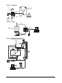
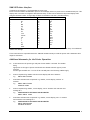
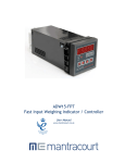
Figure 1.1 Bagging
Bagging
Hopper suspended
on 3 Strain Gauges
(only 2 shown)
Printer
Control
Output
SM
S P1
S P2
F N1
F N2
tonne
F1
GROSS
F2
NET
F3
TARE
F4
100
kg
Input
PLC
Analogue
Output
10000
Remote
Indicator
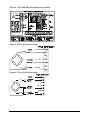
Figure 1.2 Drum
Control Output
RS232
or 20mA Loop
SM
Platform placed
on 4 Strain Gauges
SP1
SP2
FN1
FN2
tonne
F1
GROSS
F2
NET
F3
TARE
F4
Input
Figure 1.3 Mixing Control by PC
RECIPEMIXING/ INGREDIENTS
Mantracourt Electronics Limited SMW-HR User Manual
3
Chapter 2 Installing the SMW-HR
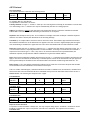
In order to maintain compliance with the EMC Directive 2004/108/EC the following installation recommendations
should be followed.
Inputs:
Use individually screened twisted multipair cable. (e.g. FE 585 - 646)
The pairs should be :
pins 1 & 6
pins 2 & 5
pins 3 & 4
Terminate all screens at pin 1 of the input. The screens should not be
connected at the transducer end of the cables.
Comms Port:
Use individually screened twisted multipair cable. (e.g. FE 118-2117)
The pairs should be:
-Tx & +Tx
-Rx & +Rx
Terminate screens at pin 1 of the input .
The screens should not be connected at the host port.
Analogue
Output:
Use screened twisted pair cable. (e.g. RS 626-4761)
Terminate screen at pin 1 of the input.
The screen should not be connected at the host port.
Pin 1 of the input should be connected to a good Earth. The Earth connection
should have a cross-sectional area sufficient enough to ensure a low
impedance, in order to attenuate RF interference.
Cable Information (For Reference only)
Country
UK
Supplier
Farnell
Part No
118-2117
UK
Farnell
585-646
UK
RS
626-4761
4
Description
Individually shielded twisted multipair cable (7/0.25mm)- 2 pair
Tinned copper drain. Individually shielded in polyester tape.
Diameter: 4.1mm
Capacitance/m: core to core 115 pF & core to shield 203 pF
Individually shielded twisted multipair cable (7/0.25mm)- 3 pair
Tinned copper drain. Individually shielded in polyester tape.
Diameter: 8.1mm
Capacitance/m: core to core 98 pF & core to shield 180 pF
Braided shielded twisted multipair cable (7/0.2mm)- 1 pair
Miniature- twin -round Diameter: 5.2 mm
Capacitance/m: core to core 230 pF & core to shield 215 pF
Mantracourt Electronics Limited SMW-HR User Manual
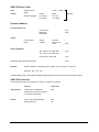
Environmental Requirements
SMW-HR units can operate in any industrial environment provided the following limits are not exceeded at the point
of installation:
Operating
10 ºC to 50 ºC
Temperature/Humidity
95 % non condensing
Storage Temperature
-20 ºC to +70 ºC
Two power supply options are available
Units can operate from the following:220/240V AC, 50/60Hz 10W
110V AC, 50/60Hz 10W
LS1
110/240
9-30V DC, 10W
LS3
(Running current 300 - 530mA Dependent upon
module configuration)
(start up current - 3Amps for 20mS)
Conditions
Watts
Power in
12 : 24V
I. SMW and LP1 with 1 x 350R strain gauge connected, and a 4-20mA
analogue output providing 20mA into a short circuit
2.24
II. With relay module fitted, add
0.58W 0.65W
III. With RS232 module fitted- no device connected, add
0.07W 0.09W
IV. For each additional 350R strain gauge, add
0.38W 0.48W
2.88
Note: Maximum number of strain gauges = 6 x 350R or equivalent
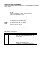
Terminal Connections
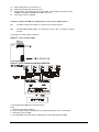
Connection between the SMW-HR unit and input/output signals, including power supplies, are made via 2.5mm field
terminal blocks inside the unit.
Access to the terminals is made through glands in the bottom of the case.
(See Figure 2.1)
Mantracourt Electronics Limited SMW-HR User Manual
5
Figure 2.1 The SMW-HR Field Connection Terminals
Figure 2.2 The 6 Wire Strain Gauge
Figure 2.3 The 4 Wire Strain Gauge
6
Mantracourt Electronics Limited SMW-HR User Manual
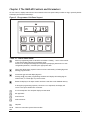
Chapter 3 The SMW-HR Controls and Parameters
All user controls, displays and indicators are mounted on the front panel which provides a 6 digit, optionally backlit
LCD display and 8 flush mounted keys .
Figure 3.1 Programmer Unit Panel Layout
SM
SP1
SP2
II
FN1
FN2
tonne
R
F1
F2
F3
F4
Table 3.1 Control Panel Guide
d
When in programming mode it should be noted that a flashing -- cursor at the bottom
of the selected digit indicates programming mode.
Used to scroll through and change the set up data by displaying mnemonics for each
configurable parameter, followed by the appropriate data.
b
Selects the display digit required. Selection value is indicated by a flashing digit and
flashing program cursor –
c
Increments each selected display digit 0-9.
Pressing the c key under programming conditions will display the leading digit as
either minus, or a blank digit for positive values.
a
Resets the display to the input variable and enters new data in the SMW-HR memory.
If during the programming sequence, selection is not completed, the display will
revert to the input variable after 2 minutes.
e
f
g
h
If scale steady then Tare and puts display into Net Mode
SP1
SP2
FN1&
FN2
Setpoints
Not Applicable
Print Function
Peak Hold Reset
These are reserved as special function LED's
Mantracourt Electronics Limited SMW-HR User Manual
7
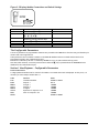
Figure 3.2 Display Module Connections and Switch Settings
POSITION ON
1
FUNCTION
2
Enables all Program Keys
d b c & a
3
Enables e and f Function Keys
Enables g and h Function Keys
Not Applicable
Not Applicable
4
5
6
Enables Keys b and c
FACTORY SETTINGS
ON
ON
ON
ON
OFF
OFF
The Configurable Parameters
A series of parameters or programmable functions are provided in the SMW-HR to allow the user good flexibility for
monitor and control applications.
These parameters are included as constants in the SMW-HR database and are accessed and checked via the
programmer keypad or the communications port.
Data which is entered by the user is retained by EEPROM for up to 10 years without back up power.
New data, when entered, overwrites previous entries when the a key is pressed unless the EEPROM has been
disabled via the communications port.
Section 1 User/Engineer - Configurable Parameters
Password Protection
A 4 digit password number must be entered. The number is accessed when 'PASS' is displayed. At this point, it is
necessary to enter Passport number 001111.
Code
trAn
PASS
SEtPt1
In-Ft1
SEtPt2
In-Ft2
HYSt
LAtCH
8
Function
Transducer Number
Setpoint 1
In-Flight 1
Setpoint 2
In-flight2
Hysteresis for setpoint 1 & 2
Latch for setpoint 1 & 2
Mantracourt Electronics Limited SMW-HR User Manual
Value
000000 to 000012
001111
±999999
±999999
±999999
±999999
±999999
000000 to 000003
ACtion
Bit value
Bit value
Bit value
Bit value
Bit value
Bit value
Bit value
1
2
4
8
16
32
64
Output action
invert SETPT1
invert SETPT2
invert an-op
Disp = Gross
Setpoint = Gross
An-op = Gross
Printer = Gross
ACtion
Bit value
Bit value
Bit value
Bit value
128
256
512
1024
Output action
Disp = Peak
Setpoint = Peak
An-op = Peak
Printer = Peak
Peak can be either Gross or Net value by selecting bit value 8 or not.
Example, peakhold of gross value on display & An-op = 8 + 128 + 512 Peakhold can be reset from 'LR' contact.
OP LO
±999999
Output Low for An-op scaling
OP Hi
Output high for AN-op scaling
±999999
A-tArE
Auto Tare value
±999999
SCStdY
Not applicable, will default to
000000
rESOL
Display resolution of last digit. This function is performed on
the display data only and does not affect the comms or
printer
000000 to 000250
CP
Comms Protocol. Selects printer or 'FAST' format.
‘CP’ = 0 - 127 sets Printer type.
‘CP’ = 128 sets MANTRABUS communications protocol.
See comms and printer section of manual for further details.
000000 to 0001300
SdSt/
Sets Serial Device Station Number if 'CP' = 128. This sets a
unique address code for each SMW-HR See comms section
000000 to 000254
Sets label for the Printer if 'CP' = 0 - 127.
See the printer section
000000 to 000254
LAbEL
Log no
Log Number
A range of numbers 0 to 19,999 is available. Any sequential
number logging activity can be preset as desired, between
these numbers. The number will reset to zero after 19,999.
The log number is not saved on power fail and resets to zero
on power up.
Section 2 Calibrators - Configurable Parameters
Password Protection
A 4 digit password number must be entered. The number is accessed when 'PASS' is displayed. At this point, it is
necessary to enter Passport number 009999.
Mantracourt Electronics Limited SMW-HR User Manual
9
Code
trAn
Value
Transducer Number
Function
000000 to 000012
PASS
Security Password
009999
CALL
Calibration Low value for mV/V display. Must be less than
CALH. See calibration section.
±999999
CALH
Calibration High value for mV/V display. When CALH is set
to zero the SMW-HR will display the raw A/D value of
between 0 & 524287. See calibration section.
±999999
AdCALL
A/D Calibration low value for CALL. Must be lower input
mV than CALH A/D value. See calibration section
0-524287
AdCALH
0-524287
InPUtA
A/D Calibration high value for CALH. See calibration
section
±999999
dISP A
Cal point 1 display value before Lin conversion. See
calibration section
±999999
InPUtb
Cal point 1 required display value after Lin conversion.
See calibration section
±999999
dISP b
Cal point 2 value for Lin conversion. See calibration
section
±999999
Cal point 2 Display value for Lin conversion. See
calibration section
InPUtC
Cal point 3 value for Lin conversion. See calibration
section
dISP C
±999999
±999999
Cal point 3 Display value for Lin conversion. See
calibration section.
InPUtd
±999999
dISP d
Cal point 4 value for Lin conversion. See calibration
section
±999999
dP
Cal point 4 Display value for Lin conversion. See
calibration section.
000000 to 000005
Decimal Point position for currently selected Transducer.
The following shows the position of the decimal point
Code
Position
000000
999999
000001
9.99999
000002
99.9999
000003
999.999
000004
9999.99
000005
99999.9
10
Mantracourt Electronics Limited SMW-HR User Manual
A-tArE
Auto Tare value
±999999
SCStdY
Not applicable, will default to
000000
dISP AU
Number of A/D readings taken before the display is
updated. This in conjunction with ‘FILTER’ sets the display
update rate
000001 to 000255
rESOL
t-SEnS
000000 to 000250
Display resolution of last digit. This function is performed
on the display data only and does not affect the comms or
printer
000000 to 000002
Keypad setting of Gain. Used in conjunction with link LK1
on input module to provide the following gains in mV/V,
1.25, 2.5, 5, 7.5, 15 & 30. Note: ‘t-SEnS’ must be set
before Auto calibration takes place. See calibration
section for more detail
FILtEr
Sets the A/D sample frequency and notch Filter. This is
factory set to 1953 and should not be adjusted. See
calibration section.
000019 to 002000
CP
Comms Protocol. Selects printer or 'FAST' format.
‘CP’ = 0 - 127 sets Printer. ‘CP’ = 128 sets ‘FAST’
communications protocol. See comms and printer section
of manual for further details
000000 to 000130
SdSt/
Sets Serial Device Station Number if 'CP' = 128. This sets a
unique address code for each SMW-HR. See comms section.
000000 to 000254
LAbEL
Sets label for the Printer if 'CP' = 0 - 127. See the printer
section.
000000 to 000254
Log no
Log Number
A range of numbers 0 to 19,999 is available. Any
sequential number logging activity can be preset as
desired, between these numbers. The number will reset to
zero after 19,999. The log number is not saved on power
fail and resets to
zero on power up.
Mantracourt Electronics Limited SMW-HR User Manual
11
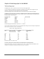
Chapter 4 Strain Gauge Input to the SMW-HR
The Strain Gauge Input
The SMW-HR offers a direct connection to most low level (foil) strain gauge sensors.
A 10 volt excitation is provided and it is monitored to compensate for any variation due to supply drift, Load
regulation or voltage drop in the cable between the sensor and the SMW-HR.
The maximum supply current is 150mA which allows for the connection of upto 6 x 350 R Strain gauges.
The SMW-HR’s A/D provides 19 bits of resolution (1 in 500,000). The Gain of which can be selected by means of a
gain link on the input board (LK1) & by the ‘t-SEnS’ mnemonic. Below is a table showing the relationship between
the Gain link & the ‘t-SEnS’ mnemonic.
MV/V INPUT GAIN
1.25mV/V
2.5mV/V
5mV/V
7.5mV/V
15mV/V
30mV/V
‘t-SEnS’ SETTING
2
1
0
2
1
0
LINK LK1
Fitted
Fitted
Fitted
Not Fitted
Not Fitted
Not Fitted
Default setting is gain link fitted with ‘t-SEnS’ set to 1 i.e. 2.5mV/V
The A/D Sample frequency & Notch filter can be set using the 'FILtEr' setting. The A/D can sample at frequencies of
10Hz to 1KHz. The value set in ‘FILtEr’ is calculated as
FILTER = 19531 / Required sample in Hz
The resolution of the A/D is changed with the value set in 'FILtEr' as outlined in the table below.
-3db Frequency
Resolution
Data o/p rate in Hz
Filter
in Hz
in bits
& first notch of filter
10
1953
25
781
50
390
60
325
100
195
78
250
500
39
1000
19
Min value of 'FILtEr' is 19. (Limit of A/D)
19
17.5
17
16.5
16
12.5
10.5
8
2.62
6.55
13.10
15.72
26.20
65.50
131.00
262.00
This value is Factory Set to 1953 and should not be changed without consulting the factory.
Display update frequency is set by the A/D update rate set in ‘FILtEr’ & 'dISPAU' which sets the number of A/D
readings to be averaged before display and communications ports are updated.
12
Mantracourt Electronics Limited SMW-HR User Manual
Calibration
Switch on the SMW-HR and allow it to stabilise for 30 minutes to obtain the best performance
It is important that the gain, set by ‘t-sens’ & LK1, is correct for the strain gauge sensitivity before proceeding
with the calibration
Apply a test weight of about 5% of required operating range to the strain gauges.
Enter the menu using the password from page 3-5, scroll to ‘CALL’. Enter programming mode and set ‘CALL’ value
to that of the applied weight. For calibration to be successful program mode must be entered even if ‘CALL’ has the
required value already set. Use the scroll key to move onto ‘CALH’.
Apply a test weight of about 80% of required operating range to the Strain gauges.
Enter programming mode and set ‘CALH’ value for the applied weight. Again program mode must be entered even if
‘CALH’ has the required value already set.
For calibration to be successful the ‘CALL’ calibration weight must be less than the ‘CALH’ weight.
Press the a key, the calibration constants will now be stored into EEPROM. the display will revert to the live input
value which should be that of ‘CALH’.
The values for 'ADCALL' and 'ADCALH' are automatically inserted once the auto calibration routine is completed.
These values should NOT be altered. It is advisable however, to record the values for ‘CALL’, ‘CALH’, ‘ADCALL’ &
‘ADCALH’ as should these values be lost through operator error they can be re-entered from the keypad without the
need of repeating the above procedure.
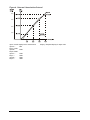
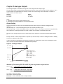
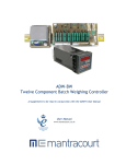
4 Point Linearisation
Any non linearity of the system may be reduced by using a 4 point linearisation routine. The 4 points being entered
under mnemonics ‘InPUt A’ to ‘dISP d’.
System non-linearity can be determined by plotting a graph of weights applied against display value. 3 straight lines
can be applied to this curve, the end of each line providing one of the 4 linearisation points. These are entered as
display value for non-linearised ‘InPUt’ against required ‘dISP’ value.
Notes on 4 point linearisation (See Figure 4-1)
1. All 4 points must be entered
2. A minimum value of 500 digits between each value must be observed.
3. The line is extended above point ‘D’ in a straight line set by point ‘C’ & ‘D’
4. The line is extended below point ‘A’ in a straight line set by point ‘A’ & ‘B’
5. If all 4 points are set to zero then no linearisation is applied.
Mantracourt Electronics Limited SMW-HR User Manual
13
Figure 4.1 Internal Linearisation Protocol
4000
3000
2000
1000
Input = Actual Display before Linearisation
Input A =
990
Disp A = 1000
Input B =
2200
Disp B = 2000
Input C =
3300
Disp C =
3000
Input D =
3900
Disp D =
4000
14
Display = Required display for input value
Mantracourt Electronics Limited SMW-HR User Manual
Chapter 5 Analogue Outputs
Two analogue outputs are available offering a DC current range and a DC voltage range.
They are fully scalable, optically isolated and generated from the value as selected under 'Action' mnemonic. The 4
to 20 mA output is precalibrated to an accuracy of within 0.15% of the range. The 0-10V output is accurate to
within 2% of the 4 to 20mA output.
Ooutput
Range
DC Voltage
0V to 10V
DC Current
4 to 20mA
Notes:
1. Maximum current load on voltage modules is 2mA
2. Maximum drive voltage available in current modules is 20V
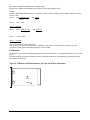
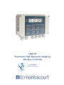
Output Scaling
Output scaling factors are set by the user and determine the display range over which the analogue module
operates.
(OP LO) Output Low - This sets the displayed value at the module's minimum output.
(OP HI) Output High - This sets the displayed value at maximum output. If the display is outside the range defined by
OP LO and OP Hi, the analogue output will remain constant at its minimum or maximum output value.
Inversion of the analogue output can be set by the output action mnemonic OA (See Relay Output Module Chapter
6).
Example: Assume a 4-20mA output module is required to provide an output of 4mA for 1000Kg and 20mA for 6500Kg.
Set OP LO to 1000 and OP Hi to 6500
It will be necessary to determine OP LO and OP Hi by graphical or mathematical means if the known display values
do not coincide with the minimum and/or maximum analogue output.
Figure 5.1 Analogue Output
Max +19999
OP HI=6500
Output scaled over the
complete display range ie
OP HI = +19999
OP LO = -19999
OP LO 1000
Output scaled over the
complete display range ie
OP HI = +6500
OP LO = +1000
Display = 0
Min -19999
Min 4mA
Analogue Output
Max 20mA
Method of Calculating OP LO and OP Hi from any known output values
OP LO = Low
- (Display span) (Low output - Min output)
Display
(High output - Low output)
OP Hi = High
+ (Display Span) (Max output - High output)
Display (High output - Low output)
Low output = Known low output
High output = Known high output
Min output = Lowest measurable value of output module
Mantracourt Electronics Limited SMW-HR User Manual
15
Max output = Highest measurable value of output module
Display span = Highest required display value minus lowest required display value.
Example:
Using a 4.20mA output module where it is required to produce 6mA at a display value of 400 and 18mA at a display
value of 1100.
OP LO = 400 -( (700) (6 - 4) ) =
400-(1400)
(18 -6)
12
OP LO =
400 - 116.66
OP LO =
283.34
OP Hi =
1100 + (700) (20 - 18) = 1100+ (700 x 2)
(18 - 6)
12
OP Hi =
1100 +116.66
OP Hi =
1216.66
Note 1: OP Hi must be greater than OP LO
Note 2: If OP LO or OP Hi are greater than ± 19999 then divide both OP LO and OP Hi by 10, this will give less
resolution. Decimal point can be placed anywhere to suit reading.
Calibration
Re calibration can be made by adjusting the gain and offset potentiometers, or by adjusting the values of OP LO and
OP Hi.
An offset can be achieved by increasing the values of both OP LO and OP Hi, and the gain by increasing the range
between OP LO and OP Hi.
Figure 5.2 Showing the Potentiometers for Gain and Offset Adjustment
GAIN
ADJUST
OFFSET
ADJUST
16
Mantracourt Electronics Limited SMW-HR User Manual
Chapter 6 Relay Output Module
General Description
The Relay output module provides output control signals which can be used for switching functions such as ON/OFF
control and alarm indications. The relays are activated by the values programmed for the Set Points. The output
configuration will be for open or closed relay contacts and latching.
Output
Function
2 Relays
SPCO on SP1 and SP2
The connections for which are shown in Chapter 2
Module Functions
The SMW-HR can be programmed so that the relay output module reacts to all or any of the following functions:
• Set points
• In Flight compensation
• Hysteresis
• Relay inversion
• Latching
Set Points (SP)
Set points are used to produce output signals at any required value so that the operation of the monitored net value
can be maintained to preset levels. Any excursion beyond set points will activate the relay or relays, to provide
alarm or initiate control as required.
Two set points (SP1) and (SP2) can be programmed to suit different applications. The actions of either or both set
points can inverted if required.
For normal operation the set point output is active until the input reaches the set point level. In this condition when
the input value is less than the set point, the SP indicator is on and the output relay is energized producing a closed
circuit on a normally open contact. When the set point value is reached, the SP indicator is off and the relay is deenergized producing an open circuit output.
For an inverted operation the reverse conditions apply.
Normal and inverted action is determined by the direction of the input value as it changes.
For example: In alarm applications.
A High-High operation allows for a rising net value to operate on two set points to define an acceptable quantity,
weight or band of operation.
A Low-Low operation operates on a falling value.
A High-Low operation will operate on a rising or falling value, setting a 'band' by one set point operating normally
and the other being an inverted action.
allowing the In Flight amount to make up the required total set by SP1. A similar situation exists for SP2.
In Flight Compensation
The setting of an In Flight value causes the set points to automatically adjust to control the flow of the material
being weighed.
For example, if SETPT1 is used to control a flow, a certain amount will be 'In Flight' between the supply point and
receiving point causing a positive error when the required weight is reached. The In Flight compensation value is
adjusted by the user to 'reduce' SETPT1 to prematurely stop the flow, allowing the In Flight amount to make up the
required total set by SETPT1. A similar situation exists for SETPT2.
Mantracourt Electronics Limited SMW-HR User Manual
17
Hysteresis (HYS)
Once a Hysteresis value has been set, it will be applied to both set points entered. It is effective for both normal
and inverted action.
When Hysteresis is applied to set points with normal output action, the input is allowed to rise to the set point
value and the output is then turned off. The output is held off until the input value has dropped to the set point
minus the Hysteresis value.
For inverted action the input drops to the set point and the output goes off and comes on again when the input rises
to the set point plus the Hysteresis value.
Output Action (Action)
The Output Action facility allows the user to determine whether set points produce normal or inverted output
operation. The Output Action (ACTION) is entered by a code to suit the requirements of the user.
11 Output Action options are available.
The value of the ACTION to be entered in the algebraic sum of the following components:Bit value 1
invert SETPT1
Bit value 2
invert SETPT2
Bit value 4
invert an-op
Bit value 8
Disp = gross
Bit value 16
Setpoint = gross
An-op = gross
Bit value 32
Printer = gross
Bit value 64
Disp = Peak
Bit value 128
Setpoint = Peak
Bit value 256
An-op = Peak
Bit value 512
Printer = Peak
Bit value 1024
Peak can be either Gross or Net value by selecting bit value 8 or not.
Example, peakhold of gross value on display & An-op = 8 + 128 + 512 Peakhold can be reset from 'LR' contact.
Latching Outputs (LAtCH)
The latching facility allows the relay module output to be held until reset either by keypad, external remote or via
the communications port. Latching is applied to the off status of the relay SETPT1 or SETPT2.
SETPT1
Unlatched
Latched
Unlatched
Latched
SETPT2
Unlatched
Unlatched
Latched
Latched
Code
0
1
2
3
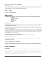
Figure 6.1 LR1 Module
Figure 6.2 Installation of LR1
To meet the Specified EMC Fast transient requirements it is
important that the ferrite ring supplied is fitted as per the
following instructions.
Illustration showing ferrite ring FEC 323-4940 fitted to the LR1 relay
wiring.
Two turns of the wiring are passed through the ring positioned
12cm from the LR1 end of the cable to improve immunity to
electrical fast transients and bursts.
18
Mantracourt Electronics Limited SMW-HR User Manual
Chapter 7 The Communications Port
Introduction
The SWM-HR communications port provides for a 2 way data link. An intelligent host e.g. Personal Computer, Main
Frame or PLC is able to acquire the SWM-HR’s displayed value and read or modify the user configurable parameters,
using any of the following:a) RS232/485 - for a one to one communication (as in the case of a printer, PC or PLC).
b) RS485 - for the connection of up to 25, SWM-HR units on a single RS485 line.
c) 20mA Current Loop - for up to 250, SWM-HR units on a single RS232/485 line, via the IF25 interface. With high
noise immunity and isolation over distances up to 1Km.
3 communication formats, MANTRABUS, ASCII, and PRINTER, are selected from the mnemonic CP via the keypad, of
the programmer.
Integrity is ensured by pre-programmed default parameters should a loss of communications with the host occur.
Serial Communication Protocol
General
Incoming data is continually monitored by the SWM-HR on its serial input line.
Each byte of data is formatted as an eight bit word without parity, preceded by one start bit and followed by one
stop bit.
Transmission and reception of data up to 19.2K Baud is possible, the actual rate being selected by an 6 way link on
the communications module. The Baud rate depends upon the communications, hardware specification, distance
and cable type.
See Comms for Baud Link settings. Chapter 7
MANTRABUS Format - selected when CP is 128
To signify commencement of a new 'block' of data, the HEX number FFH is used as a 'frame' character, followed by
the station number of the unit under interrogation. This is entered via the SWM-HR keypad under mnemonic SDSt
and ranges from 0-254).
The SWM-HR acts upon incoming data only if its own station number immediately follows the FFH character.
New data must be received as a string of four nibbles (bits 7-4 set to zero) which are assembled into two bytes and
written into the variables store within the SWM-HR. The most significant nibble must be received first and the last
nibble must have the most significant bit (bit 7) set to indicate the end of data. This is followed by the checksum.
The data transmitted from the SWM-HR is always sent as complete bytes. The station number precedes the data and
the checksum follows the data. The data format used is signed 15 Bit. The most significant Bit of the most
significant Byte is set for negative numbers.
Operation
There are two modes of operation, namely data requests by the host controller and data changes. Data requests
from the SWM-HR consist of either a complete dump of the data variables stores in RAM or the display reading.
Data changes consist of writing new data to SWM-HR variables, thus changing parameters such as Set Points, in
flights etc.
An acknowledgement message is returned to the SWM-HR to indicate that the new data has been acted upon.
Updating
The required mode or variable to be updated is determined by the station number followed by the command byte.
An EXOR checksum consisting of the station number command byte and any following data must be appended to the
received data. It is most important that the byte proceeding the checksum must have its most significant bit set to
signify the end of data.
The SWM-HR works out its own checksum and, if it disagrees with the received one, a Not Acknowledge (NAK)
message is returned.
Mantracourt Electronics Limited SMW-HR User Manual
19
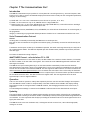
Communications Commands
The following is a list of commands available for reading to or writing from the SWM-HR.
Description
Command No.
Data dump including Gross & Net values
1
Returns Gross & Net values
2
Spare
3
Write to channel number (sets current transducer)
4
Write to SETPT1
5
Write to IN-FT1
6
Write to SETPT2
7
Write to IN-FT2
8
Write to HYST
9
Write to LATCH
10
11
Write to ACTION
12
Write to OP LO
Write to OP Hi
13
14
Write to CALL
15
Write to CALH
Write to ADCALL
16
Write to ADCALH
17
Write to CAL1 I
18
Write to CALI d
19
Write to CAL2 I
20
Write to CAL2 d
21
Write to CAL3 I
22
Write to CAL3 d
23
Write to CAL4 I
24
Write to CAL4 d
25
Write to DP
26
Write to A-TARE
27
Write to SCSTDY
28
Write to DISPAV
29
Write to RESOL
30
Write to TSENS
31
Write to FILTER
32
Write to CP
33
Write to SDST
34
Request AUTOTARE
100
Request RELAY RESET
101
Reset PEAK HOLD
102
Reset TARE VALUE TO ZERO
103
Set display to GROSS
104
Set display to NET
105
Disable EEPROM
106
Enable EEPROM & READ TO IT
107
Enable EEPROM & WRITE TO IT
108
Disable KEYPAD
109
Enable KEYPAD
110
111
Set A/D
Command 1 Request for all data:
DATA TRANSMITTED TO SMW-HR FOR COMMAND 1
0FFH, Station Number, 081H, Chksum
Where Chksum = Station number EXOR with 081H.
Command 1 Request for all data:DATA TRANSMITTED TO SMW-HR FOR COMMAND 1
20
Mantracourt Electronics Limited SMW-HR User Manual
0FFH, Station Number, 081H, Chksum
Where Chksum = Station number EXOR with 081H.
Example: To obtain a complete dump of the variables in the SMW whose Station number is 47 send the following
Data:0FFH, 02FH, 081H, 0AEH
Note MS Bit Set
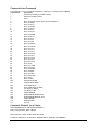
Response to Command 1
Bytes
1
2, 5
6-9
10
11-14
15-18
19-22
23-26
27-30
31-34
35-38
39-42
43-46
47-50
51-54
55-58
59-62
63-66
67-70
71-74
75-78
79-82
83-86
87-90
91-94
95-98
99-102
103-106
107-110
111-114
115-118
119-122
123-126
127-130
131-134
135-138
139-142
143
144
SDST
Gross Value
Net Value
Status Flag
tRAN/CHANNEL
PASS
SETPT1
IN-FT1
SETPT2
IN-FT2
HYST
LATCH
ACTION
OP LO
OP HI
CALL
CALH
ADCALL
ADCALH
INPUTA
DISP A
INPUT B
DISP B
INPUT C
DISP C
INPUT D
DISP D
Dp
A-TARE
SCSTDY
DISPAV
RESOL
TSENS
FILTER
CP
SDST
LOG NUMBER
EEPROM STATUS
EX-OR CHEKSUM
Mantracourt Electronics Limited SMW-HR User Manual
21
COMMAND 2 REQUEST DISPLAY DATA
DATA transmitted to SMW-HR for Command 2.
0FFH, Station number, 082H, Chksum
Where Chksum = Station number EXOR with 082H
Example: To obtain the display reading of an SMW-HR whose station number is 47 send the following Data:
0FFH, 02FH, 082H, 0ADH
Note MS Bit Set
Response to Command 2
Bytes
1
2, 5
6-9
10
11
12
SDST
GROSS VALUE
NET VALUE
STATUS FLAG
DECIMAL POSITION
EX-OR CHECKSUM
STATUS FLAG
Bit
0
1
2
3
4
5
6
7
Flag
RELAY 1 ON
RELAY 2 ON
NOT USED
NOT USED
NOT USED
NOT USED
SCALE STEADY
GROSS/NET DISPLAY SELECTED
COMMANDS 4 TO 34: Write data to SMW-HR Parameter
Commands 4 to 34 all have the same format.
Format for data transmitted to SMW-HR for Commands 4 to 22:0FFH, Station No, Command No, MSN, NIB7, NIB6, NIB5, NIB4, NIB2, LSN, CHKSUM
= Most significant nibble of data
Where MSN
NIB7-2
= Nibble of data between MSN and LSN
LSN
= Least significant nibble of data with MSBIT set
CHKSUM
= The following EXOR’d with each other, Station number,
command number, MSN, NIB7-2, LSN with MSBIT set
Example: To change Dp to 3 on a SMW-HR whose station number is 47. The following data is sent.
0FFH,02FH,00FH,00,00,00,00,00,00,00,83H, 0A3H
Note MSBIT set
Response to COMMAND 4 to 34
If the data has been accepted by the SMW-HR then the following acknowledgement string is transmitted by the
SMW-HR.
Station number, 06H (ACK)
If there are any errors with the data received by the SMW-HR then the following
Not Acknowledgement (NAK) string is transmitted by the SMW-HR:Station number, 015H (NAK)
22
Mantracourt Electronics Limited SMW-HR User Manual
Commands 100 onwards
These commands perform action and require only the command number to be transmitted to the SMW-HR i.e.
To disable the keypad of device 47 using command 105 the following data is sent
0FFH,2FH,E9H,C6H
MS BIT SET
These commands will be acknowledged by an 'ACK' or if an error a 'NAK' proceeded by the station number.
Example of a Basic Code to Communicate with MANTRABUS
open the serial port with no handshaking
OPEN"COM2:4800,N,8,1,RS,DS,BIN" FOR RANDOM AS#1
request display from device 1
Frame FF
Station No
Command 2
1
and add 80 hex
to this byte as it
is the last before
as the checksum
Checksum of
all bytes except frame
talk$=CHR$(&HFF)+CHR$(&H1)+CHR$(&H82)+CHR$(&H1 XOR&H82)
print the string to the port
PRINT#1,talk$;
(must add semicolon after string to stop transmitting a carriage return)
wait for a while (this depends on how many bytes you are expecting and the baud rate!)
input all the bytes in the serial buffer
input.from.smw-hr$=INPUT$(LOC(1),#1)
Mantracourt Electronics Limited SMW-HR User Manual
23
Register Allocation
Register shall be allocated the following values. Odd values are used as a register is only 16 bits & data will be read
as 32 bits. For action commands data is ignored but again 2 registers must be written to. See examples.
GROSS DISPLAY VALUE
40001
NET DISPLAY VALUE
40003
40005
STATUS BYTE. INCLUDES SETPOINT STATUS, EEPROM (More Detail To Follow)
DUMMY for continuity only
CHAN
40007
40009
PASS
SETPT1
40011
40013
IN-FT1
40015
SETPT2
IIN-FT2
40017
40019
HYST
40021
LATCH
ACTION
40023
40025
OP LO
40027
OP HI
ACALL
40029
ACALH
40031
ADCALL
40033
ADCALH
40035
DTP1I
40037
DTP1D
40039
DTP2I
40041
DTP2D
40043
DTP3I
40045
DTP3D
40047
DTP4I
40049
DTP4D
40051
DPSEL
40053
DISZER
40055
SCALES
40057
AVRGE
40059
RESOL
40061
GAIN
40063
40065
FILTER
40067
CP
40069
SDST
40071
LOGNUM LOG NUMBER printer only
40073
Action commands
40101
40103
40105
40107
40109
40111
40113
40115
40117
40119
40121
40123
DO AUTOTARE
DO LATCH RELAY RESET
DO PEAK HOLD RESET
RESET TARE VALUE TO ZERO
SET DISPLAY TO GROSS
SET DISPLAY TO NET
DISABLE EEPROM
ENABLE EEPROM & READ DATA FROM IT INTO RAM
ENABLE EEPROM & WRITE DATA IN RAM TO IT
DISABLE KEYPAD
ENABLE KEYPAD
RECONFIGURE A/D AFTER WRITE TO GAIN OR FILTER
Examples
24
Mantracourt Electronics Limited SMW-HR User Manual
The following are examples of the commands. Channel 1 has been used for examples
Read NET value from Channel 1
Data sent from PLC
01 03 9C 43 00 02 1B 8F
Data sent from SMW-HR
01 03 9C 43 00 02 ,MSB, NMSB, NLSB, LSB, CRC-16 HI, CRC-16 LO
Auto-Tare Channel 1
Data sent from PLC
01 10 9C A5 00 02 04, xx, xx, xx, xx, CRC-16 HI, CRC-16 LO
Where xx = Don’t care
Data sent from SMW-HR
01 10 9C A5 00 02 CRC-16 HI, CRC-16 LO
Set Setpoint 1 on Channel 1
Data sent from PLC
01 10 9C 4D 00 02 D1, D2, D3, D4, CRC-16 HI, CRC-16 LO
Where D1 = data MSB, D2 = data NMSB, D3 = data NLSB, D4 = data LSB
Data sent from SMW-HR
01 10 9C 4D 00 02 CRC-16 HI, CRC-16 LO
A note about EEPROM
All user set parameters are stored in EEPROM where they are recalled on power up. The EEPROM has a limited
number of write cycles of between 10,000 & 1,000,000. If setpoint data is to be written to the SMW-HR we suggest
disabling the EEPROM from the comms using register 40113. This register is written to with no data as the Auto-tare
command.
Disable EEPROM on Channel 1
Data sent from PLC
01 10 9C B1 00 02 04, xx, xx, xx, xx, CRC-16 HI, CRC-16 LO
Where xx = Don’t care
Data sent from SMW-HR
01 10 9C B1 00 02 CRC-16 HI, CRC-16 LO
Mantracourt Electronics Limited SMW-HR User Manual
25
ASCII Protocol
Host Transmission
The command structure is based on the following format
Framing
Address
Separator
Command
Character
!
001
:
CALH
Response
Data
=
-99.9999
End of
frame
<CR>
For example !001:SP1=123.456<CR>
An explanation of each field is as follows.
Framing character: A single “!” is used to “frame up” the receiving devices allowing all instruments to see the start
of a new message. The “!” character will only be transmitted by the host for framing purposes
Address: The Address is always 3 ASCII characters representing the devices to which the command is intended.
Address 999 is reserved for Broadcast addressing for which there is no response.
Separator: Must always be sent by host. As no Checksum or message verification technique is used this separator
character is a further check by the instrument on the incoming message.
Command: Up to 6 alpha-numeric characters can be used in this field. The mnemonic approach has been used as
this would be intended to be as the mnemonics will appear to the user from the 7 segment display thus saving the
user remembering a command list. Upper and lower case can be used within field as no discrimination is made.
Response: Defines what sort of response is expected. If a “=” appears here then data is expected to follow. If a “?”
is received then the host is expecting data back from the instrument. If nothing is received then the command is
expected to be an action type i.e. Tare, relay reset. In all cases the instrument will respond with data (see
Instrument response) except when the address is 999 which is a general broadcast address.
Data: This field can include any printable ASCII characters accept “!”. A maximum string length of 40 characters will
apply to this field. The field will be decoded by a command specific routine in the instrument. This open approach
allows good flexibility for the data into the instrument which could include modem strings Pass words etc. etc.
End of frame: A <CR> must always transmitted to indicate end of frame & it will be from this point that the data
will be decoded from the instruments receive buffer & acted upon
There are 3 basic command types, command read which are used to read data from an instrument, command write
which writes data into the instruments & action commands which perform an instrument function such as tare or
EEPROM disable. The following are examples of the 3 types.
Command Read
Framing
Address
Character
!
001
Command Write
Framing
Address
Character
!
001
Command Action
Framing
Address
Character
!
001
Separator
Command
d
disp
Response
:
Command
d
RESOL
Separator
Command
:
RESREL
:
Separator
Data
End of
frame
<CR>
Response
Data
=
0.10
End of
frame
<CR>
Response
Data
?
End of
frame
<CR>
Response from Instruments
A response from the instrument is always sent, the only exception being when a “broadcast” command is issued.
Broadcast commands will only be accepted for Action & write commands. The responses are as follows :Command read.
26
Mantracourt Electronics Limited SMW-HR User Manual
Returns the requested value specified by the command. The length of the alpha-numeric data is not fixed (max.
length will be 40 characters. Returned data will be terminated with a <CR>. Examples of returned data are as
follows.
2.34<CR>
-56.78<CR>
1999.99<CR>
GEORGE<CR>
If the Command is not understood by the instrument then a “?” is transmitted followed by a <CR> is sent by the
instrument.
Command write.
If the command & value is accepted by the instrument then a <CR> is transmitted, if not accepted a “?” followed by
a <CR> is sent.
Command action.
If the command is accepted by the instrument then a <CR> is transmitted, if not accepted a “?” followed by a <CR>
is sent.
Response timing.
From receipt of the host’s terminating <CR> to a response from the instrument is expected to be within 50mS.
Continuous output stream
By sending an “XON” the instrument will transmit it’s display value every display update until an “XOFF” or framing
character is received. The display value can be selected under the “Action” mnemonic. This MUST only be used in a
1 to 1 system.
Mantracourt Electronics Limited SMW-HR User Manual
27
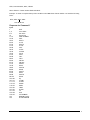
List of commands
GROSS
NET
STATUS
TRAN
PASS
SETPT1
IN-FT1
SETPT2
IN-FT2
HYST
LATCH
ACTION
OPLOW
OP HIGH
CALL
CALH
ADCALL
ADCALH
INPUTA
DISP A
INPUTB
DISP B
INPUTC
DISP C
INPUTD
DISP D
DP
A-TARE
SCSTDY
DISPAV
RESOL
T-SENS
FILTER
CP
SDST
LOGNUM
Current gross value. Read only
Current net value. Read only
Current Status flag. read only
Transducer selected . Power on default = 0
Read only
Setpoint 1
In-flight 1
Setpoint 2
In-flight 2
Hysteresis for setpoint 1 & 2
Latch for setpoint 1 & 2
Output action
Output Low for An-op scaling
Output high for An-op scaling
Calibration low point
Calibration high point
A/D value for low calibration point
A/D value for high calibration point
4 point linearisation input value A
4 point linearisation display value A
4 point linearisation input value B
4 point linearisation display value B
4 point linearisation input value C
4 point linearisation display value C
4 point linearisation input value D
4 point linearisation display value D
decimal point position
Auto-Tare value
Scale steady value which must be held for 2 seconds Unit will not Auto tare
til scale steady. Can be disabled with value of 0
Display averaging
Display resolution
A/D gain
A/D filtering
Comms protocol. Read only
Serial device station number or Label for printer. Read only
Incremental log number for printer. reset to 0 on power up
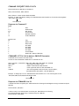
Action commands
DOTARE
RESREL
RESPH
RESTAR
SETGRS
SETNET
DISE2R
ENE2RR
ENE2RW
DISKEY
ENKEY
SETAD
HELLO
28
Perform Auto-Tare
Reset Latch relays
Reset Peak hold
Reset Tare value to zero
Set display to Gross value
Set display to Net value
Disable E2rom
Enable E2rom & read from it
Enable E2rom & write RAM to it
Disable Keys
Enable keys
Reset A/D using filter & t-sens values
Used to determine if device present. Returns CR
Mantracourt Electronics Limited SMW-HR User Manual
SMW-HR Printer Interface
(CP must be set between 0 - 127) Dependant on printer type
Printer selection enables the SMW-HR to print its current display value to a printer via its communications port. This
display value can either be assigned a date and time stamp. A label can be suffixed to the printed display value
using the mnemonic 'LAbel'. A large range of labels are available to the user. (See table below.)
'LAbel' Value
Label
'LAbel' Value
Label
psig
1
mV/V
17
psia
2
kN
18
Pa
3
N
19
kPa
4
MN
20
MPa
5
kgf
21
6
gf
22
kp
7
daN
23
kpm
8
lbf
24
kgfm
9
tonf
25
Nm
10
UStonf
26
kNm
ozf
27
MNm
11
12
g
28
lbf ft
13
t
29
lbf in
kg
30
oz in
14
bar
31
mm
15
mbar
16
The time and date are set in the TDP printer itself using its own menu. The printer allows the entry of an additional
custom text message.
Three connections are required between the SMW-HR communications port and the printer with a maximum cable
length of 100 metres.
Additional Mnemonics for the Printer Operation:
CP
At this mnemonic the printer type and print format number is selected. This number
being
appropriate to the type of printer used. Details are advised with each type of printer
selected.
Present types available are:- For the ITT IPP-144-40E printer the following numbers apply
0
Prints a sequential log number with the current display and unit of measure
e.g.
00014 0011.3 tonne
1
Prints date and time with a sequential log number, current display and unit of
measure
e.g.
00015 0001.7 tonne
22.05.07 05:06
2
Prints a sequential log number, current display, unit of measure with customer text
message No 1
e.g.
MANTRACOURT ELECTRONICS SMW-HR PRINTER
00012 000.2 tonne
3
Prints date and time with a sequential log number, current display, unit of measure
and a customer text message No.1
e.g.
MANTRACOURT ELECTRONICS SMW-HR PRINTER
00013 0023.6 tonne
22.05.07 12:03:04
Mantracourt Electronics Limited SMW-HR User Manual
29
4-7
8,9
10
12
Digitec 6700 series. As ITT Printer 0-4
Amplicon AP24 and AP40 (9 inverts Text)
Eltron LP2142 - (The label file must be called 'MEL' and the label must contain a LOG
NUMBER, THE DISPLAY VARIABLE & a LABEL (not zero).
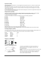
ASCII string on print command
Provision is made in the SMW for communications via one of two module options:
LC1
The 20mA current loop module, for connection to an IF25 interface.
LC3
An RS232/485 isolated module, for connection to a PC or PLC, in a single or multiple
function
Connections for these options are shown:-
Figure 7.1 LC1 Current Loop
Figure 7.2 IF25 Connecting Multiple SMW-HRs
Connecting Multiple SMW-HR to the IF25 Interface
Notes
1. Maximum loop voltage is 50V dc.
2. Loop is isolated from host and SMW-HR. Loop should be earthed via Rx - on IF25/254
3. IF25 used for up to 25 SMW.
4. At 19,200 Baud, max.cable length is 100m metres, using cable type BICC H8085.
30
Mantracourt Electronics Limited SMW-HR User Manual
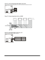
Figure 7.3 LC3 Isolated RS232/485~Mode Connections
Note: LK2 when multi dropping RS485, the last device should be terminated with 120R
LC3
LK2
Signal
LK1
Tx+
Rx+
RxTx+
Tx-
19200
9600
4800
2400
1200
TxRx+
RxSCR
Figure 7.4 Connecting Multiple Units on RS485
COM1/1
+ Tx Tx
+
Rx
Rx
COM1/2
+ Tx Tx
+
Rx
COM1/3
Rx
+ Tx Tx
+
Rx
Rx
COM1/X
+ Tx Tx
+
Rx
Rx
Fit LK2 in
last device
RS232
Figure 7.5 LC3 RS232 Mode Connection to PC
Note: LK1 must be made for RS232 operation
LC3
LK2
19200
9600
4800
2400
1200
LK1
Signal
Tx+
TxRx+
RxSCR
9 Way ‘D’ Skt
25 Way ‘D’ Skt
GND
5
7
Rx
2
3
Tx
3
2
Mantracourt Electronics Limited SMW-HR User Manual
31
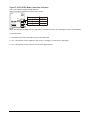
Figure 7.6 LC3 RS232 Mode Connection to Printer
Note 1: LK1 must be made for RS232 operation
Note 2: If no RTS is available from the printer, fit LK2
LC3
LK2
Signal
LK1
Tx+
19200
9600
4800
2400
1200
Tx-
GND
ITT-Ipp-144
-40E
1&5
Amplicon
AP24/AAP40
15
Rx
2
3
RTS
8
P
Rx+
RxSCR
NOTE :
When using an RS232 to RS485 converter which has a non-biased receiver, the following actions are recommended:To bias the device:
1. Terminate the receiver with 140R in place of the usual 120R
2. Fit a 1.5K from the receive negative to the receiver +5V supply, or a 3K3 to the +12V supply.
3. Fit a 1.5K from the receive positive to the receiver supply Ground.
32
Mantracourt Electronics Limited SMW-HR User Manual
Chapter 8 Trouble Shooting Guide
This chapter is designed to assist in the identification of problems relating to the installation and setting up of the
SMW-HR.
1. General Connection and setup parameters. No display on power up.
a) Check supply is present at the SMW-HR terminals.
b) If supply is correct contact Mantracourt.
Display shows (-1 or 1) continually, without a weight applied to the strain gauge.
a) Check input connections to the SMW-HR from the strain gauge.
b) If connecting a 4 wire device ensure terminals 1&2 and 5&6 are linked.
c) Check strain gauge output between input terminals 3&4 of the SMW.
d) Check that the CALH weight is applied and is not the same or lower than CALL.
Display over ranges (-1 or 1) when, or before, the maximum required weight is applied to the strain gauge.
a) Check output of strain gauge is set to the correct sensitivity settings on the DIL switches
Display very noisy
a) If using a 4 wire device ensure terminals 1&2 & 5&6 are linked.
b) Check output voltage of strain gauge.
Display operating in wrong direction
a) Check connections to input terminals 3&4 are correct way round.
b) Check the type of strain gauge - compression or tension.
Unit will not auto calibrate
a) Check that CALH is not zero and its weight is greater than CALL.
b) Check that input is not overranged on CALH weight.
Unit will not Auto Tare
a) Check DP r code for correct setting.
b) Check auto tare sequence, when selected from keypad, is completed within 1 second.
Access to parameters not possible beyond the PASSWORD (PASS)
a) Check for special password if not (1111) with your company or supplier. (Quote serial number as a reference.)
2.
a)
b)
c)
Relay Output Module - Incorrect Relay Operation
Check set point, in flight and hysteresis values are correct.
Check latching and invertion settings in output action (OA) are correct.
Check connections to output terminals.
Remote function (Auto Tare, Peak Hold / Latched , printer fails to operate)
a) Check 'DP-r' for correct value to ensure desired function selected.
3. MANTRABUS / ASCII Format. No Communications
a) Check that a comms module is fitted.
b) Check correct CP code is entered for required protocol.
c) Check connections to SMW from IF25 are correct.
d) Check IF25 green LEDs are on and RX LED is on and TX LED is off.
Press TX TEST , TX LED should light.
e) Check RS232 connections from the host to the IF25 are correct.
f) Check SdSt, serial device station number is correct.
g) Check Baud rate settings on SMW's are correct for the host.
h) Check host comms port is set to 8 bit word, 1 start bit, 1 stop bit, no parity.
i) Check correct protocol is being observed by the host.
j) Check if using ASCII a null character is being sent by most for each Byte expected back.
Mantracourt Electronics Limited SMW-HR User Manual
33
Chapter 9 SMW-HR Specifications
Strain Gauge Input
Calibration
Automatic digital by use of keypad and 1 (or 2) known weights
giving ±0.0015% linearity
Initial Calibration
Linear mV/V input, using auto-cal giving ±0.0015% linearity
SI Units/Linearisation
4 point linearisation and conversion of mV/V value into
engineering units. Optional facility to download mV/V value to a
Computer for conversion using a third order polynomial equation.
Auto Tare
Auto Tare values can also be viewed and manually changed if
required. Auto tare value is retained on power down. Auto Tare is
affected from the field terminals.
Input Sensitivity Range
1.25mV/V to 30m V/V (selectable ranges ±1.25, 2.5, 5, 7.5, 15,
30mV/V)
Zero Temperature
Coefficient
<0.0005% FSO/°C typical with 2.5 mV/V sensitivity selected
Span Temperature
Coefficient
<0.0017% reading /°C (<0.0007% reading /° C Typical)
Excitation
9.6V DC nominal, 160mA maximum
Compensation
By ± sense wires to compensate for cable, connection
Repeatability
<±0.002% reading over 90 days
Display Update Rate
Programmer keypad selectable between 0.1 and 25.5 seconds
Display Average
Set by programmer keypad, up to 64 standard updates
Display Resolution
1:500,000
DC Analogue Outputs
Range MIN
+4
0
Isolation:
MAX
Max Drive
Capability
+20mA
20V (1K)
+10V
2mA
±130V RMS or DC to any other port
Typical Accuracy
% of reading
% of FSD
± 0.08%
±0.08%
± 0.08%
±0.08%
Control / Alarm Relay Output (RR1)
2 SPCO relays, SETPT1 and SETPT2
Contact Rating 50V @ 500mA AC
Setpoint, In Flight Compensation, Hysteresis, Latching and Relay Inversion are set digitally using programmer keypad
and display, in engineering units.
Hysteresis value applies to both SETPT1 and SETPT2. (Fail safe operation by setting inversion to give normally
energised operation).
Latching Reset By volt free contact to field terminals or by communication
34
Mantracourt Electronics Limited SMW-HR User Manual
The Communications Port Data
Operation
All SMW-HR display data can be retrieved via communications port along with relay and EEPROM status.
All SMW-HR user configurable data can be changed including EEPROM enable/display and relay reset. (SMW-HR
Station Number cannot be changed).
The SMW-HR communications port provides for a 2 way data link. An intelligent host e.g. Personal Computer, Main
Frame or PLC is able to acquire the SMW-HR’s displayed value and read or modify the user configurable parameters,
using any of the following:a) RS232/485 - for a one to one communication (as in the case of a printer, PC or PLC).
b) RS485 - for the connection of up to 25, SMW-HR units on a single RS485 line.
c) 20mA Current Loop - for up to 250, SMW-HR units on a single RS232/485 line, via the IF25 interface. With high
noise immunity and isolation over distances up to 1Km.
Protocols available are ASCII and MANTRABUS selectable by the CP mnemonic on the display of the SMW-HR
programmer.
Data Retention and Protection
Retention:
10 years for set values, minimum of 10,000 write cycles, but
typically 1,000,000.
Protection of data and
function(s):
Watchdog timer giving repeat auto resets. Impending power fail
detection and shutdown. Low power detection and hold off.
Environmental
Storage temperature
Operating temperature
Relative humidity
Case sealing
-20 to +70ºC
-10 to +50ºC
95% max non condensing
To IP65
CE Approvals
European EMC Directive
Low Voltage Directive
Physical
Case dimensions
Case materials
Weight
Terminals
Accessibility
2004/108/EC
BS EN 61326-1:2006
BS EN 61326-2-3:2006
2006/95/EC
BS EN 61010-1:2001
Rated for Basic Insulation
Normal Condition
Pollution Degree 2
Permanently Connected
Insulation Category lll
200 x 120 x 75mm
Light grey ABS
725g
2.5mm, saddle field terminals
All electronics accessible through front panel.
Power Supplies
210 - 260v AC, 50 - 60Hz, 10W
97 - 120v AC, 50 - 60Hz, 10W
9 - 32v DC,
50 - 60Hz, 10W
Mantracourt Electronics Limited SMW-HR User Manual
35
SMW-HR Order Codes
Input
Standard strain
gauge
Outputs
Standard Analogue
10v DC / 160mA
Output
DC voltage
DC current
Range
0v to 10v
4 to 20mA
SMW-HR
Optional Modules
Communications Port
Current Loop
Multi Drop
RS232/485
(LC1)
(LC3)
Output
Control/Alarm
Relay
Output
2 Relays
Function
SPCO on SP1
and 2
(LR1)
Power Supplies
220 - 240v AC 50 - 60Hz 10W
110 - 120v AC 50 -60Hz 10W
(LS1)
9 -32v DC 50 - 60Hz 10W
(LS3)
Programming unit Remote Hand Held
Example:
(LP3)
UAB-EX, UAHRLC for mounting choice- please refer to the price list options
(SMW-HR - LR1 - LC3 - LS1)
Standard SMW-HR with relay module and RS232/485 Communications and 110/240 volts AC power supply
SMW-HR Accessories
The following accessories are available to allow for expansion of systems:
Function
Order code
IF25 Interface
Connect up to 25 SMW-HRs
NOTE: Details of the unit appears
in a separate publication.
IF25
Printers
Time / date and display data
Display data only
TDP
DP
36
Mantracourt Electronics Limited SMW-HR User Manual
Instrument Setup Record Sheet
Product
Product Code
Serial No
Tag No
Date
Location
Measurement type, range & engineering units
Communication / Baud Rate
SMW-HR
Password No 001111
trAn
PASS
SEtPt1
In-Ft1
SEtPt2
In-Ft2
HYSt
LAtCH
ACtion
OP LO
OP Hi
A-tArE
SCStdY
rESOL
CP
SdSt or LAb
Log no (for printer
VALUE
Password No 009999
trAn
PASS
CALL
CALH
AdCALL
AdCALH
InPUtA
dISP A
InPUtb
dISP b
InPUtC
dISPC
InPUtd
dISP d
dP
A-tArE
SCStdY
dISP AU
SCStdY
dISP AU
rESOL
t-SEnS
FILtEr
Mantracourt Electronics Limited SMW-HR User Manual
37
CP
SdSt/LabEL
Log no (for Printer)
WARRANTY
All SMW-HR products from Mantracourt Electronics Ltd., ('Mantracourt') are warranted against defective material and workmanship for a period
of (3) three years from the date of dispatch.
If the 'Mantracourt' product you purchase appears to have a defect in material or workmanship or fails during normal use within the period,
please contact your Distributor, who will assist you in resolving the problem. If it is necessary to return the product to 'Mantracourt' please
include a note stating name, company, address, phone number and a detailed description of the problem. Also, please indicate if it is a
warranty repair.
The sender is responsible for shipping charges, freight insurance and proper packaging to prevent breakage in transit.
'Mantracourt' warranty does not apply to defects resulting from action of the buyer such as mishandling, improper interfacing, operation outside
of design limits, improper repair or unauthorised modification.
No other warranties are expressed or implied. 'Mantracourt' specifically disclaims any implied warranties of merchantability or fitness for a
specific purpose. The remedies outlined above are the buyer’s only remedies. 'Mantracourt' will not be liable for direct, indirect, special,
incidental or consequential damages whether based on the contract, tort or other legal theory.
Any corrective maintenance required after the warranty period should be performed by 'Mantracourt' approved personnel only.
ISO 9001
REGISTERED FIRM
CIn the interests of continued product development, Mantracourt Electronics Limited reserves the right to alter product specifications
without prior notice.
Code No. 517-062
38
Mantracourt Electronics Limited SMW-HR User Manual
Issue 2.3
16.04.13