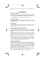
1
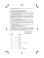
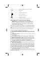
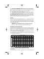
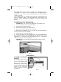
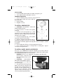
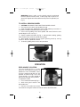
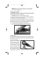
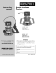
283800 - 07-31-00.QXD
9/23/02
1:34 PM
Page 1
ESPAÑOL: PÁGINA 13
FRANÇAISE : PAGE 25
Instruction
manual
Double Insulated
7"/ 9" Disc Sander
MODEL 7414
To learn more about Porter-Cable
visit our website at:
http://www.porter-cable.com
IMPORTANT
Please make certain that the person who is
to use this equipment carefully reads and
understands these instructions before
starting operations.
The Model and Serial No. plate is located on the main
housing of the tool. Record these numbers in the
spaces below and retain for future reference.
Model No. ______________________________________
Type ___________________________________________
Serial No. _______________________________________
Copyright © 2000 Porter-Cable Corporation
Part No. 283800-007
283800 - 07-31-00.QXD
9/23/02
1:34 PM
Page 2
GENERAL SAFETY RULES
WARNING! READ AND UNDERSTAND ALL INSTRUCTIONS. Failure to
follow all instructions listed below, may result in electric shock, fire and/or
serious personal injury.
WARNING: SOME DUST CREATED BY POWER SANDING, SAWING,
GRINDING, DRILLING, AND OTHER CONSTRUCTION ACTIVITIES
contains chemicals known to cause cancer, birth defects or other
reproductive harm. Some examples of these chemicals are:
• lead from lead-based paints,
• crystalline silica from bricks and cement and other masonry products,
and
• arsenic and chromium from chemically-treated lumber.
Your risk from these exposures varies, depending on how often you do this
type of work. To reduce your exposure to these chemicals: work in a well
ventilated area, and work with approved safety equipment, such as those
dust masks that are specially designed to filter out microscopic particles.
SAVE THESE INSTRUCTIONS
WORK AREA
1. Keep your work area clean and well lit. Cluttered benches and dark
areas invite accidents.
2. Do not operate power tools in explosive atmospheres, such as in
the presence of flammable liquids, gases, or dust. Power tools create
sparks which may ignite the dust or fumes.
3. Keep bystanders, children, and visitors away while operating a
power tool. Distractions can cause you to lose control.
ELECTRICAL SAFETY
1. Double insulated tools are equipped with a polarized plug (one blade
is wider than the other). This plug will fit in a polarized outlet only one
way. If the plug does not fit fully in the outlet, reverse the plug. If it still
does not fit, contact a qualified electrician to install a polarized outlet. Do
not change the plug in any way. Double Insulated
eliminates the need for
the three wire grounded power cord and grounded power supply system.
2. Avoid body contact with grounded surfaces such as pipes,
radiators, ranges and refrigerators. There is an increased risk of electric
shock if your body is grounded.
3. Don’t expose power tools to rain or wet conditions. Water entering a
power tool will increase the risk of electric shock.
4. Do not abuse the cord. Never use the cord to carry the tools or pull
the plug from an outlet. Keep cord away from heat, oil, sharp edges or
moving parts. Replace damaged cords immediately. Damaged cords
increase the risk of electric shock.
5. When operating a power tool outside, use an outdoor extension
cord marked “W-A” or “W”. These cords are rated for outdoor use and
reduce the risk of electric shock.
PERSONAL SAFETY
1. Stay alert, watch what you are doing, and use common sense when
operating a power tool. Do not use tool while tired or under the
influence of drugs, alcohol, or medication. A moment of inattention while
2
283800 - 07-31-00.QXD
9/23/02
1:34 PM
Page 3
operating power tools may result in serious personal injury.
2. Dress properly. Do not wear loose clothing or jewelry. Contain long
hair. Keep your hair, clothing, and gloves away from moving parts.
Loose clothes, jewelry, or long hair can be caught in moving parts.
3. Avoid accidental starting. Be sure switch is OFF before plugging in.
Carrying tools with your finger on the switch or plugging in tools that have
the switch ON invites accidents.
4. Remove adjusting keys or wrenches before turning the tool ON. A
wrench or a key that is left attached to a rotating part of the tool may result in
personal injury.
5. Do not overreach. Keep proper footing and balance at all times.
Proper footing and balance enable better control of the tool in unexpected
situations.
6. Use safety equipment. Always wear eye protection. Dust mask, nonskid safety shoes, hard hat, or hearing protection must be used for
appropriate conditions.
TOOLS USE AND CARE
1. Use clamps or other practical way to secure and support the
workpiece to a stable platform. Holding the work by hand or against your
body is unstable and may lead to loss of control.
2. Do not force tool. Use the correct tool for your application. The
correct tool will do the job better and safer at the rate for which it is
designed.
3. Do not use tool if switch does not turn it ON or OFF. A tool that
cannot be controlled with the switch is dangerous and must be repaired.
4. Disconnect the plug from the power source before making any
adjustments, changing accessories, or storing the tool. Such preventive
safety measures reduce the risk of starting the tool accidentally.
5. Store idle tools out of reach of children and other untrained
persons. Tools are dangerous in the hands of untrained users.
6. Maintain tools with care. Keep cutting tools sharp and clean.
Properly maintained tools, with sharp cutting edges are less likely to bind
and are easier to control.
7. Check for misalignment or binding of moving parts, breakage of
parts, and any other condition that may affect the tool’s operation. If
damaged, have the tool serviced before using. Many accidents are
caused by poorly maintained tools.
8. Use only accessories that are recommended by the manufacturer
for your model. Accessories that may be suitable for one tool may become
hazardous when used on another tool.
SERVICE
1. Tool service must be performed only by qualified repair personnel.
Service or maintenance performed by unqualified personnel may result in a
risk of injury.
2. When servicing a tool, use only identical replacement parts. Follow
instructions in the Maintenance Section of this manual. Use of
3
283800 - 07-31-00.QXD
9/23/02
1:34 PM
Page 4
unauthorized parts or failure to follow Maintenance Instructions may create a
risk of electric shock or injury.
SPECIFIC SAFETY RULES AND SYMBOLS
1. Always use proper guard with grinding wheel. A guard protects
operator from broken wheel fragments.
2. Accessories must be rated for at least the speed recommended on
the tool warning label. Wheels and other accessories running over rated
speed can fly apart and cause injury.
3. Hold tool by insulated gripping surfaces when performing an
operation where the cutting tool may contact hidden wiring or its own
cord. Contact with a “live” wire will also make exposed metal parts of the
tool “live” and shock the operator.
4. Always use an approved guard with those accessories that require a
guard (see ACCESSORIES Section of this manual).
5. Use proper safety equipment. Wear safety goggles to protect your
eyes and wear a protective mask to minimize breathing in the fine dust
created while sanding. NOTE: Some wood contains preservatives which can
be toxic. Take extra care to prevent inhalation and skin contact when
working with these materials.
6. Sanding of lead-based paint is not recommended. Lead-based paint
should only be removed by a professional.
7. Do not install woodcarving blade on this grinder.
8. WARNING: There are certain applications for which this tool was
designed. Porter-Cable strongly recommends that this tool NOT be modified
and/or used for any application other than for which it was designed. If you
have any questions relative to its application DO NOT use the tool until you
have written Porter-Cable and we have advised you.
Technical Service Manager
Porter-Cable Corporation
4825 Highway 45 North
Jackson, TN 38305
SYMBOL
V
A
Hz
W
kW
µF
l
kg
N/cm2
Pa
h
min
s
DEFINITION
..........................
..........................
..........................
..........................
..........................
..........................
..........................
..........................
..........................
..........................
..........................
..........................
..........................
volts
amperes
hertz
watts
kilowatts
microfarads
liters
kilograms
newtons per square centimeter
pascals
hours
minutes
seconds
.......................... alternating current
3
.......................... three-phase alternating current
4
283800 - 07-31-00.QXD
3N
9/23/02
1:34 PM
Page 5
.......................... three-phase alternating current with neutral
n0
.......................... direct current
.......................... no load
.......................... alternating or direct current
.......................... Class II Construction
.......................... splash-proof construction
.......................... watertight construction
…/min .......................... revolutions or reciprocation per minute
ADDITIONAL SAFETY RULES FOR PAINT REMOVAL
WARNING: Extreme care should be taken when removing paint. The
peelings, residue, and vapors of paint may contain lead, which is
poisonous. Exposure to even low levels of lead can cause
irreversible brain and nervous system damage; young and unborn
children are particularly vulnerable.
Before beginning any paint removal process you should determine whether
the paint you are removing contains lead. This can be done by your local
health department or by a professional who uses a paint analyzer to check for
lead.
LEAD-BASED PAINT SHOULD ONLY BE REMOVED BY A PROFESSIONAL.
Persons removing paint should follow these guidelines:
1. KEEP THE WORK AREA WELL VENTILATED. Open the windows and
put an exhaust fan in one of them. Be sure the fan is moving air from inside
to outside.
2. REMOVE OR COVER any carpets, rugs, furniture, clothing, cooking
utensils and air ducts.
3. PLACE DROP CLOTHS in the work area to catch any paint chips or
peelings. Wear protective clothing such as extra work shirts, overalls and hats.
4. WORK IN ONE ROOM AT A TIME. Furnishings should be removed or
placed in the center of the room and covered. Work areas should be sealed
off from the rest of the dwelling by sealing doorways with drop cloths.
5. CHILDREN, PREGNANT OR POTENTIALLY PREGNANT women and
nursing mothers should not be present in the work area until the work is
done and all cleanup is complete.
6. WEAR A DUST RESPIRATOR or a dual filter (dust and fume) respirator
mask which has been approved by the Occupational Safety and Health
Administration (OSHA), the National Institute of Safety and Health (NIOSH),
or the United States Bureau of Mines. These masks and replaceable filters
are readily available at major hardware stores. Be sure the mask fits. Beards
and facial hair may keep the masks from sealing properly. Change filters
often. DISPOSABLE PAPER MASKS ARE NOT ADEQUATE.
7. KEEP FOOD AND DRINK out of the work area. Wash hands, arms, and
face and rinse mouth before eating or drinking. Do not smoke or chew gum
or tobacco in the work area.
5
283800 - 07-31-00.QXD
9/23/02
1:34 PM
Page 6
8. CLEAN UP ALL REMOVED PAINT and dust by wet mopping the floors.
Use a wet cloth to clean all walls, sills and any other surfaces where paint or
dust is clinging. DO NOT SWEEP, DRY DUST OR VACUUM. Use a high
phosphate detergent or trisodium (TSP) to wash and mop areas.
9. AT THE END OF EACH WORK SESSION put the paint chips and debris
in a double plastic bag, close it with tape or twist ties and dispose of properly.
10. REMOVE PROTECTIVE CLOTHING and work shoes in the work area to
avoid carrying dust into the rest of the dwelling. Wash work clothes
separately. Wipe shoes off with a wet rag that is then washed with the work
clothes. Wash hair and body thoroughly with soap and water.
MOTOR
Many Porter-Cable tools will operate on either D.C., or single phase 25 to 60
cycle A.C. current and voltage within plus or minus 5 percent of that shown
on the specification plate on the tool. Several models, however, are designed
for A.C. current only. Refer to the specification plate on your tool for proper
voltage and current rating.
CAUTION: Do not operate your tool on a current on which the
voltage is not within correct limits. Do not operate tools rated A.C.
only on D.C. current. To do so may seriously damage the tool.
EXTENSION CORD SELECTION
If an extension cord is used, make sure the conductor size is large enough to
prevent excessive voltage drop which will cause loss of power and possible
motor damage. A table of recommended extension cord sizes will be found
in this section. This table is based on limiting line voltage drop to 5 volts (10
volts for 230 volts) at 150% of rated amperes.
If an extension cord is to be used outdoors it must be marked with the suffix
W-A following the cord type designation. For example – SJTW-A to indicate
it is acceptable for outdoor use.
Nameplate Ampere Rating
RECOMMENDED EXTENSION CORD SIZES FOR USE WITH PORTABLE ELECTRIC TOOLS
115V
230V
25 Ft.
50 Ft.
50 Ft.
100 Ft.
0-2
2-3
3-4
4-5
5-6
6-8
8-10
10-12
12-14
14-16
16-18
18-20
18
18
18
18
18
18
18
16
16
16
14
14
18
18
18
18
16
16
14
14
12
12
12
12
Length of Cord in Feet
100 Ft. 150 Ft. 200 Ft. 250 Ft.
200 Ft. 300 Ft. 400 Ft. 500 Ft.
18
16
16
14
14
12
12
10
10
10
8
8
16
14
14
12
12
10
10
8
8
8
8
6
16
14
12
12
10
10
8
8
6
6
6
6
14
12
12
10
10
8
8
6
6
6
4
4
300 Ft.
600 Ft.
14
12
10
10
8
6
6
6
6
4
4
4
400 Ft. 500 Ft.
800 Ft. 1000 Ft.
12
10
10
8
8
6
6
4
4
4
2
2
12
10
8
8
6
6
4
4
2
2
2
2
FUNCTIONAL DESCRIPTION
FOREWORD
Your Porter-Cable Disc Sander is designed for numerous sanding and
6
283800 - 07-31-00.QXD
9/23/02
1:34 PM
Page 7
grinding operations when used with appropriate recommended accessories.
The Model 7414 can be used as a grinder when equipped with the
appropriate 7" or 9" Type 27 guard and grinding wheel (see ACCESSORIES
section of manual).
Typical applications are smoothing rough boards, removing paint and
varnish, auto body sanding, smoothing weld beads, removing gates and
flash from castings, removing rust, leveling form seams from concrete, and
the like.
TO START AND STOP THE MACHINE
CAUTION: Make sure switch is OFF and power circuit voltage is the
same as that shown on the specification plate.
1. Connect machine to power circuit.
2. Grip machine firmly to resist starting torque.
3. Press switch lockout button (A), Fig. 1 and hold.
4. Squeeze switch trigger (B) Fig. 1, to turn tool “ON”. When released, the
switch will return to the “OFF” position.
5. Release switch lockout button (A) Fig. 1.
6. To lock the switch in the “ON” position press switch lockout button (A),
Fig. 1 and hold. Squeeze switch trigger (B) Fig. 1 to start tool, release switch
trigger (B) Fig. 1, and release switch lockout button (A) Fig. 1. To release the
switch lock: squeeze switch trigger (B) Fig. 1.
CAUTION: Allow machine spindle to.stop rotating before setting
machine down.
A
B
Fig. 1
ASSEMBLY
TO INSTALL AUXILIARY
HANDLE
An auxiliary handle (A), Fig.
1A, is furnished with your
machine. This handle can be
positioned in several locations
within the arc shown in Fig.
1A. This handle SHOULD BE
USED AT ALL TIMES to
maintain complete control of
the machine.
A
Fig. 1A
7
283800 - 07-31-00.QXD
9/23/02
1:34 PM
Page 8
INSTALLATION:
1. Insert threaded end of handle into handle clamp (A) Fig. 1A.
2. Turn handle clockwise and tighten securely.
CHANGING POSITIONS:
1. Loosen handle by turning 2 full turns counterclockwise.
2. Push in on handle and move handle to
desired location.
3. Release handle.
D
4. Retighten securely.
TO INSTALL SANDING DISC
1. CAUTION: DISCONNECT MACHINE
A
FROM POWER CIRCUIT.
2. Rest machine on its back with spindle
B
facing up.
C
3. Position inner flange (B) Fig. 2, onto
spindle (A), with round hub facing outward,
away from machine. Rotate flange until it drops
into place on the spindle.
E
4. Place back-up pad (C) Fig. 2, onto spindle
and rotate clockwise until seated.
F
5. Depress spindle lock button (D) Fig. 2,
Fig. 2
rotate back-up pad (C) clockwise until spindle
lock engages, and firmly tighten back-up pad. Continue to depress spindle
lock button.
6. Place sanding disc (E) Fig. 2, on back-up pad and center it.
7. Place retaining nut (F) Fig. 2, through hole in sanding disc. Tighten
securely by turning clockwise.
TO INSTALL WHEEL GUARD (ACCESSORY)
There are 7" or 9" TYPE 27 wheel guards available as accessories. (See the
ACCESSORIES Section of this manual for specific applications). Both guards
are installed and adjusted in the same manner.
WARNING: Always use an approved, and properly adjusted wheel
guard where required (see
ACCESSORIES Section of this
manual).
1. CAUTION:
DISCONNECT
MACHINE FROM POWER CIRCUIT.
A
2. Rest machine on its back with
spindle facing up.
3. Seat guard onto mounting flange.
Rotate the guard to a position that
will place the guard between the
operator and the grinding wheel (or
other accessory requiring a guard).
Fig. 3
Tighten clamp screw (A) Fig. 3, to
secure the guard in proper position.
8
283800 - 07-31-00.QXD
9/23/02
1:34 PM
Page 9
WARNING: Always make sure the wheel guard is positioned
between operator and the wheel, so that flying chips or pieces of a
wheel that might break will be deflected away from the operator (see
Fig. 3).
TO INSTALL GRINDING WHEEL
1. CAUTION: DISCONNECT MACHINE FROM POWER CIRCUIT.
2. Rest machine on its back with spindle facing up.
3. Install and adjust the appropriate wheel guard following instructions in
TO INSTALL WHEEL GUARD Section of this manual.
4. Place hub of grinding wheel onto spindle and rotate clockwise until
spindle begins to turn, see Fig. 4.
5. Depress spindle lock button (D) Fig. 2, and hold while rotating grinding
wheel clockwise by hand until spindle lock engages.
6. With spindle engaged securely tighten grinding wheel by turning
clockwise. Release spindle lock button.
7. To remove grinding wheel reverse this procedure.
D
Fig. 4
OPERATION
REAR HANDLE LOCATION
The rear handle (A) Fig. 5, can be
placed in three different locations to
provide the most comfortable, safest,
and least fatiguing position for the
operator. As shown in Fig. 5 it is in the
center position. It can be rotated to
both the left and right of this position.
To reposition handle:
1. Press handle lock button (B) Fig. 5.
2. Start turning the handle in the
desired direction.
Fig. 5
3. Release the handle lock button
and continue turning the handle until it locks into the desired location.
9
B
283800 - 07-31-00.QXD
9/23/02
1:34 PM
Page 10
CAUTION: Ensure rear handle is locked into one of the three
locations before turning tool on to prevent loss of control, damage
to the machine, and bodily injury.
USING A DISC SANDER
1. CAUTION: Secure work to prevent it from moving during the sanding
operation. Friction between the sanding disc and work will try to spin work
away from sander and may cause bodily injury.
2. CAUTION: WEAR SAFETY GLASSES AND DUST MASK.
3. Hold sander firmly by the rear and auxiliary handles, making sure
sanding disc is clear of work and foreign objects. Start sander and lower so
that sanding disc is FLAT on work surface, Fig. 6.
4. Move sander in long sweeping overlapping strokes as you go back and
forth. Do not move sander in a circular motion or stay in one spot too long as
this will produce swirls and an uneven finish. The weight of the sander
applies sufficient pressure for fast stock removal. Additional pressure will
only slow the sander down and decrease removal of stock.
5. LIFT SANDER FROM WORK BEFORE TURNING OFF MOTOR.
6. Always be sure motor has stopped before setting sander down.
Fig. 6
SANDING TIPS
For rough sanding and quick stock removal, use a coarse grit sanding disc.
For a fine finish, use a medium grit disc, followed by a fine grit disc. Do not
go directly from a coarse grit to a fine grit, as it is difficult to remove marks
left by the coarse grit disc.
USING A DISC GRINDER
Be certain wheel guard and
auxiliary handle are installed.
Firmly grip the auxiliary handle
and motor housing as shown in
Fig. 7. Lift up rear of motor
housing so only the front
section of grinding wheel
contacts the work. Use light
pressure. Always lift the grinder
off work before starting or
stopping motor. The arrow on
Fig. 7
10
283800 - 07-31-00.QXD
9/23/02
1:35 PM
Page 11
the front gear housing indicates the direction in which the grinding wheel
rotates.
MAINTENANCE
KEEP TOOL CLEAN
Periodically blow out all air passages with dry compressed air. All plastic
parts should be cleaned with a soft damp cloth. NEVER use solvents to clean
plastic parts. They could possibly dissolve or otherwise damage the material.
CAUTION: Wear safety glasses while using compressed air.
FAILURE TO START
Should your tool fail to start, check to make sure the prongs on the cord plug
are making good contact in the outlet. Also, check for blown fuses or open
circuit breakers in the line.
LUBRICATION
This tool has been lubricated with a sufficient amount of high grade lubricant
for the life of the unit under normal operating conditions. No further
lubrication is necessary.
BRUSH INSPECTION AND LUBRICATION
For your continued safety and electrical protection, brush inspection and
replacement on this tool should ONLY be performed by an AUTHORIZED
PORTER-CABLE SERVICE STATION or a PORTER-CABLE SERVICE
CENTER.
At approximately 100 hours of use, take or send your tool to your nearest
Authorized Porter-Cable Service Station to be thoroughly cleaned and
inspected; worn parts replaced, when necessary; relubricated with fresh
lubricant, if required; reassembled with new brushes; and performance
tested.
Any loss of power before the above maintenance check may indicate the
need for immediate servicing of your tool. DO NOT CONTINUE TO OPERATE
TOOL UNDER THIS CONDITION. If proper operating voltage is present,
return your tool to the service station for immediate service.
SERVICE AND REPAIRS
All quality tools will eventually require servicing or replacement of parts due
to wear from normal use. These operations, including brush inspection and
replacement, should ONLY be performed by either an AUTHORIZED
PORTER-CABLE SERVICE STATION or a PORTER-CABLE SERVICE
CENTER. All repairs made by these agencies are fully guaranteed against
defective material and workmanship. We cannot guarantee repairs made or
attempted by anyone other than these agencies.
Should you have any questions about your tool, feel free to write us at any
time. In any communications, please give all information shown on the
nameplate of your tool (model number, type, serial number, etc.).
11
283800 - 07-31-00.QXD
9/23/02
1:35 PM
Page 12
ACCESSORIES
The Model 7414 Sander can be used with various sander accessories
available from your industrial supplier. The Model 7414 Sander can also be
used as a grinder with the appropriate 7" or 9" TYPE 27 wheel guard
accessories (as shown in the chart below). ALL ACCESSORIES MUST BE
RATED FOR 6,000 RPM (or higher), and GRINDING WHEELS MUST BE
USED WITH THE APPROPRIATE PORTER-CABLE GUARDS (as shown in
the following chart).
The following accessories are available from your Porter-Cable Distributor or
Service Center.
PORTER-CABLE CATALOG NO.
DESCRIPTION
54367
7" Wheel Guard Type 27
54374
9" Wheel Guard, Type 27
54357
7" Rubber Back-up Pad
55741
7" Abrasive Back-Up Kit
55747
Retaining Nut
PORTER-CABLE LIMITED ONE YEAR WARRANTY
Porter-Cable warrants its Professional Power Tools for a period of one year from the date of original
purchase. We will repair or replace at our option, any part or parts of the product and accessories
covered under this warranty which, after examination, proves to be defective in workmanship or
material during the warranty period. For repair or replacement return the complete tool or accessory,
transportation prepaid, to your nearest Porter-Cable Service Center or Authorized Service Station.
Proof of purchase may be required. This warranty does not apply to repair or replacement required
due to misuse, abuse, normal wear and tear or repairs attempted or made by other than our Service
Centers or Authorized Service Stations.
ANY IMPLIED WARRANTY, INCLUDING THE IMPLIED WARRANTIES OF MERCHANTABILITY AND
FITNESS FOR A PARTICULAR PURPOSE, WILL LAST ONLY FOR ONE (1) YEAR FROM THE DATE
OF PURCHASE.
To obtain information on warranty performance please write to: PORTER-CABLE CORPORATION,
4825 Highway 45 North, P.O. Box 2468, Jackson, Tennessee 38302-2468; Attention: Product
Service. THE FOREGOING OBLIGATION IS PORTER-CABLE’S SOLE LIABILITY UNDER THIS OR
ANY IMPLIED WARRANTY AND UNDER NO CIRCUMSTANCES SHALL PORTER-CABLE BE
LIABLE FOR ANY INCIDENTAL OR CONSEQUENTIAL DAMAGES. Some states do not allow
limitations on how long an implied warranty lasts or the exclusion or limitation of incidental or
consequential damages, so the above limitation or exclusion may not apply to you.
This warranty gives you specific legal rights and you may also have other legal rights which vary
from state to state.
12
283800 - 07-31-00.QXD
9/23/02
1:35 PM
Page 40
PORTER-CABLE SERVICE CENTERS
(CENTROS DE SERVICIO DE PORTER-CABLE)
(CENTRE DE SERVICE PORTER-CABLE)
Parts and Repair Service for Porter-Cable Power Tools are Available at These Locations
(Obtenga Refaccion de Partes o Servicio para su Herramienta en los Siguientes Centros de Porter-Cable)
(Locations où vous trouverez les pièces de rechange nécessaires ainsi qu’un service d’entretien)
ARIZONA
Tempe 85282 (Phoenix)
2400 West Southern Avenue
Suite 105
Phone: (602) 437-1200
Fax: (602) 437-2200
CALIFORNIA
Ontario 91761 (Los Angeles)
3949A East Guasti Road
Phone: (909) 390-5555
Fax: (909) 390-5554
San Leandro 94577 (Oakland)
3039 Teagarden Street
Phone: (510) 357-9762
Fax: (510) 357-7939
COLORADO
Denver 80216
5855 Stapleton Drive North
Suite A-140
Phone: (303) 370-6909
Fax: (303) 370-6969
FLORIDA
Davie 33314 (Miami)
4343 South State Rd. 7 (441)
Unit #107
Phone: (954) 321-6635
Fax: (954) 321-6638
Tampa 33609
4538 W. Kennedy Boulevard
Phone: (813) 877-9585
Fax: (813) 289-7948
GEORGIA
Forest Park 30297 (Atlanta)
5442 Frontage Road, Suite 112
Phone: (404) 608-0006
Fax: (404) 608-1123
ILLINOIS
Addison 60101 (Chicago)
311 Laura Drive
Phone: (630) 628-6100
Fax: (630) 628-0023
Woodridge 60517 (Chicago)
2033 West 75th Street
Phone: (630) 910-9200
Fax: (630) 910-0360
MARYLAND
Elkridge 21075 (Baltimore)
7397-102 Washington Blvd.
Phone: (410) 799-9394
Fax: (410) 799-9398
MASSACHUSETTS
Braintree 02185 (Boston)
719 Granite Street
Phone: (781) 848-9810
Fax: (781) 848-6759
Franklin 02038 (Boston)
Franklin Industrial Park
101E Constitution Blvd.
Phone: (508) 520-8802
Fax: (508) 528-8089
MICHIGAN
Troy 48083 (Detroit)
1355 Combermere
Phone: (248) 597-5000
Fax: (248) 597-5004
MINNESOTA
Minneapolis 55429
4315 68th Avenue North
Phone: (612) 561-9080
Fax: (612) 561-0653
Cleveland 44125
8001 Sweet Valley Drive
Unit #19
Phone: (216) 447-9030
Fax: (216) 447-3097
MISSOURI
North Kansas City 64116
1141 Swift Avenue
P.O. Box 12393
Phone: (816) 221-2070
Fax: (816) 221-2897
PENNSYLVANIA
Willow Grove 19090
520 North York Road
Phone: (215) 658-1430
Fax: (215) 658-1433
St. Louis 63119
7574 Watson Road
Phone: (314) 968-8950
Fax: (314) 968-2790
NEW YORK
Flushing 11365-1595 (N.Y.C.)
175-25 Horace Harding Expwy.
Phone: (718) 225-2040
Fax: (718) 423-9619
NORTH CAROLINA
Charlotte 28209
4303-B South Boulevard
Phone: (704) 525-4410
Fax: (704) 525-0618
OHIO
Columbus 43214
4560 Indianola Avenue
Phone: (614) 263-0929
Fax: (614) 263-1238
TENNESSEE
Nashville 37214
2262 Lebanon Pike
Phone: (615) 882-0320
Fax: (615) 882-0051
TEXAS
Dallas 75220
10720 N. Stemmons Freeway
Phone: (214) 353-2996
Fax: (214) 350-3943
Houston 77055
West 10 Business Center
1008 Wirt Road, Suite 120
Phone: (713) 682-0334
Fax: (713) 682-4867
WASHINGTON
Renton 98055 (Seattle)
268 Southwest 43rd Street
Phone: (425) 251-6680
Fax: (425) 251-9337
Authorized Service Stations are located in many large cities. Telephone 800-487-8665 or 901-541-6042 for assistance locating one. Parts
and accessories for Porter-Cable products should be obtained by contacting any Porter-Cable Distributor, Authorized Service Center, or
Porter-Cable Factory Service Center. If you do not have access to any of these, call 888-848-5175 and you will be directed to the nearest
Porter-Cable Factory Service Center. Las Estaciones de Servicio Autorizadas están ubicadas en muchas grandes ciudades. Llame al
800-487-8665 ó al 901-541-6042 para obtener asistencia a fin de localizar una. Las piezas y los accesorios para los productos PorterCable deben obtenerse poniéndose en contacto con cualquier distribuidor Porter-Cable, Centro de Servicio Autorizado o Centro de
Servicio de Fábrica Porter-Cable. Si no tiene acceso a ninguna de estas opciones, llame al 888-848-5175 y le dirigirán al Centro de
Servicio de Fábrica Porter-Cable más cercano. Des centres de service agréés sont situés dans beaucoup de grandes villes. Appelez au
800-487-8665 ou au 901-541-6042 pour obtenir de l’aide pour en repérer un. Pour obtenir des pièces et accessoires pour les produits
Porter-Cable, s’adresser à tout distributeur Porter-Cable, centre de service agréé ou centre de service d’usine Porter-Cable. Si vous
n’avez accès à aucun de ces centres, appeler le 888-848-5175 et on vous dirigera vers le centre de service d’usine Porter-Cable le plus
proche.
DELTA SERVICE CENTERS
ALBERTA
Bay 6, 2520-23rd St. N.E.
Calgary, Alberta
T2E 8L2
Phone: (403) 735-6166
Fax: (403) 735-6144
MANITOBA
1699 Dublin Avenue
Winnipeg, Manitoba
R3H 0H2
Phone: (204) 633-9259
Fax: (204) 632-1976
BRITISH COLUMBIA
8520 Baxter Place
Burnaby, B.C.
V5A 4T8
Phone: (604) 420-0102
Fax: (604) 420-3522
ONTARIO
505 Southgate Drive
Guelph, Ontario
N1H 6M7
Phone: (519) 836-2840
Fax: (519) 767-4131
QUÉBEC
1515 ave.
St-Jean Baptiste,
Québec, Québec
G2E 5E2
Phone: (418) 877-7112
Fax: (418) 877-7123
1447, Begin
St-Laurent, (Montréal), Québec
H4R 1V8
Phone: (514) 336-8772
Fax: (514) 336-3505
The following are trademarks of PORTER-CABLE Corporation (Las siguientes son marcas registradas de PORTER-CABLE S.A.) (Les marques
suivantes sont des marques de fabriquant de la PORTER-CABLE Corporation): BAMMER®, LASERLOC®, OMNIJIG®, POCKET CUTTER®,
PORTA-BAND ®, PORTA-PLANE ®, PORTER-CABLE ®, QUICKSAND ®, SANDTRAP ®, SAW BOSS ®, SPEED-BLOC ®, SPEEDMATIC ®,
SPEEDTRONIC ® , STAIR-EASE ® , THE PROFESSIONAL EDGE ® , THE PROFESSIONAL SELECT ® , TIGER CUB ® , TIGER SAW ® ,
TORQ-BUSTER®, VERSA-PLANE®, WHISPER SERIES®, DURATRONIC™, FRAME SAW™, INNOVATION THAT WORKS™, JETSTREAM™,
MICRO-SET™, MORTEN™, NETWORK™, RIPTIDE™, TRU-MATCH™, WOODWORKER’S CHOICE™.
Trademarks noted with ® are registered in the United States Patent and Trademark Office and may also be registered in other countries. Las
Marcas Registradas con el signo de ® son registradas por la Oficina de Registros y Patentes de los Estados Unidos y también pueden estar
registradas en otros países. Marques déposées, indiquées par la lettre ®, sont déposées au Bureau des brevets d’invention et marques
déposées aux Etats-Unis et pourraient être déposées aux autres pays.
Printed in U.S.A.