1
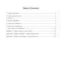
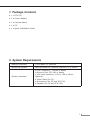
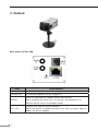
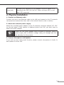
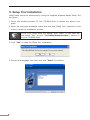
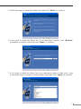
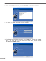
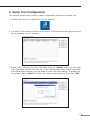
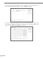
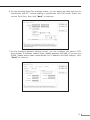
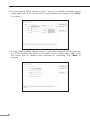
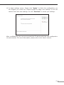
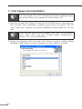
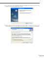
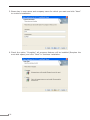
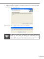
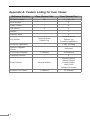
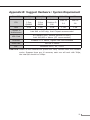
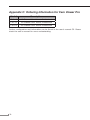
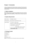
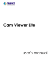
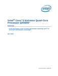
CCD Box PoE Internet Camera
ICA-700
Quick Installation Guide
Table of Contents
1. Package Contents......................................................................................... 3
2. System Requirements................................................................................... 3
3. Outlook........................................................................................................ 4
4. Physical Installation...................................................................................... 5
5. Setup Tool Installation................................................................................... 6
6. Setup Tool Configuration............................................................................... 9
7. Cam Viewer Lite Installation.........................................................................14
Appendix A: Feature Listing for Cam Viewer.......................................................18
Appendix B: Suggest Hardware / System Requirement.......................................19
Appendix C: Ordering Information for Cam Viewer Pro........................................20
1. Package Contents
● 1 x ICA-700
● 1 x Power Adapter
● 1 x Camera Stand
● 1 x CD
● 1 x Quick Installation Guide
2. System Requirements
Network Interface
10/100Base-TX Ethernet
Monitoring System
Recommended for Internet Explorer 6.0 or above
System Hardware
● CPU: Pentium 4, 1.5GHz or above
● Memory Size: 512 MB or above
● VGA card resolution: 1024 x 768 or above
Optional:
● Sound Card (for PC)
● Microphone (for PC and ICA-700)
● Speaker (for PC and ICA-700)
3. Outlook
Rear panel of ICA-700
Port
Description
AUDIO IN
An external microphone can be plugged in.
AUDIO OUT
An external speaker can be plugged in.
RESET
Reset to manufacturer default valued and reboot.
When pressed and held over 10 seconds, the settings of IP
Camera will be set to the default values.
DC 12V
Connect the supplied power adapter.
When this device is obtaining power from PoE, you don’t have to
attach the power adapter.
LAN (PoE)
Connect your Camera to a 10/100Base-TX hub or switch. It is
compliant with IEEE 802.3af PoE. Either mid-span PSE or endspan PSE supported.
4. Physical Installation
1. Connect an Ethernet cable
Connect one end of an Ethernet cable to the LAN port located on the IP camera’s
rear panel and connect the other end to the network device (hub or switch).
2. Attach the external power supply
Attach the provided power adapter to the IP camera’s connector labeled “DC 12V”
on the rear panel. If this camera is obtained power from PoE, you don’t have to
attach the power adapter.
Note
Please use the power adapter that is bundled in package. Using a
power supply with a different voltage rating will damage and void
the warranty for this product.
3. Connect Microphone and Speaker
If you will use the 2-Way audio function, please connect microphone to Audio In
and speaker to Audio Out.
5. Setup Tool Installation
Initial setup should be performed by using the supplied Windows-based Setup Tool
as follows:
1.Insert the bundled product CD into CD-ROM drive to launch the autorun program.
2.When the web page displayed, select and click the “Setup Tool” hyperlink on the
menu to start the installation process.
Note
If the CD’s menu does not appear, click “Start” on the task bar
and select “Run” to type “X:\Utility\SetupTool.exe”, assume X
is your CD-ROM drive
3.Click “Yes” to start the Setup Tool Installation.
4.Choose the language you need, and click “Next” to continue.
5.Follow the step for install the Setup Tool, and click “Next” to continue.
6.If you wish to install the Setup Tool in an alternative location, click “Browse”
and define a location; otherwise click “Next” to continue.
7.If you wish to install the Setup Tool in an alternative folder of start menu, type
a new folder name or select a exiting folder; otherwise click “Next” to continue.
8.Check the installation summary, and click “Install” to start the installation.
9.The Setup Tool will be start install to your computer.
10.The Setup Tool installation successful. Click “Finish” to complete the installation. If you would like to run the Setup Tool, please check “Launch Program
file” before click Finish button.
6. Setup Tool Configuration
This section shows how to perform basic configuration functions by Setup Tool.
1.Double click the icon of Setup Tool on the desktop.
2.The Setup Tool screen will show up as below. It will automatically search and list
the IP cameras on your network.
3.Select the IP camera you want, and then click the “Setup” button on the right
side. The login window will pop up. If the Administrator User Name and Password have been changed, you will need to enter the new settings. In default values, please enter “admin” for both User Name and Password. Then click “OK”.
4.On the following System information screen, it displays the Product Name, Firmware Version and Hardware Version. Click on “Next” to continue.
5.On the following Account settings screen, you can modify the Administrator login
user name and password. And you can add some user accounts as Admin, Operator or Viewer. Please click “Next” to continue.
10
6.On the following Date/Time settings screen, you can adjust the date and time to
synchronize with PC, manual setting or synchronize with NTP server. Select the
correct Time Zone, then click “Next” to continue.
7.On the following Network settings screen, you can configure the device HTTP
port number, IP address, subnet mask, default gateway and DNS. If you are use
PPPoE, please select obtain automatically for IP address and DNS settings. Click
“Next” to continue.
11
8.On the following PPPoE settings screen, if you are use PPPoE connection, please
select “On” and fill the correct User ID and Password for dialling. Click “Next”
to continue.
9.On the following DDNS settings screen, if you have registered the account from
the DDNS provider and want to use DDNS function, please select “On” to fill
the correct User ID, Password and Hostname for connecting. Click “Next” to
continue.
12
10.In Apply settings screen. Please click “Apply” to finish the configuration, we
will suggest you check the “Reboot system to apply new settings” to let the
camera work with new settings. Or click “Previous” to check your settings.
After modifications, you may now connect the IP camera with the new configuration
via web browser. For more information, please refer to the User’s manual.
13
7. Cam Viewer Lite Installation
Note
The Cam Viewer Lite / Pro 30 days trial version installation steps
are similar. Below is the installation of Cam Viewer Lite.
1.Insert the bundled Cam Viewer CD disk into the CD-ROM drive to launch the autorun program. Once completed, a welcome menu screen will appear. Click the
“Cam Viewer Lite” hyperlink, the below InstallShield Wizard dialog box will appear.
Note
If the welcome screen does not appear, click “Start” at the taskbar.
Then, select “Run” and type “X:\Cam Viewer Lite\setup.exe”,
assume “X” is your CD-ROM drive.
2.Selects the language which you want, Cam Viewer is current including fifteen
languages. Please select one of the language and click ”Next” to continue.
14
3.The “Welcome to the InstallShield Wizard for Planet Cam Viewer Lite 1.0.3” will
display on the screen, please click “Next”.
4.Please read the license agreement and then check “I accept the terms of the
license agreement” if you are agreed and click “Next” to continue the installation
15
5.Please key in user name and company name for which you want and click “Next”
to continue installation.
6.Check the option “Complete”, all program features will be installed (Requires the
most disk space) and click “Next” to continue installation.
16
7. “Ready to Install the Program” will appear to prompt you to start the installation. Please click “Install” to start.
8.Please click “No” to finish the Cam Viewer Lite installation.
Note
In above step, when Cam Viewer works with MBM5 (Motherboard
Monitor 5), Cam Viewer will display CPU temperature and fan
speed. Please click “Yes” if you need this function and refer to the
manual of Cam Viewer CD disk for complete installation.
17
Appendix A: Feature Listing for Cam Viewer
Software Version
Cam Viewer Lite
Cam Viewer Pro
32
16 / 32 / 64
Dual Monitor
-
V
Smart Guard
-
V
I/O Device
V
V
Hotline
-
V
Address Book
-
V
Unusual event
System log
Unusual event
System log
Counting application
Counting Application
-
2 way counting
Remote Playback
Server
-
Unlimited
1 Channel
16 Channels
-
V
General Motion
General Motion
Missing Object
Foreign Object
Lose Focus
Camera Occlusion
1 Channel
16 Channel
IP Camera Input
Log Viewer
Concurrent Playback
Counting Function
Smart Search
Remote Live Viewer
18
Appendix B: Suggest Hardware / System Requirement
Total FPS
~600
600~480
480~240
240~120
120~
CPU
Intel Core
2 Duo
QX6800
Intel Core
2 Duo
E6600
Intel
Pentium D
930
Intel P4
3.0
Intel P4
2.8
RAM
4 GB
2 GB
2 GB
1 GB
1 GB
Chipset of
Motherboard
Intel 946 or 965 chip, Intel Chipset recommended
VGA Card
ATI Radeon 9200, nVIDIA GeForce FX-5200,
Intel 945/965 or above (ATI recommended)
Ethernet
100Base-TX or Above, Gigabit LAN recommended
Hard Disk
160 GB or above
O.S.
Windows 2000 / XP / 2003
Total FPS: Means all the cameras will spend how many frames when this software
works. Suppose there are 10 cameras, each one will work with 30fps,
the total fps should be 300fps.
19
Appendix C: Ordering Information for Cam Viewer Pro
Model
Description
CVP-16
16-Channel Cam Viewer Professional
CVP-32
32-Channel Cam Viewer Professional
CVP-64
64-Channel Cam Viewer Professional
Further configuration and information can be found in the user’s manual CD. Please
check the user’s manual for more understanding.
20