1
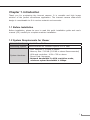
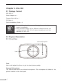
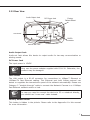
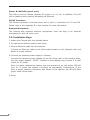
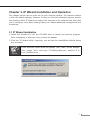
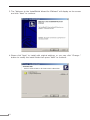
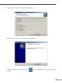
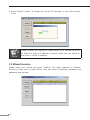
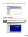
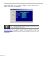
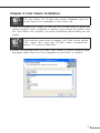
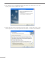
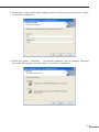
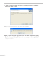
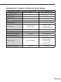
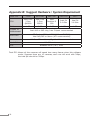
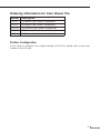
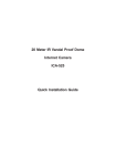
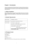
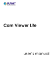
CMOS Box Internet Camera
ICA-120
Quick Installation Guide
Table of Contents
Chapter 1. Introduction..................................................................................... 3
1.1 Before Installation.................................................................................. 3
1.2 System Requirements for Viewer............................................................. 3
Chapter 2. ICA-120........................................................................................... 4
2.1 Package Content.................................................................................... 4
2.2 Physical Description............................................................................... 4
2.2.1 Front View.................................................................................. 4
2.2.2 Rear View................................................................................... 5
2.2.3 Installation Steps......................................................................... 6
Chapter 3. IP Wizard Installation and Operation.................................................. 7
3.1 IP Wizard Installation............................................................................. 7
3.2 Wizard function....................................................................................10
3.3 Username and Password ......................................................................11
Chapter 4. Cam Viewer Installation...................................................................13
Appendix A: Feature Listing for Cam Viewer .....................................................17
Appendix B: Suggest Hardware / System Requirement.......................................18
Ordering Information for Cam Viewer Pro..........................................................19
Further Configuration..................................................................................19
Chapter 1. Introduction
Thank you for purchasing the internet camera. It is versatile and high image
solution of the perfect surveillance application. The internet camera state-of-art
design is considerable to fit in various network environments.
1.1 Before Installation
Before installation, please be sure to read this quick installation guide and user’s
manual (CD) carefully to complete machine installation.
1.2 System Requirements for Viewer
Network Interface
10/100MBase-TX Ethernet
Monitoring System
Recommended for Internet Explorer 6.0 or later
System Hardware
·
·
·
·
·
CPU: Pentium 4, 1.5GHz or above
Memory Size: 512 MB (512 MB or above Recommended)
VGA card resolution: 1024 x 768 or above
Sound Card: Necessary
Network bandwidth: In VGA resolution mode,
minimum upload bandwidth is 1Mbps.
Chapter 2. ICA-120
2.1 Package Content
ICA-120 x 1
Power Adapter x 1
Camera Mount Kit x 1
CD Disk x 1
Quick Installation Guide x 1
Note
1. If any of the above items are missing, please contact your
dealer immediately.
2. Using a power supply with a different voltage that the one
included with the ICA-120 will cause damage and void the
warranty for ICA-120.
2.2 Physical Description
2.2.1 Front View
Internal Microphone
Lens
Lens
User could adjust the focus to get the best picture quality.
Internal Microphone
The Camera has built-in an internal microphone. This microphone is hidden in the
pinhole located on the front panel
2.2.2 Rear View
Audio Output Jack
DC Power Jack
Factory
Default Reset
LAN Socket
DI/DO
Connector
External MIC Jack
Power & LAN LED
Audio Output Jack
Audio-out Jack allows this device to output audio for two-way communication or
alerting sound.
DC Power Jack
The input power is 12VDC.
Note
Only use the power adapter supplied with ICA-120. Otherwise, the
product may be damaged.
LAN Socket
The LAN socket is a RJ-45 connector for connections to 10Base-T Ethernet or
100Base-TX Fast Ethernet cabling. This Ethernet port built N-Way protocol can
detect or negotiate the transmission speed of the network automatically. Please use
Category 5 “straight through” cable to connect the Network Camera to a 100Mbps
Fast Ethernet network switch or hub.
Note
In case you need to connect the device to PC or notebook directly,
you should use “cross-over” cable instead.
Factory Default Reset
This button is hidden in the pinhole. Please refer to the Appendix A in this manual
for more information.
Power & LAN LED (green color)
This LED is used to indicate whether DC power is on or not. In addition, this LED
will be flashing while network accessing via Ethernet.
DI/DO Connector
The Camera provides a terminal block with 4 pins of connectors for DI and DO.
Please refer to the Appendix B in this manual for more information.
External Microphone
The Camera also supports external microphone. User can plug in an external
microphone to pick up voice more.
2.2.3 Installation Steps
1.Attach the Camera with the included stand
2.Fix camera to desired location with stand
3.Plug an Ethernet cable into the Camera
Connect an Ethernet cable to the LAN socket located on the camera’s rear and
attach it to the network.
4.Connect the external power supply to Camera
Connect the attached power adapter to the DC power jack of the camera. Note:
Use the power adapter, 12VDC, included in the package and connect it to wall
outlet for AC power.
Once you have installed the camera well and powered it on, the power LED will
turn on. It means the system is booting up successfully. Furthermore, if you
have a proper network connection, and access to the camera, the LED will flash
green under wired mode.
5.Done
Chapter 3. IP Wizard Installation and Operation
This chapter shows how to quick set up your internet camera. The internet camera
is with the default settings. However to help you find the networked camera quickly
the windows utility-IP Wizard can search the cameras in the network that shall help
you to configure some basic setting before you started advanced management and
monitoring.
3.1 IP Wizard Installation
1.Insert the bundled CD into the CD-ROM drive to launch the autorun program.
Once completed, a welcome menu screen will appear.
2.Click the “IP Wzard Utility” hyperlink; you will see the InstallShield Wizard dialog
box as below.
Note
If the welcome screen does not appear, click “Start” at the taskbar.
Then, select “Run” and type “D:\Utility\setup.exe”, assume D is
your CD-ROM drive.
3.The “Welcome to the InstallShield Wizard for IPWizard” will display on the screen
and click “Next” to continue.
4.Please click “Next” to install with original settings, or you may click “Change…”
button to modify the install folder then press “Next” to continue.
5.Please click “Install” to start the installation.
6.Please click “Finish” to complete the installation
7.Please double-click the utility icon
utility.
on the desktop then you will see the
8.Press “Search” button. IP Wizard will list all IP Cameras in your LAN environment:
Note
Please connect you camera or video server to PC directly, and use
IP Wizard to search IP address of device, when you use device at
first time or forget IP address.
3.2 Wizard function
Please select your device and press “Wizard”. The utility featured of “Wizard”
function to help user to initial device. User can setup IP address, username and
password step by step.
10
Please enter User Name and Password. Default Username is: admin, leave
password blank. Then click “Submit”.
3.3 Username and Password
You may change the ID and assign a new password to your device or keep the
original and press “Next” to continue.
Note
If you assign new password to your device, please write down and
avoid forgetting it.
11
You can select “Static IP” and enter the IP settings. Or select “DHCP ON” when
there is a DHCP server in your network.
Note
If no IP address is assigned after 30 seconds, Internet Camera will
use its default address 192.168.0.20.
User may open the web browser, and key in the IP address (for example:
http://192.168.0.20, the default IP address) in the address field to login web
configuration page and refer to the User’s manual in the bundled CD disk for more
configuration.
12
Chapter 4. Cam Viewer Installation
Note
The Cam Viewer Pro 30 days trial version installation steps are
similar. Below is the installation of Cam Viewer Lite.
1.Insert the bundled Cam Viewer CD disk into the CD-ROM drive to launch the
autorun program. Once completed, a welcome menu screen will appear. Click
the “Cam Viewer Lite” hyperlink, the below InstallShield Wizard dialog box will
appear.
Note
If the welcome screen does not appear, click “Start” at the taskbar.
Then, select “Run” and type “D:\Cam Viewer Lite\setup.exe”,
assume “D” is your CD-ROM drive.
2.Selects the language which you want, Cam Viewer is current including fifteen
languages. Please select one of the languages and click”Next” to continue.
13
3.The “Welcome to the InstallShield Wizard for Planet Cam Viewer Lite 1.0.3” will
display on the screen, please click “Next”.
4.Please read the license agreement and then check “I accept the terms of the
license agreement” if you are agreed and click “Next” to continue the installation
14
5.Please key in user name and company name for which you want and click “Next”
to continue installation.
6.Check the option “Complete” – all program features will be installed (Requires
the most disk space) and click “Next” to continue installation.
15
7.“Ready to Install the Program” will appear to prompt you to start the installation.
Please click “Install” to start.
8.Please click “No” to finish the Cam Viewer Lite installation.
9.Note: In above step, when Cam Viewer works with MBM5 (Motherboard Monitor
5), Cam Viewer will display CPU temperature and fan speed. Please click “Yes”
if you need this function and refer to the manual of Cam Viewer CD disk for
complete installation.
16
Appendix A: Feature Listing for Cam Viewer
Software Version
Cam Viewer Lite
Cam Viewer Pro
32
4 / 8 / 16 / 32 / 64
-
V
Smart Guard
-
V
I/O Device
V
V
Hotline
-
V
Address Book
-
V
Unusual event
System log
Unusual event
System log
Counting application
-
2 way counting
IP Camera Input
Dual Monitor
Log Viewer
Counting Application
Remote Playback Server
Concurrent Playback
Counting Function
Smart Search
Remote Live Viewer
-
Unlimited
1 Channel
16 Channels
-
V
General Motion
General Motion
Missing Object
Foreign Object
Lose Focus
Camera Occlusion
1 Channel
16 Channel
17
Appendix B: Suggest Hardware / System Requirement
Total FPS
~600
600~480
480~240
240~120
120~
CPU
Intel Core
2 Duo
QX6800
Intel Core
2 Duo
E6600
Intel
Pentium D
930
Intel P4
3.0 GHz
Intel P4
2.8 GHz
RAM
4 GB
2 GB
2 GB
1 GB
1 GB
Chipset of
Motherboard
VGA Card
Ethernet
Hard Disk
O.S.
Intel 946 or 965 chip, Intel Chipset recommended
ATI Radeon 9200, nVIDIA GeForce FX-5200,
Intel 945/965 or above (ATI recommended)
100 Base-TX or Above, Gigabit LAN recommended
160 GB or above
Windows 2000 / XP / 2003
Total FPS:Means all the cameras will spend how many frames when this software
works. Suppose there are 10 cameras, each one will work with 30fps;
the total fps should be 300fps.
18
Ordering Information for Cam Viewer Pro
Model
Description
CVP-4
4-Channel Cam Viewer Professional
CVP-8
8-Channel Cam Viewer Professional
CVP-16
16-Channel Cam Viewer Professional
CVP-32
32-Channel Cam Viewer Professional
CVP-64
64-Channel Cam Viewer Professional
Further Configuration
If you want to configure more detail settings of ICA-120, please refer to the user
manual in the CD disk.
19
This page is intentionally left blank