1
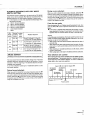
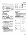
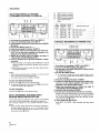
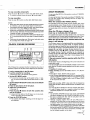
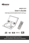
3
STEREO
DOUBLE
CASSETTE
i tJlc
DECK
CT-W803RS
CT-W703RS
CT-W603RS
•
The above illustration
•
For the demo function, refer to back cover of this operating instructions.
shows CT-W803RS.
Thank you for buying this Pioneer product.
Please read through these operating instructions so you will
know how to operate your unit properly. After you have
finished reading the instructions, keep the manual in a safe
place for future reference.
[For
Canadian
model]
CAUTION:To
PREVENT
ELECTRIC
SHOCK
In some countries or regions, the shape of the power plug and
power outlet may sometimes differ from that shown in the
ATTENTION:PouR
explanatory drawings. However, the method of connecting and
operating the unit is the same.
PREVENIR
LES
"This product complies with the Radio Interference
The serial number
panel.
require- I
ments of the EC (European Community) Directive 8713081EEC." J
models]
for this equipment
CHOCS
ELECTRIQUES NE PAS UTILISER CETrE FICHE POLARISEE
AVEC UN PROLONGATEUR
UNE PRISE DE COURANT
OU
UNE AUTRE SORTIE DE COURANT,
SAUF Sl LES LAMES
PEUVENT
ETRE INSEREES
A FOND SANS EN LAISSER
AUCUNE PARTIE A DECOUVERT.
YV/-_RIMIIMI,.1;TO
PREVENT
FIRE OR SHOCK HAZARD, DO NOT EXPOSE THIS APPLIANCE
TO RAIN OR
MOISTURE.
IMPORTANT
NOTICE
[For U.S. and Canadian
DO
NOT USE THIS (POLARIZED)
PLUG WITH AN EXTENSION
CORD. RECEPTACLE
OR OTHER OUTLET UNLESS THE
BLADES CAN BE FULLY INSERTED TO PREVENT BLADE
EXPOSURE.
is located
on the rear
Please write this serial number on your enclosed war-
ranty card and
security.
keep
it in a secure
area. This
is for your
IMPORTANT 1
CAUTION
The lightning
triangle,
uninsutated
flash
with
is intended
"dangerous
arrowhead,
to alert
the
voltage"
within
user
to the
within
enclosure that may be of sufficient
magnitude
a risk of electric shock to persons,
an equdateral
presence
the
product's
to constitute
CAUTION:
of
TO
NOT
PREVENT
THE
REMOVE
SERVICEABLE
QUALIFIED
RISK
COVER
PARTS
SERVICE
OF
ELECTRIC
(OR
INSIDE.
SHOCK,
BACK).
REFER
NO
SERVICING
PERSONNEL.
PIONEER"
The Art of Entertainment
DO
USERTO
The exclamation
intended
to alert
operating
the
point
w_thln an equilateral
triangle
is
the user to the presence
of important
and maintenance
literature
accompanying
(servicing)
the
instructions
appliance.
in
IMPORTANT
2
The cut-off
be inserted
in electric
tion panel
colours of
FOR USE IN THE UNITED
KINGDOM
The
wires
in this
accordance
mains
lead
with the following
blue
neutral
brown
live
are
coloured
Do not connect
plug should be disposed of and must not
into any 13 amp socket as this can result
shock. The plug or adaptor or the distribu
should be provided with 5 amp fuse. As the
the wires in the mains lead of this ap-
three
in
If the plug provided
is unsuitable for your socket
outlets, the plug must be cut off and a suitable plug
fitted.
of a
NOTE
After replacing or changing • fuse,the fuse cover in the
plug mus_ be replaced with a fuse cover whic_
corresponds to the colour of the insert in the base of
the plug or the word that is embossed on the base of
the plug, end the applia rice must not be used without e
fuse cover. If lost, replacement
fuse covers can be
obtained from your dealer.
Only 5 A fuses approved by B.S.I. or A.S.T.A. to B.S.
1362 should be used.
pliance may not correspond with coloured markings
identifying the terminals in your plug, proceed as follows:
The wire which is coloured blue must be connected to
the terminal which is marked with the letter N or
coloured black.
code:
either wire to the earth terminal
pin plug.
The wire which is coloumd brown must be connected
to the terminal which is marked with the letter L or
coloumd red.
SAFETY INSTRUCTIONS
READ
INSTRUCTIONS
instructions
-
should
All the
be read
and
the
POWER
operating
appliance
-
The
should
safety
be
and
retained
operating
for
future
the
operating
instructions
FOII__OW
INSTRUCTIONS
instructions
should
WATER
AND
MOISTURE
LOCATION
-
stable
WALL
or
-
appliance
OR
not
pool,
surface
that may
placed
in • built-in
or cabinet that
the ventilation
The
in a
with
be situated
away
heat
SOURCES
-
to
•
in
the
be routed
walked
on
against
them.
or
The
power
convenience
exit
with
the following
-
by
are
not
items
If
the
feature.
safety
a polarized
power
ANSI/NFPA
or qualified
service
or
appliance
authorized
personnel
cord
respect
the
to
when:
plug
have
appliance
The
or
has
been
appliance
exhibits
has been
exposed
does not appear
a marked
appliance
has
The
appliance
operating
liquid
change
been
user
been
spilled
should
instructions.
to
qualified
or the
All other
service
-
location
This
to
only one
are unable
try
the
still fail to fit, contact
obsolete
outlet.
of the
clean
with
other
volatile
furniture
liquids
with care.
normally
Oo
servicing
in
since
benzine,
they
defeat
J
WIRE
GROUND
at
ANTENNA
(NEC
SECTION 810 -- 20)
is
I
ELECTRIC
SERVICE
I
I
DISCHARGE UNIT
GROUNDING CONDUCTORS
plug
CLAMPS
(NEC SECTION 810 -- 21)
If the
to
POWER SERVICE GROUNDING
the
ELECTRODE
FIG. A
insecticides
may
corrode
and
wire
grounding
discharge
electrodes,
electrode.
unit,
See
and
Fig.
end
cart combination
Quick stops,
excessive
the
appliance
should
force,
be
and
and cart
personnel.
This is a
the
cleaned
cloth.
lead-in
of
the
read
plug.
not
with
mast
should
ANTENNA
or
plug.
be
dw
to
surges
to service
described
point
your electrician
polarized
wax,
way.
the
be
as
Electrical
the
of the
antenna
uneven
surfaces
may cause
combination
to overturn.
LEAD IN
is equipped
to insert
reversing
National
size
to
grounding
for the grounding
be
upon
please
product
so
voltage
of
unit,
of
outside
terminal,
information
grounding
discharge
An appliance
moved
as
product
plug,
of the
provides
grounding
structure,
antenna
If an
enclosure
not attempt
that
-
is grounded
A.
into
rain.
to operate
810
70,
proper
connection
requirements
in performance.
dropped
beyond
to
an
section
conductors,
has
CART
appliance.
The
The
fallen,
to
supporting
service
cords
likely
and
power
outlet
If you
outlet,
your
<RRB1143>
U.S.A.
Code,
type
or
to cords
purchased
- The appliance
should
a polishing
cloth or a soft
2
En
the
purpose
cabinet.
In the
be
appliance.
your
instructions.
will fit into the
replace
taken
are not spilled
should
NEC --
with s polarized
alternating
current line plug (a plug
having
one blade wider
than the other).
This plug
should
Care
system
antenna
provide
some
protection
against
and built-up
static charges.
be
the
placed
attention
receptacles,
from
of
Power-supply
they
pinched
they
plug
-
antenna
to the
when
left
the
from
should
only
instructions
Pay particular
where
into
of time.
GROUNDING
is connected
sure
amplifiers)
appliance
supply
operating
so that
plugs,
POLARIZATION
fully
period
ENTRY
do not fall and liquids
power-supply
ANTENNA
appliance
registers,
(including
on the appliance.
PROTECTION
should
safety
outlet
by a Pioneer
be referred
of air through
the
be serviced
the
the
or.
as s bookcase
from
through
openings.
SERVICE
The
damaged.
SERVICING
-
or similar
such
radiators,
•
appliance
openings;
OUTDOOR
be located
of the
heat.
described
provided
tt.e
cord
enclosure
REQUIRING
Objects
or
so
the flow
appliances
connected
marked
IqDWlER-CORD
as
•
situated
not interfere
ventilation
should
such
appliance
be
sofa, rug,
installation,
appliance
produce
POWER
does
block the
or other
The
The
should
antenna
power
damaged.
or ceiling.
For example,
on a bed,
may impede
openings.
sources
stoves,
CLEANING
with
•
•
installed
should
or position
ventilation.
not be situated
heat
-
to a wall
appliance
the
a long
MQUID
objects
center
not
etc.
be
MOUNTING
The
its location
should
that
should
near e bathtub,
tub, in a wet
should
be mounted
-
its proper
-
use
•
CEIMNG
should
HEAT
into
DAMAGE
antenna
lines.
- The
unplugged
for
AND
should
appliance
s swimming
to.
and
be
so that
location.
VENTILATION
that
The
end in
be adhered
for example,
sink, laundry
near
The
should
All operating
be followed.
be used near water
washbowl,
kitchen
basement,
on the appliance
An outdoor
power
PERIODS
unused
OBJECT
-- All warnings
-
from
should
reference.
HEED WARNING
ONES
away
is
NONUSE
operated.
RETAIN
INSTRUCTIONS
instructions
safety
before
only
Never
or
the
SYSTEM
(NEC ART 250, PART H)
NATIONAL
ELECTRIC CODE
This
equipment
has been tested
limits
are designed
uses,
and can
interference
to provide
radiate
to radio
radio
and found
reasonable
frequency
communications.
to comply
with the limits for a Class
protection
against
energy
and,
However,
harmful
if not installed
there
and
is no guarantee
used
or relocate
--Increase
the separation
between
--Connect
the equipment
into
--Consult
I
the dealer
the receiving
device,
pursuant
in a residential
in accordance
that interference
equipment
does cause harmful interference
to radio or television
reception,
the user is encouraged
to try to correct
the interference
by one or more
-Reorient
B digital
interference
with
will
to Part 15 of the FCC Rules. These
installation.
the
not occur
which can be determined
of the following
measures:
This equipment
instructions,
may
in a particular
by turning
generates,
cause
installation.
the equipment
harmful
If this
off and on,
antenna.
the equipment
an outlet
or an experienced
and receiver.
on a circuit different
radio/TV
technician
from
that to which the receiver
is connected.
for help.
I
Alteration
Informationor modifications
to User
carried out without appropriate authorization may invalidate the user's right to operate the equipment.
[For Canadian
model]
This digital apparatus
dio Interference
[Pour
does not exceed
Regulations
le modble
the Class B limits for radio noise emissions
of the Canadian
Department
from digital apparatus
set out in the Ra-
of Communications.
Canadien]
L'interference, radio_lectrique g6n6r6e par cet appareil num_rique de type B ne d_passe pas les limites _nonc_es dans le
R6glement sur les perturbations radio61ectriques, section appareil num6rique, du Minist6re des Communications.
We Want
Used
lifetime
noise is
and the
You Listening
For
A Lifetime
wisely, your new sound equipment
will provide a
of fun and enjoyment.
Since hearing damage from loud
often undetectable
ur)til it is too late, this manufacturer
Electronic Industries
Association's Consumer Electronics
Group recommend you avoid prolonged
exposure to excessive
noise. This list of sound levels is included for your protection.
Selecting fine audio equipment
such as the unit you've just
purchased
is only the start of your musical enjoyment.
Now it's
time to consider how you can maximize the fun and excitement
your equipment
offers. This manufacturer
and the Electronic
Industries
Association's Consumer
Electronics
Group want you
to get the most out of your equipment
by playing it at a safe
level. One that lets the sound come through loud and clear
without annoying blaring or distortion--and,
most importantly,
without affecting your sensitive hearing.
Sound can be deceiving.
Over time your hearing "comfort
level" adapts to higher volumes of sound. So what sounds
"normal" can actually be loud and harmful to your hearing.
Guard against this by setting your equipment
at a safe level
BEFORE
your hearing adapts.
To establish
a safe level:
• Start your volume control at a low setting.
• Slowly increase the sound until you can hear it comfortably
and clearly, and without distortion.
Once you have established
a comfortable
• Set the dial and leave it there.
sound
Decibel
Level
3O
4O
5O
6O
7O
8O
Exam_m_p_le
Quiet library, soft whispers
Living room, refrigerator, bedroom away from traffic
Light traffic, normal conversation,
quiet office
Air conditioner
at 20 feet, sewing machine
Vacuum cleaner, hair dryer, noisy restaurant
Average city traffic, garbage disposals, alarm clock
at two feet.
THE FOLLOWING
NOISES CAN
UNDER
CONSTANT
EXPOSURE
90
100
120
140
180
Information
BE DANGEROUS
Subway, motorcycle, truck traffic, lawn mower
Garbage truck, chain saw, pneumatic
drill
Rock band concert in front of speakers, thunderclap
Gunshot blast, jet plane
Rocket launching
pad
courtesy
of the
Deafness
Research
Foundation.
level:
"IRking a minute to do this now will help to prevent hearing
damage or loss in the future. After all, we want you listening for
a lifetime.
ka,_m=.
3
<RRB1143>
En
I CONTENTS
i
INSTALLATION ................................................................................
MAINTENANCE ................................................................................
HANDLING CASSETTE TAPES .......................................................
CONNECTIONS ................................................................................
FRONT PANEL FACILITIES ................................................................
REMOTE CONTROL OPERATION (CT-W803RS only) ...................
PLAYBACK .......................................................................................
SINGLE PLAYBACK ....................................................................
BLANK SKIP ................................................................................
RELAY PLAYBACK .....................................................................
MUSIC SEARCH .........................................................................
RECORDING .....................................................................................
SINGLE RECORDING ..................................................................
RECORDING USING MICROPHONE
4
4
5
6
7
11
12
12
12
12
13
14
14
(CT-W803RS/CT-W703RS only) ................................................
RECORDING MUTE ....................................................................
ERASING A TAPE .......................................................................
AUTO BLE TUNING ....................................................................
RELAY RECORDING ...................................................................
PARALLEL RECORDING
14
14
14
15
16
MAINTENANCE
Capstan
Pinch
ro,,er
Rec/play
16
17
18
19
21
The
heads,
easily.
be cleaned
in locations
or near a space
heater
or other
damage
finish
or internal
may
subject
heating
also result
to direct
device,
sunlight,
humidity.
If the deck
is placed
up humming
large amount
•
If the deck
ference
the tape.
television
deck.
•
directly
as this may cause
is located
if the
If this
is installed
on top of an amplifier,
set, it may
will be recorded
happens,
set or turn
move
the
a cloth
in an ex-
it may
generates
pick
as a whistling
the deck
television
further
away
set off when
pick
a
up intersound
on
from
the
operating
over the deck,
or block
the ventilation
CONDENSATION
the deck
sation
is moved
the temperature
may
form
on the
from a cold location
of the
room
mechanical
changes
parts.
to a warm
location,
suddenly,
conden-
This can adversely
af-
fect the performance
of the deck. If this occurs, wait for about one
hour to allow the deck to adjust to the room temperature.
To prevent condensation
slowly.
4
<RRB1143>
En
when
to STANDBY.
pinch
the
rollers.
heating
a room,
raise the
do not load a tape
completely
(about
two
until the clean-
or three
minutes).
THE HEADS
1
using the
cassette
magnetized.
sounds
The
magnet
deck
for a period
same
or other
effect
magnetized
the heads become
will be lost during
noise may also occur.
recording
The heads
with a head demagnetizer,
stores.
object
or playback,
the
heads
will
if a magnetized
is brought
magnetized,
should
which
of time,
will occur
too close
high-frequency
and interference
be regularly
can be purchased
demagnetized
at most
audio
When demagnetizing
the heads, make sure that the POWER switch
of the cassette
deck is set to ON, and turn off the sound volume
on the amplifier
to which
no headphones
are connected.
the
operating
instructions
the deck
is connected.
For detailed
of the
head
Also be sure that
instructions,
refer
to
demagnetizer.
THE FRONT
PANEL
slots
function.
or when
of the
head sec-
the
in any way. The ventilation
slots on this deck are necessary
to
keep internal
parts cool. If they are blocked,
the deck may mal-
When
the
I
CLEANING
Do not place
that
to open the cassette
door.
in cleaning
fluid and use it to wipe
the head section,
to the heads. When
deck
near a television
which
and
has dried
screwdriver,
parts.
or other noise. Also, if the amplifier
of heat, the deck may malfunction.
noise,
capstans
cleaning
fluid
become
cessively
humid or dusty location. Avoid installing
the deck next
to kitchen counters
or other locations
subject
to oily smoke or
•
switch
button
swab
DEMAGNETIZING
After
Malfunctions
and the
in a deterioration
recommended
quite
regularly.
Press the eject
Dip a.cleaning
After
When installing the deck, avoid locations with high
temperatures
or humidity, and make sure that the
deck receives adequate ventilation.
•
dirty
the high fre-
will not be reproduced
resulting
It is therefore
1. Set the POWER
ing
to the
be impaired,
get dirty,
NO TE:
INSTALLATION
the deck
are likely to get
the heads,
of a recording
will
sound.
and capstans
particularly
components
playback
tion
parts,
balance
heads,
Do not install
head
/
./v_.,_.,
Capstan
J
"_"
Pinch roller
pinch rollers
If these
stereo
2.
3.
•
Eraseh
CLEANING THE HEADS, PINCH ROLLERS AND
CAPSTANS
quency
(CT-W803RS only) ......................................................................
CDoDECK SYNCHRO RECORDING ............................................
TAPE COPYING ................................................................................
TROU BLESHOOTING .......................................................................
SPECIFICATIONS .............................................................................
_l
temperature
Clean the deck regularly with a soft cloth. If the front panel
becomes soiled, moisten a soft cloth with a weak solution of neutral detergent (diluted in five to six parts water), wring the cloth
well, and wipe the panel clean. Never use volatile cleaners like
thinners, benzine or alcohol because they will damage the panel
finish.
THE POWER SWITCH IS SECONDARY CONNECTED AND
THEREFORE DOES NOT SEPARATE THE UNIT FROM MAINS
POWER IN STANDBY POSITION.
1
HANDLING
CASSETTE
TAPES
J CHECK
A
_
Turn pencil to
remove tape slack
Check
CASSETTE
the
following
BEFORE USE
items
before
loading
]
a cassette
tape:
Is the tape loose, or is some of the tape outside
cassette?
If some
the
roller.
el
For erasure
This will prevent
take up the
reel hole and
cassette
Tab
for
tapes
come
and
Are the accidental
These
tabs allow
erased
Side
cl
A
Tab
for
Side
B
with
adhesive
stick
a piece
When
If the
tape
properly,
of doubled
it after
or thick
paper
using the
important
cassette.
tabs intact?
recordings
the tab on the cassette
from
shell
the recording
using
TYPE
not to block
holes
over
1V (Metal)
or TYPE
the sensor
holes with
are blocked,
will not operate
tape
the
function,
tape
so
off, simply
hole (Fig.
the tape
being
is broken
!1 (High/CrO2)
the automatic
stopper
this stopper when
prevention
adhesive
and
insert a pencil into
Remove
to activate
shell,
and pinch
valuable
recordings
will not be erased by mistake.
To rerecord on a cassette whose tab has been broken
careful
Cover
capstan
A).
slack.
replace
When
(Fig.
a plastic
erasure
off (Fig. B), it is not possible
__
slack
with
you to prevent
accidentally.
the cassette
the
In such cases,
the tape from becoming
the cassette
outside
between
the tape from being supplied
the
loading
___
enter
the tape itself.
to prevent
remove
is loose or projecting
may not properly
may even damage
Some
prevention
of the tape
tape
the
C).
tapes,
be
(Fig. D, Fig. E).
selector
mechanism
correctly.
NO TES:
•
The accidental
located
•
erasure
is facing you.
When breaking
prevention
when
TAPE
SELECTOR
This cassette deck is equipped
tion which utilizes the sensor
tabs
mine the
type
the
recording
tape
tab for each
the side that
side is the one
you want
off the tab, do not use a magnetized
[ AUTOMATIC
Erasure
prevention
on the top left
of tape
to protect
screwdriver.
FUNCTION
]
with an automatic tape selector funcholes on the tape cassette to deter-
being used.
The
deck is then
set to match
bias and equalization.
NO TES:
•
When using
have sensor
•
Make sure that the sensor holes on the cassette
otherewise
TYPE IV
holes.
i
Sensor
TYPE
holes
IV
_l
(Metal)
•
tape
properly.
Do not use TYPE
•
slack.
dirt,
•
•
(High/CrO2)
tape
I1! (FeCr)
sure that
mechanism
the tapes
are not blocked;
will
not
function
tapes.
I
TAPES
before starting
to record,
to allow the leader
the recording
head.
Do not leave a cassette
tape
Store the cassette
in its case
do not
il
selector
make
Leader tape (which cannot be recorded
on) is provided
at the
beginning
of a cassette tape. Let the tape run for about 5 seconds
TYPE
tape
tapes,
I TIPS ON CASSETTE
•
Sensorl,__holes
the
(Metal)
adhere
Store
to
tapes
oil, heat
the
tape,
exposed
to the environment.
after use so that dust and dirt
and
in a location
so the
free
problems
such as irregular
with
deck.
If cassette
tapes
in the rollers.
deck.
If you
will
magnetism,
not
get
dust,
are irregularly
wound,
damage
the
or rewind
tape
they can easily jam in the
often are subject to other
winding.
This can cause
are not certain
fast forward
sure that
tape
from
and humidity.
Because C-120
tapes are very thin,
pinch rollers and capstan,
and they
this
tape to clear
whether
It is best not to use them
the tape may get jammed
to both
the tape
the tape from beginning
is properly
the tape
and the
is wound
evenly,
to end, to make
wound.
5
<RRB1143_
En
I
CONNECTIONS
Compact
Disc Player
L?-Th
only)
Recording
d
REC
PLAY
I _Y"
Io0oO_l
/
Stereo
TAPE
jacks
Read through
•
nents which you intend to connect to this unit.
Turn the power on only after making all the connections.
the operating
•
Make
sure that
Amplifier
CONTROL
OUT jack
REC/PLAY
•
instructions
all of the connection
ly, as improper
jack
CD' DECK SYNCHRO
control
cord
connection
cord
_
connections
of the stereo
plugs are inserted
may generate
NO TES:
compo-
•
Keep the input and output jacks connected
fier and this unit, otherwise,
the CD•DECK
secure-
noise.
•
Left
AND
I
I
ing cannot
be carried
Even
the CD player
when
White
CONTROL
plug
Remote
CONTROL
jack
OUT
Control).
the TAPE jacks
Pioneer system
•
Be sure to connect
Right
(output)
the
the
channel
REC
(INPUT)
jacks of the amplifier,
jacks
designed
of the
and the PLAY
White
--
with an
or this
deck
Intermediary
plug
the
CONTROL
oneer
deck
PIONEER
bears
the
System
Re-
this unit
using the
control
unit does
If the remote
I and deck II, or a selection
II, the
buttons
a remote
cassette
but-
will only operate
control
decks,
unit
which
see page
deck
was
not
8.
OUT jack
jack
which outputs
of this unit to the
Red plug
unit.
for deck
I with
with
this jack to the
which
be able to operate
control
I or deck
for double
CONTROL
jacks of the amplifier.
plugs properly:
--
channel
I1. To operate
to the LINE jacks of the
to connect
component
it is equipped
buttons
deck
Cord
another
that
remote
not have separate
jacks of the deck to the play (input)
Connect
Left
of your amplifier
Control
of
You will then
ton to choose
(OUTPUT)
to the amplifier
IN jack
Use the enclosed
mote
channel
Red plug
deck.
is connected
PIONEER SYSTEM REMOTE CONTROL
(CT-W703RS/CT-W603RS
only)
mark (indicating
deck to the recording
out.
channel
(_
Right
between
the ampliSYNCHRO
record-
optical fiber cable, connect the CD player to the amplifier
unit with the input and output cords with pin plug.
I
CONNECTING
THE RECORDING
PLAYBACK CORDS
cassette
SYNCHRO
t
cord
Connect
JCD_
System
input
IN jack
Remote
signals from the CONTROL
jack of another
of another
unit.
component
Connect
IN jack
this jack to
compatible
with
Pi-
Control.
NO TE:
i CDoDECK
•
SYNCHRO
RECORDING
CDoDECK
SYNCHRO
recording
can be carried out when this
unit is connected
to a Pioneer CD player equipped
with a
CDoDECK
SYNCHRO
Connect the CDoDECK SYNCHRO jack of this unit to the CDoDECK
SYNCHRO jack of the CD player using the supplied CDo DECK SYNCHRO control cord.
<RRB1143>
En
Be sure to connect
both
of the control
CONTROL
IN and CONTROL
end of the cable.
cord's
OUT jacks.
plugs securely
Do not connect
to the
only one
jack.
Connection
6
1
I CONNECTING
Insert
the power
outlet
of your
THE POWER CORD
cord of the cassette
amplifier,
or into
deck
a normal
I
into the accessory
household
outlet.
AC
LFRONT PANEL FACILITIES
The illustration
shows
model
CT-W803RS.
sensor
@ ®
®®®
(CT-W803RS
only)
®®@@@
@
@
PlOf_JER
L
<::3 Aulro
I_liVIInllll
[::>
12,0LBY S NR / SUPER AUTO BLE
O POWER STANDBY/ON
The
POWER
switch
Even when
a power
the switch
the secondary
is in the STANDBY
flow to the deck's
connected
to a power
@ DECK I eject button (_)
switch/indicator
activates
circuits
transformer
position,
there
as long as the power
only.
a
will be
cord is
outlet.
DECK
I counter
reset
<_) DECK
I counter
mode
DECK
I BLE
®
DOLBY
(_
(CT-W803RS
LEL
NR
button
pressing
(RESET)
button
ON/OFF
switch
only)
Parallel
Normal:
only
Normal
recording
) Synchro
speed
button
(PARAL-
copy
button
(COPY
I •
II)
Dolby
noise
copy
reduction
manufactured
under
Corporation.
•
"'DOLBY",
marks
HX
and
license
HX
of Dolby
Pro originated
headroom
Laboratories
extension
Laboratories
by Bang
Dr]
LicetTsing
& Olufsen.
(COPY
I•
Licensing
Corporation.
@
@
@
Synchro
copy
buttons
II)
: Normal
speed
copy
HIGH
: Double
speed
copy
only
Double
) Synchro
speed
copy
button
(COPY
DECK
II counter
mode
DECK
II counter
reset
CDeDECK
: Fast
•
• •/MS
: Stop
: Fast forward/music
SYNCHRO
winding,
this button.
I •
II)
button
button
recording
button
(CD
reverse/music
O
: Recording
II
: Pause
•
: Recording
search
search
mute
jack (MIC)
(CT-W803RS/CT-W703RS
(U.S. and Canadian models only))
MIC LEVEL control (CT-W803RS/CT-WT03RS
(U.S.
and Canadian models only))
Headphones jack (PHONES)
Recording level control (REC LEVEL)
DECK II eject button ( _--)
If the
tape
press
ff the power
pressing
@ DECK II
is moving
the stop
is turned
remain
the eject
(recording,
(•)
button
winding,
this button.
is moving,
the cassette
on before
(Am) button.
operation
buttons
playback
: Forward playback
: Fast reverse/music
search
IHWMS
: Stop
: Fast forward/music
search
0
II
tape
pressing
In this case, turn the power
•_/MS
SYNC)
playback,
before
off while the tape
locked.
: Reverse
(TIME/COUNT)
(RESET)
playback
playback
for CT-W603RS]
door may
DECK II BLE button
@ Reverse mode switch (REV MODE RELAY/SKIP)
(_ DECK II BLE button (CT-W803RS/CT-W703RS)
(_
tape
pressing
(Am) button.
• </MS
etc.),
NO TE:
copy
(_
the eject
: Reverse
: Forward
•
NORMAL
(CT-W603RS
playback,
before
@ Microphone
@
and"HXPRO"aretrade-
display
(CT-W803RS/CT-W703RS)
HIGH:
Pro
from Dolby
thedouble-Dsymbol
Function
button
<1
•
[Except
® DOLBY* NR switch (B/C/S)
•
(recording,
@ Deck I operation buttons
(TIME/COUNT)
REC)
(CT-W603RS
is moving
ff the power is turned off while the tape is moving,
the cassette
door may remain
locked. In this case, turn the power on before
(Except for CT-W603RS)
button
tape
etc.), press the stop (n)
NO TE:
(_ FLEX button
(_
If the
: Recording
: Pause
mute
: Recording
7
<RRB1143>
En
FRONT
PANEL FACILITIES
REVERSE MODE
There
are three
SWITCH
the
switch
performed
position
is set to this
position,
on one side of the tape
the end of the side,
way mode _-_ position
When
the switch
the
end
tape
stops
first
of the
(forward)
side,
automatically
(auto
is
reaches
stop function).
playback
or recording
When
the tape
its direction
can
reaches
is automatically
function).
back
If playback
or re-
side, the tape will stop when
it
for playback,
repeatedly
until the
or until the tape has been played
automatically.
If the
playback
the beginning,
the
pause
and will
switch
button
is restarted,
both
stop
(i)
completely
is pressed
the repeat
play the tape
is set to this
sides of
button
15 times
position
with tapes,
Deck L
for
to pause
mode
15 times
are recorded
and then the tape stops,
two way mode.
If Deck I and II are loaded
the recording
starts with
In order
I FLEX (1If) SYSTEM
(16
•
the
tape,
over
from
both
sides
starts
(16 sides).
recording,
as described
above
for the
•
relay recording
is used when
•
DECK I
to operate
DECK I with
the remote
control
unit, adjust
the
unit as follows:
With the power off, press and hold the stop (i)
button of DECK I, and turn the power on. Continue
to hold the stop
(11) button
operated
for
approximately
using the remote
Switching
five
control
seconds.
DECK
unit, but DECK
I can
now
•
be
I! cannot.
to DECK II
To restore remote control operation
to DECK II, press the stop (e)
button of DECK II while DECK II is in stop mode. DECK II can now
be operated
using the
remote
control
unit. Remote
control
NO TE:
failure
or a sudden
change
in the power
supply
(caused
by lightning,
etc.) occurs, the unit is reset to its original state. Only
DECK II can be operated by remote
control
To restore operation
to
either
deck, repeat
8
< RRB1143>
En
the above
procedure
from
the beginning.
I
FLEX System: Frequency Level Expander System
This system automatically compensates high and low frequency level balance above 1 kHz according to the 1/f curve
during playback.
Generally, envelope line of sound energy distribution of Hi-Fi
sounds corresponds statistically with the 1/f curve.
The 1If curve indicates that if the frequency doubles the level
decreases by approx, half of the original frequency level.
During playback, the FLEX system automatically compensates
tapes with poor sound quality at high frequency levels of 1 kHz
and over based on the appropriate auditory characteristics.
The FLEX system is designed to improve high frequency reproduction in the 10 kHz range be up to 12 dB, particularly in tapes
with poor sound clarity and sound presence at high frequency
levels. If the playback tape sound matches the 1/f curve, the
FLEX system defeats compensation adjustment automatically.
When you press the FLEX button to turn the FLEX system on
and start playback, the 1/f indicator flash and compensation
adjustment begins.
Compensation adjustment takes within approximately 3 seconds to complete, depending on the music source. The indicator change from a flashing to a steadily lit condition.
When the FLEX system is engaged, each music selection is
automatically adjusted during playback. System operation
status is indicated by whether the 1/f indicator is lit.
Even when the FLEX system is turned on, the 1/f indicator is
nullified automatically during all recording functions including:
AUTO BLE tuning, CDeDECK synchro recording, and tape copying.
oper-
ation can be switched
back and forth between
decks by pressing
the stop button of the desired DECK while it is in stop mode.
If a power
1
is
OPERATION OF DECK I WITH A REMOTE
CONTROL UNIT NOT DESIGNED FOR
DOUBLE DECKS (system remote control)
(Except for CT-W803RS)
Selecting
.....
With commercially available cassette tapes, sensitivity and frequency characteristics might differ slightly from one another,
even though the same sound adjustment is set for them. To utilize
tape characteristics to the maximum possible and realize an ideal
recording which reproduces the source exactly, optimum recording level (sensitivity) and equalizer values must be set accordingly
for each tape. In many conventional tape decks, standard values
are fixed for standard tapes, thus nullifying the subtle differences
between individual tapes. Perfect tuning by ear through use of
fine adjustment controllers for bias and sensitivity is difficult and
requires a lot of effort. It is especially difficult with a 2-head deck
where the recording sound cannot be monitored.
The AUTO BLE on this unit automatically adjusts bias, level and
equalizer by using a microprocessor to set the optimum recording
characteristics accordingly for each tape.
If Deck I and II are loaded with tapes, each tape will be
15 times using relay playback and then both decks will stop
and then
BLE
(RELAY/SKIP)
is set to this position
are played
pressed,
sides).
played
or recording
the tape
(auto
tape.
stop
modec--=-_ position
the switch
tape
When
sides
is started from the reverse
the end of that side.
Repeat
the
When
and playback
or recording
continues
on the other
side. When it reaches the end of the reverse side, the
cording
reaches
When
is set to this position,
on both
of the
reversed,
(reverse)
playback
only.
it stops automatically
Two
be performed
I AUTO
settings:
One way mode z
When
(REV MODE)
NO TE:
•
When a tape has been recorded at a high frequency level above
the compensation level, the FLEX system operation is automatically defeated during playback.
FRONT
l FUNCTION
PANEL FACILITIES
1
DISPLAY
The illustration shows model CT-W803RS.
_) DECK
I counter
Normally
page
10). It flashes
nected
(_
Level
NR
B/C/S
Indicator lights steadily: Copying at normal speed.
Indicator flashes:
Copying at twice the normal speed.
(_) AUTO
CDeDECK
DECK
the 0 dB mark indicates
the CD SYNC
button
is pressed
and
(_ DECK II tape transport
transport
mode
a
indicators
NR systems
mainly
in the
mode
indicators
See page 10,
10.
DOLBY NR & DOLBY HX PRO
• The B/C-type Dolby NR Systems
Dolby
indicator
Normally the tape counter or time counter is displayed (see
page 10). It flashes for 4 seconds after the power cord is connected to the power supply.
starts.
I tape
See page
NR sys-
(CD SYNC)
indicator
lights when
the Dolby
BLE indicator
• See page 15.
DECK II counter
1.3 seconds.
SYNCHRO
indicator
operation
•
cord is con-
indicator
This indicator lights when the FLEX button is pressed.
O Synchro copy indicator (COPY)
indicator
peak for about
This
_)
power
(see
supply.
The "e" mark beside
tems standard level.
the
after the
is displayed
meter
Holds
_)
or the time counter
for 4 seconds
to the power
DOLBY
FLEX (l/f)
indicator
the tape counter
are designed
treble
pitched
pianissimo
audible
noise
boosted
sections
are
to reduce
components.
During
sounds
which
boosted,
and
are attenuated,
fects in the audible
the amount
are
during
of tape hiss,
recording,
most
the
high-
characteristia
playback,
only
so that tape sound
of
these
is returned
to
decoding
errors
spectrum
results
(signal modulation)
in vastly
improved
sound
and reduction
NO TE:
When a tape
S-type
then
has been
NR system,
used
the Dolby
using the Dolby
the DOLBY
NR switch
NR ON/OFF
(BIC/S)
to choose
B-type,
C-type
switch
and
the system
that
duces noise
the dynamic
• Dolby HX PRO Headroom Extension System
in reducing
noise,
as it reduces
noise
from
the
mid-range
on.
The
recording.
The DOLBY HX PRO system
controls the bias current during recording and maintains it at the optimal level based on the amount
of the high-frequency
provides
•
Dolby S-type
Dolby
S-type
NR System
noise
reduction
from
system
is effective
at reducing
excellent
digital
quency
components
recording
sources,
components.
fect
the sound will be maintained
on another
cassette
deck
noise modulation
not only
in non-recorded
signal portions
(bridging
noise),
parts
as well. The broad
freedom
of the tape
reduction
from dynamic
of
side-ef-
Headroom
Extension
contain
To guarantee
system
is activated
this system controls
is demonstrated
in the music signal.
quality
which
noise not only in the treble and mid-range
frequencies,
but in the
bass frequencies
as well. In addition, maximum
noise-reducing
efbut in the recorded
or
"ON"
was used
fective
during
recorded
set
normal. As a result, the noise is attenuated
by an amount equal to
the boosting in the treble range. The Dolby B-type NR system rein the treble range, cutting tape hiss and expanding
range. The Dolby C-type
NR system is even more ef-
of
quality.
automatically
the quality
even
when
a large
optimal
It therefore
recording
amount
results,
signals
of high-frethe
HX PRO
when recording
begins. Since
of recording
itself, the clarity of
even when
which does
the tapes are played back
not contain the HX PRO
System.
9
< RRB1143>
En
FRONT
PANEL FACILITIES
TAPE TRANSPORTATION
INDICATORS
MODE
I TWO
MODES
Counter
<CT-W803RS>
•
REC
PLAY
•
.sc
PLAY
mode button
Press
the
button,
Tape
counter
These indicators display the current tape transport mode. The
chart below shows the meaning of each of these indicators.
counters
Flashing
Reverse
ter while
I1_
recording
desired
==Time
•
Stop
track
_
_
indicates
starts.
PLAY
•
The
time
you
the
elapsed
_
from
starts
_
_
_1
_
•
Reverse
music search
_A___
_1._,_.........
_A_=_
,
_
For both DECK and II
(Except for DECK I of CT-W603RS'
_1
PLAY
•
_I_A,_---___
RI=C
11_
when
or playback.
recording
When
counter.
only time
recording
duration
or playback
of recording
is changed
the time counter
to tape counter.
When
counter
or playback,
or play-
the counter
the counter
Time
_
the counter
to fastswitches
the operation
switches
to the
indication
I-I I-I
I_1 I_1
counter
indication
Flashing
slowly
Reverse
reset button
_
_
(RESET)
mode
time
to reset the tape counter
counter
to
I-I I-I,
uu.
I-I I-I
uu
to
unur_LfmL_n, or to reset
•
PLAY
Counter
Recording
for recording
I-I FI. I-I I-I
I_1 I_1- I_l I_1
mode
:_
locate
resume
..
the
pause
to
or music search,
Press this button
Playback
easily
recorded
rewinding,
Tape
Counter
Forward
time
to a tape
I-I I-I
I_1 I_1
Forward
music search
lastly
counting
indicates
returns to recording
time counter.
Fast reverse
and range of the coun-
You can then
fast-forwarding/rewinding,
switches
counter
forwarding,
_
or
During
or playback.
Fast forward
content
back.
where
I and II. The number
as a tape runs. It is convenient
or playing
This automatically
_1
automatically
PLAY
for DECK
counter
This
back
Playback
alternately.
recording.
rapidly
mode
are provided
increases/decreases
if you make a note of the recorded
the
Forward mode
change
counter
==Tape counter
_
of a counter
;,,_
(TIME/COUNT)
and 2 modes
'_ Time
Different
For both DECK I and II
1
COUNTER
REC
indicator
during
I-I I-I I-I I-I
I_1 I_1 I_l I_1
music
search
I Normal tape counter indicator I
,IF
Recording
standby
REC
_
_
REC
I Counter indicator during music search I
,_-,f,7 ,
L!
!
Plus sign
Recording
mute
_
II_
_1
p ]/-,,,
Minus
sign
•
A plus sign ( + ) appears
direction.
•
A minus sign ( - ) appears
direction.
The
last two
of selections
for
"P+01"
tape
<RRB1143>
En
it shows
by 1 each
etc.).
counter
during music
during
digits of the counter
to be skipped.
example,
decreases
10
I
When
reappears.
indicator
initially.
a selection
the deck
in the forward
music search
If three selections
"P+03"
time
search
resumes
show
in the reverse
the number
are to be skipped,
The
is skipped
playback,
number
then
"P + 02"
-*
the normal
REMOTE
CONTROL
OPERATION
(CT-W803RS only)
REMOTE
CONTROL
OPERABLE
RANGE
Q
®
•
The
remote
control
can
operate
23 feet (7m) in distance
or left from the position
sensor
®
•
•
deck
the
ranges
of
approx.
vertically.
The remote control may be disabled
if any obstacle
is placed
between the deck and the remote control or if the remote control
•
on the
within
from the deck, and 30 degrees
to right
where
the remote
control points
to the
points
to the
sensor
on the
deck
improperly.
The deck may malfunction
if it is used near equipment
ates infrared rays or near
equipment
that generates
another remote
infrared
ray.
Replace
trol
batteries
drastically
REPLACING
when
the operable
control
ranges
that generprovided
of the remote
for
con-
decrease.
BATTERIES
J
Remove
(_
Counter
buttons
To use DECK
buttons
(COUNTER)
I or DECK
and then
cover
II, press one of the relevant
press MODE
MODE
: Press to switch
RESET
: Press to return
(Tape counter/Time
battery
by sliding
compartment
it away
from
/_
the re-
__
operation
or RESET.
2 modes
the
counter)
ies (AAA/IEC
R03)
following
the/_Wr/F__
mote control unit. Place 2 dry batter- __._
polarity indication
( +, -)inside
the _----_-_'_"
_
___
(_
alternately.
(_
DECK
O
•
II operation
: Recording
mute
: Press two buttons
ing standby
: Reverse
•
: Forward
playback
: Fast reverse/music
IH_
: Fast forwardtmusic
II II
: Pause
DECK
counter
reading
to
n
uu
n uu,
nn
compartment,
2 dry
batteries
(AAA
dry batteries
search
search
(UM-4))
Incorrect use of batteries may load to
leakage or rupture. Always be sure to follow
these guidelines:
A.
: Recording
mute
: Press two buttons
•
: Reverse
•
<<1
: Forward
playback
: Fast reverse/music
ing standby
Always
insert
matching
at the same time to set the record-
mode.
playback
: Fast forward/music
: Stop
_
IEC R03
buttons
O
•
:
x,3'_'_
at the same time to set the record-
: Stop
•
the cover,
playback
I operation
II
then return
mode.
•
•
_)
the
buttons
batteries
the positive
into
the
battery
+ and negative
compartment
-- polarities,
correctly
as indicated
in-
side the compartment.
B.
Never
mix new and used batteries.
C.
search
search
Batteries
of the same size may have different
on their type.
Do not mix different
types
voltages,
depending
of batteries.
Pause
POWER button
11
<RRB1143>
En
tPLAYBACK
RELAY PLAYBACK
SINGLE PLAYBACK
(Either DECK I or DECK II)
2
o
o
When relay playback mode is selected, continuous playback can
be performed. When the tape in the first deck reaches its end and
stops, the other deck will automatically begin playback.
1. Load a prerecorded
tape in DECK I or II.
2. Set the DOLBY NR ON/OFF switch and set the DOLBY
NR switch.
•
Set the DOLBY ON/OFF switch to ON first, then select B, C
•
or S-type NR with the DOLBY NR switch,
Always set the switch to the same position that was used
for recording.
3. Set the REV MODE
4. Set the stereo
switch
amplifier
5. Press the playback
II.
To
improve
high
to _
or _
for tape
1. Load prerecorded
tapes in DECK I and DECK II.
2. Set the DOLBY NR ON/OFF switch and set the DOLBY
NR switch.
•
(see page 8).
•
playback.
(1_ or _1) button
of either
DECK I or
3. Set the REV MODE
sound
during
playback
in
temporarily
(Except
•
for DECK I of
CT-W603RS)
•
To resume
To
( II
to _
(see page 13).
) button.
playback,
either
or press the playback
press the pause
( II
) button
that
will start to play first.
• When the tape in one deck ends, the other deck automati-
tapes with poor recordings
Press the FLEX button and playback the tape.
Press the pause
switch
4. Set the stereo amplifier
for tape playback.
5. Press the playback
(1_ or ,) button of the deck
frequency
To stop playback
Set the DOLBY NR ON/OFF switch to ON first, then select B,
C or S type NR with the DOLBY NR switch.
Always set the switch to the same position that was used
for recording.
cally begins playback.
To cancel relay playback, press the STOP (11) button.
improve
high
frequency
sound
during
playback
in
tapes with poor recordings
Press the FLEX button and playback the tape.
again,
(1_ or <) button.
NO TES:
To stop playback
Press the stop
•
•
(11) button.
I
BLANK SKIP
REV
MODE
•
Relay playback can begin from either DECK I or DECK II.
The tape in the idle deck can be replaced during relay playback
mode, allowing many tapes to be played back continuously.
This is a convenient feature for parties, background music, etc.
When this mode is selected, if the tape deck encounters an unrecorded portion of tape more than 15 seconds in length, it will
fast forward the tape until it encounters another recorded portion, and resume playback from that point.
To stop playback temporarily (Except for DECK I of
R_P
.a
CT-W603RS)
Press the pause ( II ) button.
• To resume playback, either
This function
allows
during
playback.
Set the REV MODE
•
When
this
recorded
fast
mode
portion
forward
tion,
you
switch
unrecorded
portions
of the tape
to c_-- _.
is selected,
of tape
the tape
and resume
to skip
until
playback
than
that
deck
encounters
15 seconds
it encounters
from
another
an un-
in length,
it will
recorded
por-
point.
NO TE:
•
When
the REVMODE
will be engaged
12
<RRB1143>
En
switch
automatically.
press the pause
(Ib or 41) button.
To stop playback
if the tape
more
or press the playback
is set to c---,__position,
relay
mode
Press the stop
(11) button
of the operating
deck.
( II
) button
again,
PLAYBACK
PLAYBACK SEQUENCE
SWITCH SETTING
The playback
switch
playback
*2
sequence
and on which
depends
playback
sequence
for each
possible
I forward
I reverse
II D : DECK
II forward
During
REV MODE
on the setting
(l_or
In the repeat (_---J) mode,
the forward direction.
I D : DECK
I <3 : DECK
WITH
of the
REV MODE
_1) button
is pressed
selection
is shown
relay playback
is always
button
as many
ginning,
below.
from
songs
playback
playback
MODE
switch
playback
button
deck
mode
press
Playback
sequence
If the
DECK
I•
* 2
11>oo1<3-,111:>oo11<3-,11>oo1<3""
DECK
I_1
* 2
1<1-,II1>oo11<3-*11>oo1<3-HI1>'-'
button
* 2
Iit>oo11<3-,11>oo1<3-*111>oo11<3""
DECK I1<1
* 2
11<3-* 11>ool4-,111>oo11<1-,
c--..__
to playback
a desired
•
blanks
selections,
advances
the
direction
to find the
beginning
of the desired
the
During
forward
you wish
button
as many
in the
located
selection)
than 4 seconds)
forward
or reverse
selection
and auto-
up to 1 5 selections
to set the playback
to perform
is pressed
more
music search
times
but reverse
search
side,
circumstances,
to properly
a sign
song
number
of
than
the number
search
will
mode,
of selec-
will continue
stop
then
as mentioned
at the tape
on the
end.
detect
of unit
the music search
blanks
between
function
selections;
may be
this is not,
malfunction.
blanks
between
selections
less than 4
long.
•
When
sound
listening
to recorded
is intermittent.
•
When
using tapes
I
When
selections
starting
and specifying
to the beginning
further
back,
conferences
between
where
selections.
are counted
"1 st previous
of the
count
or talk shows,
with noise in the blanks
the music search operation
before
or after
one
present
extra
from the middle of a selec-
selection,"
selection.
playback
To return
will return
to selections
selection.
playback
to locate
times
the next
as the number
song or beyond,
press the
of songs to be skipped.
played from
When
the/be-
ginning, press the 4NI button once. To return to the previous s_ng
or beyond, press the _HI button as many times as the humbler of
to be skipped,
plus one.
Search
Search (4NI) =
3rd selection
(2 selections
before)
you wish to listen to the song being currently
songs
as the
selections.
I_>""
position.
When
times
playback.
a selection
present
tape
(longer
between
starts
from the be-
to the previous
When listening
to tapes with long low-level
intervals,
like classical music, or with sound breaks several seconds long within
tion
detects
or <) button
button
opposite
How
SEARCH
forward
or backward
(•
forward
seconds
15 times relay (31 sides playback)
It can find
as many
<141
When
plus one.
When using a tape with
15 times relay (32 sides playback)
matically
played
To return
on the tape,
however,
•
DECK I1•
search function
being currently
once.
button
press the
of songs to be skipped.
tions recorded
unable
15 times relay (31 sides playback)
The music
song or beyond,
NOTES:
15 times relay (32 sides playback)
MUSIC
(Skipping
button
_
414 or _
In the following
c--_..__)
the
to be skipped
press the
above.
•
Another
to the song
Press the playback
: Relay
Starting
the next
times as the number
From the stop mode
playback
REV
playback
to locate
press the b_
or before,
II <3 : DECK It reverse playback
oo
: Auto-reverse
function
--*
you wish
you wish to listen
first. The
begun
reverse
When
I
I
1 st selection
(present
selection)
2nd selecti°n
I
(II_)
2nd selection
I
1st selection
1,-,-oo
1
I
I
(next selection)|
3rd selection
I
Playback
(• )
Present
3osition
13
<RRB1143>
En
I RECORDING
SINGLE RECORDING
I CT-W803RS/CT-W703RS:
both Deck I and II
l CT-W603RS:
Deck II only
recording without Dolby NR, set the REC LEVEL control so that the
"-3 dB" indicator lights, and the "0 dB" indicator lights occasionally at peaks.
NOTES:
•
42
•
•
1. Load a tape for recording in DECK II (or I).
2. If you use AUTO BLE tuning, press the BLE button
DECK
II (or I).
3. Set the DOLBY
NR switch.
4. Set the
NR ON/OFF
switch
(e) button
source
stereo
of DECK II (or I).
from which you wish
amplifier
and prepare
to reit for
see "ADJUST-
recording
•
button again,
recording
Press the stop ( • ) button.
Erasure
prevention
tabs
The recording ( • ) button does not work when the erasure prevention tabs of the loaded cassette tape have been broken off (See
page 5). Do not press the recording ( • ) button with unreasonable force. When recording on both sides, make sure that both tabs
are intact.
ADJUSTING THE RECORDING LEVEL
The adjustment
in achieving
of the recording
good
recording
level
results.
is the most
A high level
important
provides
factor
a good
signal-to-noise
ratio and dynamic
range, but an excessively
high
level distorts the sound. If the level is set too low for fear of sound
distortion,
teristics
irritating
of tapes
type of tape.
done
14
<RRB1143>
En
hiss will
depending
Set the REC LEVEL
dB" indicator
if the
tape
differ
lights steadily
"0 dB" indicator
connected to the M/C jack.
Be sure to disconnect the microphone plug from the MlCjack
when not using the microphone for recording.
Use a commercially available microphone when recording.
RECORDING
Use this function
temporarily
Press the pause (ll) button.
• To resume recording, either press the pause (II)
or press the playback (1_ or <1) button.
TO stop
NO TES:
•
The MIC LEVEL control is only effective when a microphone is
(11)
When recording on both sides, press the • button. If the •
button is pressed, recording will stop after only one side is
recorded.
stop
adjust mixing level balance between microphone sound level
and line source sound level.
•
8. Press the playback
(1_ or _1) buttpn or the pause
button of DECK II (or I) to begin recording.
To adjust mic recording level (step 7), use the mic level control (LEVEL) instead of the REC LEVEL control.
Set the REC LEVEL control to its minimum position when
recording with a microphone only.
<Mixing
recording>
Turn the REC LEVEL control up gradually after playing back
music source during microphone recording.
Use both the REC LEVEL control and the MIC LEVEL control to
switch.
playback
of the desired audio source.
7. Adjust the recording
level. For details,
ING THE RECORDING
LEVEL" below.
"-3
•
and set the DOLBY
To record on one side only, set the switch to the _
position. To record on both sides, set the switch to the=--_ position.
6. Prepare the audio
cord. Turn on the
To
1. Connect the plug of the microphone
to the MIC jack.
2. Follow the procedure
for RECORDING
given above.
•
REV MODE
5. Press the recording
•
ff Deck I and II are loaded with tapes, relay recording will performed from both the forward and the reverse sides of the tape
in the Deck I, then both sides of the tape in Deck II. Be sure to
check the position of the REV MODE switch before recording
when you loaded tapes in both the Deck I and I/.
RECORDING USING MICROPHONE
(CT-W803RS/CT-W703RS
only)
of
The II (or I) indicator will flash in the AUTO BLE display for
about 30 seconds, after which it will light steadily (see page
15).
•
The optimal recording level may differ somewhat depending on
the audio source and type of tape used. In order to obtain the
best possible results, set the recording level after actual testing.
Listen to your recordings, and adjust the level as necessary.
The level meter may react differently during recording and
playback of the same tape. This is due to differences in tape
sensitivity, and creates no problem.
mar
the recording.
on the
control
The
manufacturer
so that the
most of the time.
lights momentarily
characand
the
level meter's
No harm
will be
at peaks.
When
MUTE
to create the 4.5-second
blanks needed for
proper operation of the music search function.
• Press the recording mute ( O ) button during recording and the
deck will create a blank space by recording a section which contains no signal for approximately four seconds. The deck will
then enter recording standby mode.
• To create a blank which is more than four seconds long, hold
the button down for the desired length of time. When the button is released, the deck will enter recording standby mode.
• To resume recording, press the pause (I|) button or the playback (1_ or 4) button.
RECORDING
AUTO BLE indicator
BLE operation
To erase the recorded contents of a tape, load the tape in DECK
II (or I) and follow the procedure below.
I
_
_
lill
I _
_
_
_,''"
.]
"lit
DECK
I tuning
DECK
I tuned
DECK
II tuning
DECK
II tuned
(2)3
1 2
control to the MIN
(e) button.
3. Press the playback
button.
(l_or
4) button
To
position.
Lights
Lights
aLE]
•
i
BLE_
I 11 _--
Flashes
P =ILl=
I II -
Lights
AUTO
BLE
tuning
reset
a tuned
condition
Press the BLE button again.
or the pause
(11)
Error
•
When tuning DECK II (or I).
23
The
o
o
display
If the old tape, the tape end or the leader (white portion) immediately prior to the tape end is reached during AUTO BLE operation, tuning becomes impossible. That means recording will
stop immediately and the counter indicator will display the following (flashing) message: "Err".
In this case, press the BLE button again to reset, and record
without AUTO BLE tuning.
BLE TUNING
3
_
To cancel AUTO BLE tuning (e.g. must record urgently), press the
stop ( • ) button.
1. Set the REC LEVEL
2. Press the recording
AUTO
Lights
Flashes
.]
To stop
(3)
B]_
following
illustrates
the
operation:
(Operation completed within approximately 30 seconds)
Each operation is shown on the left and right channel level meters
during AUTO BLE tuning.
o
Display
Counter indicator
START
1. Load a tape
•
in DECK
II (or I).
2. Set the
REV MODE
switch
3. Press the BLE button
to _
or ---_.
(D
of DECK II (or I).
The II (or I) indicator will flash in the AUTO BLE display for
about 30 seconds, after which it will light steadily.
The tape will be forwarded for approximately one second after
pressing the start button so that recording will start from the
recordable portion of the tape.
The operation is completed when the start position is resumed.
When
FI N, I-I J-I
LI LI. L; Lt
(Normal counter)
The AUTO BLE does not work when the erasure prevention
tabs of the loaded cassette tape have been broken off.
tuning
both
decks
in sequence
(except
• Adjusting recording bias.
£1 e
• Adjusting recording level
(sensitivity).
I
L
t ! _!
lJ/
I_-- t/
I
L
for
CT-W603RS)
1. Load tapes
in both
®
decks.
2. Set the REV MODE switch to _
3. Press the BLE button of DECK I.
(RELAY/SKIP).
Auto BLE tuning starts from DECK I to DECK II.
• If the BLE button of DECK II is pressed, the tuning will stop
after only DECK II is tuned.
• A tuning signal will be recorded on the cassette in the cassette deck when using AUTO BLE. The music and other information already recorded on this cassette will be erased
from the point where tuning starts.
• Adjusting recording
equalizer.
IC
I-I
Uf
STOP
END
;-I Ft. a-,_ FI
LI I._t- t f I_1
(Return to normal counter)
15
<RRB1143>
En
i
RECORDING
ID
1<3
lid
11<3
oo
RELAY RECORDING (CT-W803RS/
CT-W703RS)
(from DECK I to DECK II)
2
3
4
: DECK I forward recording
: DECK I reverse recording
: DECK II forward recording
: DECK II reverse recording
: Auto-reverse function
: Relay
REV
MODE
switch
5
1. Load tapes
for recording
7
1
in DECK I and DECK
Starting
playback
button
Another
deck
mode
DECK lb"
II•
ID ooi<3_lll>ooli<:3
DECK Ib"
II•
I_
_-)
DECK I•
lib"
1<3 _IID
c--,J
DECK I•
I1•
1<3 _11<3
[ PARALLEL
RECORDING
NR switch.
switch
5. Press the recording
(e)
6. Prepare the audio source
cord. Turn on the stereo
(•
from which you wish
amplifier
and prepare
or <) button
see
page
of DECK I to begin
1
•
When
are
broken,
you
•
even if you press the recording
(o) button.
You cannot relay-record
from DECK II to DECK L
cannot
record
recording
temporarily
recording
3. Set the type of the DOLBY
the DOLBY NR switch.
and set
•
the REV MODE
RELAY RECORDING SEQUENCE WITH
REVERSE MODE SWITCH SETTING
switch
sequence
and on which
The recording
below.
•
Relay
sequence
recording
the tape
depends
playback
transport
always
for
on the setting
(b" or •)
each
begins
indicator
<RRB1143>
En
possible
from
of the REV MODE
is pressed
selection
the direction
(b" or •)
button,
first.
is shown
indicated
( [> or <3 ). To change
tion, press the desired
playback
ately press the stop (11) button.
16
button
NR ON/OFF
switch
switch.
To record on one side only, set the switch to the------position. To record on both sides, set the switch to either the ----_
(e)
button
6. Prepare the audio source
ord. Turn on the stereo
playback
of the desired
then
by
this direcimmedi-
of DECK I.
from which you wish to recamplifier
and prepare it for
audio
source.
7. Adjust the recording
level. For details,
"ADJUSTING
THE RECORDING
LEVEL".
8. Press the stop (e) button
9. Set the tape transportation
Press the stop (11) button of the operating deck.
The recording
1
or the (-".,-Jposition.
Press the pause ( I II ) button of the operating deck.
• To resume recording, either press the pause (11II) button again,
or press the playback (b" or •) button.
To stop
7
II.
5. Press the recording
To stop
85
1. Load tapes for recording
in DECK I and DECK
2. If you use AUTO BLE tuning, see page 15.
4. Set
tabs
42
14
NOTES:
prevention
J
to reit for
recording.
• When recording on both sides, press the b" button. If the •
button is pressed, recording will stop after only one side is
recorded.
• When the tape in deck one ends, the other deck automatically begins recording.
erasure
only)
of DECK I.
playback of the desired audio source.
7. Adjust the recording
level. For details,
"ADJUSTING
THE RECORDING
LEVEL".
8. Press the playback
oo11<3
(CT-W803RS
2103
to _-_.
button
oo1<3_11<3
II.
2. If you use AUTO BLE tuning, see page 15.
3. Set the DOLBY NR ON/OFF switch and set the DOLBY
4. Set the REV MODE
Recording sequence
of DECK |.
direction
see page
14
for recording
Parallel recording is always begun from the direction indicated
by the tape transport indicator (b" or •). To change this direction, press the desired playback button (b'or •), then immediately press the stop (11) button.
10. Press PARALLEL REC button.
Both DECK I and DECK II start recording the same sound
source.
RECORDING
To stop recording
Press
•
the
pause
To resume
(11)
ABOUT
temporarily
button
recording,
on either
press
the
deck
pause
(both
(Ill
decks
button
pause).
again.
You can use either
You
the stop
(•
) button
on either
deck
(both
decks
can use the Deck
stop).
When
The
When
ed.
either
tape reaches
Therefore,
use
the end, parallelrecording
the same
prevention
length
tapes
is complet-
for both
tabs are broken,
decks.
•
If the erasure
you cannot
•
record even if you press PARALLEL
REC button.
Always start recording from the forward direction (FWD)
sides recording.
Otherwise,
the tape automatically
it reaches
the end in the reverse direction.
•
Since
the recording
level adjustment
ly, it is recommended
used.
•
that
If you press the recording
the
recording
CDeDECK
mute
the same
mute
mode
affects
type
( 0 ) button,
(see page
SYNCHRO
both
tapes
decks
be
enter
14).
player
recording
stop
mode.
CD player
not resume
mode.
recording
recording
(CT-W803RS/
mode
to resume
play within
and
Change
.(CT-W603RS
with
disc finishes
enters
standby
the
CD
only).
player
(CT-
playing:
the
cassette
deck
enters
the disc and press the play butrecording.
one minute,
If the
the cassette
CD
player
does
deck
enters
stop
When the CD player changes discs
(twin tray or multi-play disc CD players):
The cassette
deck enters recording
standby mode, and resumes
recording
when the CD player begins playing the next disc. A foursecond
blank
When
the end of the tape is reached
player
space
lection
8
is automatically
and
another
that
the tape
playback
returns
then
load
to the beginning
enters
tape
the
press the
in the
between
tracks.
while
the CD
within
will enter
of the currentlyplaying
mode.
To resume
running
desired
to change
stop
will change
direction.
pressing the CD SYNC
be pressed
pause
and check the tape
is moving
(b, or <1) button
mediately
player
created
is still playing:
The CD player
RECORDING
4
recording
for both
decks equal-
both
relay
the compact
CD
ton of the
parallel-
stops when
of cassette
II for synchro
You can also operate
W803RS/CT-W703RS).
NO TES:
•
DECK I or II for synchro
CT-W703RS)
To stop recording
Press
RECORDING
indicator
direction.
the tape
(11) button.
The
to ensure
If not,
press the
direction,
tape
se-
recording,
then
running
im-
indicator
Synchro
recording
can be resumed
by
button again. (The CD SYNC button should
1 minute.
If more
than
1 minute
elapses,
the CD
stop mode.)
If the auto-reverse function operates while the CD is
still playing:
7
The CD player returns
enters pause mode.
2
A ten-second
If the CD player
playback,
has a program
program
function
the CD player
1. Load a compact
before
to determine
beginning
the order
of
this operation.
2. Load the cassette for recording.
• Rewind the tape to the desired starting position.
•
switch.
To record on one side only, set the switch to the _
tion. To record on both sides, set the switch to the _
tion.
4. Set the DOLBY
NR ON/OFF
switch
6. Adjust
•
play button
the recording
of the CD player.
cassette
on the reverse
and the
deck
resumes
Relay recording
SK)P).)
DECK
only.]
(set the
I stops,
REV MODE
DECK
II starts
switch
to c-_--_ (RELAY/
•
After
•
If the CD player stops playback while DECK I is recording,
I stops and DECK II starts recording
from the beginning
DECK
of the
CD (if the CD player is either
II will record the next CD).
DECK
During
rela/y
•
A twin
•
A multi
recording,
CD player
DECK
stands
CD player
(sequential
deck
a twin
to record.
or multi
CD player,
I stops
I reaches
when
CDs
are changed
the end, and DECK
as
II starts
stands
playback
for a twin-tray
compact
for a magazine
of 6 compact-disc
disc player.
compact
disc player
player).
NO TES:
Unless both this deck and the CD player are in stop mode,
synchro recording cannot be performed.
button,
The cassette deck begins recording,
gins playback.
and
recording.
level.
of both the
created
playback
selection
NO TE:
and set the DOLBY
See page 14.
8. Press the CD SYNC
•
resumes
well as when the tape in DECK
7. Press the stop (11) button
and the CD player.
•
space is automatically
the CD player
[CT-W803RS/CT-W703RS
posiposi-
NR switch.
5, Press the
blank
of the current
recording.
•
disc in the CD player.
3. Set the REV MODE
side, then
to the beginning
•
The CDoDECK
•
CD players
equipped
Be sure to connect
CDoDECK
SYNCHRO
with the CDoDECK
the deck and the
control cord.
SYNCHRO
CD player
function.
with the
•
Although
begins
CD
buton
and the CD player be-
pressed,
recording
the CD player
is released.
the leader
•
SYNCHRO
Only PIONEER
jack
CD players
which
or multiplay
the
meets
models,
with PIONEER
S YNC
a blank
equipped
these
section
the tape past
on the tape.
with a CDeDECK
SYNCHRO
recording.
requirements,
is
until the button
can be used to advance
or to create
can be used for CDoDECK
of CD player
tray
when
only works
does not start playback
This function
section,
function
SYNCHRO
Any
including
type
twin-
can be used.
17
<RRB1143>
En
TAPE COPYING
]
(from DECK I to DECK II)
To stop copying
42
Press
the
stop
( •
) button
of either
deck.
Both
decks
will stop.
NO TES:
•
The tape in DECK II will be copied in the same type of the DOLBY NR switch as DECK I's tape, regardless
of its own setting.
When listening
to the copied
NR switch
on DECK I.
•
1
The tape copying
•
a tape from DECK I to DECK
The SYNCHRO
COPY button
function
permits
speed copying, or high-speed
mal playback
speed).
copying
contents
of
•
During
to select
either
normal
•
at twice the nor-
for playback
•
into
DECK
I and a tape
Tape copying is always performed in the direction indicated
by the tape transport indicator (1_ or <1). To change this direction, press the desired playback button (1_ or _1), then immediately press the stop ( • ) button.
4. Press the SYNCHRO
COPY button
to select either
NORMAL:
HIGH:
18
-<RRB1143>
En
•
direction.
•
NORMAL
copying
sound
copying,
except
for the stop
or HIGH speed.
Tape copying at normal speed allows listen
during playback (COPY indicator lights
steadily).
Tape copying at twice the normal speed
(COPY indicator flashes). Playback will still
audible.
none
Tape copying
end.
is cancelled
Therefore,
it
when
be heard
speed
copying
of the operation
(•
is be-
may
buttons
will
) button.
mute
either of the two
is advisable
to use
tapes
( 0
tapes
) and
reaches
of the same
length.
for
recording into DECK II.
2. Set the REV MODE switch.
3. Set the tape transport
interference
During normal speed copying,
the recording
pause
(ll)
buttons
of deck II also function.
the
1. Load a tape
set is on while high-speed
a high-pitched
high-speed
function
(copying
type of the DOLBY
on the tape. In this case, either use the normal
function,
or turn off the television.
you to copy the
II.
is used
television
ing performed,
1
•
If a nearby
tape, set the
•
The sound
quality
of the copied
the original.
Therefore
ways record
copy).
from
The recording
cop ying.
level
when
the original
adjustment
tape will be somewhat
making
tape
more
than
(do not make
is not
necessary
less than
one copy,
al-
a copy
of a
during
tape
J
TROUBLESHOOTING
Incorrect
operations
are often
mistaken
for trouble
and malfunctions.
the points below.
Sometimes
the trouble
may lie in another
used. If the trouble
cannot be rectified
even after exercising
your
dealer
to carry
out
repair
Symptom
If you
component.
the checks
think
that
Investigate
listed below,
there
is something
wrong
with
this component,
the other components
and electrical
ask your nearest PIONEER authorized
check
appliances
being
service
center or
work.
L
Cause
_
Remedy
POWER
Cannot turn power on.
•
•
The power plug is removed.
The component (stereo amplifier, audio timer,
etc.) to which the power cord is connected is off.
•
•
Insert the power plug correctly.
Turn the stereo amplifier or audio timer on.
The door does not open.
•
•
The deck is not in stop mode (tape is moving).
Power was turned off with the tape moving.
•
•
Press the stop (11) button.
Turn power on.
The door does not close.
•
The cassette is not properly loaded.
•
Reinsert the cassette.
•
The tape is completely wound.
•
The tape is slack.
•
•
•
Play back in the opposite direction.
Rewind the tape.
Take up slack (see page 5).
The level meter does not
work.
•
•
The tape is not recorded.
The tape head is dirty.
•
Replace
•
Clean
No sound
•
•
•
The amplifier input selector is not correctly set.
The amplifier volume level setting is too low.
Connection problems (wrong connection, cord
removed, poor contact, broken wire.)
•
Set the amplifier
•
Turn the amplifier
•
Connect
•
The cassette erasure prevention tabs are broken.
•
Replace
intact.
•
Cover the hole over
REC LEVEL control is set too low.
The amplifier is not delivering a recording signal
(from the tuner, CD player, etc.).
Wrong connection, connection cord removed,
poor contact, broken wire.
•
Turn REC LEVEL control
•
Set the amplifier
•
correctly,
Check connections
•
The tape is completely wound up.
•
The tape is slack.
•
•
•
Record in the opposite direction.
Rewind the tape.
Take up slack (see page 5).
•
The head is dirty.
•
Clean the head (see page 4).
CASSETTE DOOR
PLAYBACK
Immediately
stops.
the tape
the
heads
securely
with
a recorded
(see page
input selector
volume
one.
4).
correctly.
control
up,
(see page 6).
RECORDING
The recording indicator
does not light up.
The level
meter
does not
work.
•
•
•
Immediately stops.
Cannot record
the
cassette
with
one whose
the tab
(see page
tabs are
5).
up (see page 14).
recording
output
selector
(see page 6).
19
<RRB1143>
En
TROUBLESHOOTING
POOR
SOUND
Unstable
sound
Remedy
Cause
Symptom
QUALITY
•
•
or interrupted
No high frequencies
The head, pinch rollers and capstans are dirty.
The tape is not uniformly wound.
•
•
Clean (see page 4).
Completely fast-forward or rewind the tape.
A tape recorded
•
Set DOLBY NR ON/OFF switch to OFF.
•
Clean the head (see page 4).
•
Set the DOLBY NR ON/OFF switch to ON first,
then set the DOLBY NR switch to the same
played
without
back with
DOLBY
Dolby
NR is being
NR switch
in the B/C or
S position.
The
head
is dirty.
A Dolby NR-encoded
tape is being played back
with DOLBY NR ON/OFF
switch in the OFF
High frequencies are
emphasized.
position used for recording.
position.
Sound from previous
recordings remains when
rerecording a tape.
The head is dirty.
The sound
Recording level is too high.
is distorted.
•
Turn REC LEVEL control down when recording
(see page 14).
Replace the cassette.
Clean the head (see page 4),
The recorded signal itself is distorted.
The head is dirty.
Too much
noise
Clean the head (see page 4).
Replace
Hi noise tape is being used.
Incomplete insertion of a connection cord, poor
contact.
Recording level is too low.
Check
the cassette.
connections
(see page 6).
Turn REC LEVEL control up when recording
page 14).
Clean the head (see page 4).
Demagnetize with a head demagnetizer.
The head is dirty.
The head is magnetized.
(see
OTHERS
The music search function
•
does not work.
Blanks between selections are less than 4
•
seconds long.
Cannot use the remote
Use a tape with blanks more than 4 seconds
long.
•
The control cord is not connected.
•
Connect the control cord (see page 6).
•
•
The components are not connected properly.
The cassette erasure prevention tabs are broken.
•
•
Connect them properly (see page 6).
Replace the cassette with one whose tabs are
intact.
control system (Except for
CT-W803RS).
CDeDECK SYNCHRO is
disabled.
The CD SYNC
indicator
off during
CDeDECK
SYNCHRO
recording,
is
The tape ran out during the CDeDECK SYNCHRO
mode.
Replace the tape with a longer one.
After the deck entered recording standby mode,
more than 1 minute elapsed before the CD player
resumed playback.
Change the disc and press the CD SYNC button
again.
POWER-CORD
CAUTION
Handle the power cord by the plug. Do not pull out the plug by tugging
the cord and never touch the power cord when your hands are wet as
this could cause a short circuit or electric shock. Do not place the unit,
a piece of furniture,
etc., on the power
make a knot in the cord or tie it with
cord, or pinch the cord. Never
other cords. The power
cords
should be routed such that they are not likely to be stepped on. A
damaged power cord can cause fire or give you an electrical shock.
Check the power
your nearest
replacement.
2O
< RRB1143>
En
cord once ina while. When you find it damaged,
PIONEER
authorized
service
ask
center or your dealer for a
_SPECIFICATIONS
System
Heads
.......................................................
CT-W803RS/CT-W703RS
4-track,
2-channel
..................................
"Hard
Permalloy"
recording/playback
head
× 2
erasing
head
× 2
recording/playback
Permalloy"
playback
head
head
× 1
× 1
head
x 1
"Ferrite"
CT-W603RS
..... "Hard
Permalloy"
"Hard
"Ferrite"
Motor
..................................................................
Wow
and Flutter ...........................................................
Fast Winding
Time
stereo
...............................
erasing
DC servo
motor
0.1%
Approximately
× 2
Miscellaneous
Power Requirements
U.S., Canadian
models .........................................
U.K. model .....................................
AC 230--240
Power Consumption
CT-W803RS
...............................................................................
CT-W703RS/CT-W603RS
Dimensions
......................................
16-1/2
Weight
(without
Frequency
Response
-20 dB recording:
CT-W803RS/CT-W703RS
TYPE IV
(Metal)
tape ............................................
tape
.....................................
20 to 20,000
Hz
20 to 19,000
Hz
TYPE | (Normal)
CT-W603RS
tape
...........................................
20 to 18,000
Hz
TYPE
1V (Metal)
tape ............................................
20 to 16,500
Hz
TYPE
TYPE
I1 (High/CrO2)
tape .....................................
I (Normal)
tape ...........................................
20 to 16,000
20 to 16,000
Hz
Hz
Ratio
More
than
57 dB
Dolby
B-type
NR ON .........................
More
than
10 dB (at 5 kHz)
Dolby
C-type
NR ON .........................
More
than
19 dB (at 5 kHz)
S-type
NR ON .........................
More
Distortion
............................................
dB:
mm
(D) in.
...................................
.........................................................
4.2 kg (9 Ib 4 oz.)
4.1 kg (9 Ib 2 oz.)
Operating
Connection
instructions
cord with
......................................................................
pin plugs .......................................................
1
2
[] Remote control cord (CT-W703RS/CT-W603RS
only) .............
CDoDECK
SYNCHRO
control cord ...................................................
1
1
Remote
1
control
unit
Dry cell batteries
(CT-W803RS:
(CT-W803RS:
(size AAA
UK model
UK model
only)
.......................
IEC R03/UM-4)
only) ..........................................................
2
(CT-W803RS/CT-W703RS:
U.S. and
level)
........................
Canadian
0.5 V (Output
..............................
0.63
mW
Specifications
out notice,
and design
subject
to possible
modifications
with-
due to improvements.
160 nwb/m)
Input (Sensitivity)
LINE (INPUT) ...........................
100 mV (Input impedance
MIC ....................................................................................
Headphones
(H)X9-13/16
than 22 dB (at 5 kHz)
No more than 0.8%
(at -4
Output (Reference
LINE (OUTPUT)
(W)×4-7/8
19W
X 250(D)
NO TE:
Dolby NR OFF .....................................................
Noise Reduction
Effect
Dolby
Harmonic
× 125(H)
Accessories
TYPE 1I (High/CrO2)
Signal-to-Noise
420(W)
package)
CT-W803RS/CT-W703RS
CT-W603RS
24W
.........................................................
(WRMS)
100 seconds
(C-60 tape)
AC 120 V, 60 Hz
Volts-,
50/60 Hz
68 kg)
0.63 mV
model
impedance
(Load
only)
1.9 kQ)
impedance
8 Q)
Subfunctions
•
Super
•
•
AUTO BLE tuning system
Automatic
reverse
AUTO
BLE tuning
system
(CT-W803RS/CT-W703RS)
•
Double
recording/playback
•
DOLBY
HX PRO recording
•
•
DOLBY B/C/S type NR
Relay recording
(CT-W803RS/CT-W703RS)
•
•
Parallel recording
(CT-W803RS
oniy)
Music search over +15 selections
•
Synchronized
•
High-speed
•
Relay playback/blank
skip
•
CDeDECK
recording
•
•
Peak level meter with peak-hold
function
MPX FILTER (Interlocks with DOLBY NR switch)
•
Automatic
space
•
Automatic
tape selector
•
[]
(CT-W603RS)
reverse
(CT-W803RS/CT-W703RS)
function
copy start
and normal-speed
SYNCHRO
copy (Deck
I -- Deck II)
capability
(CT-W803RS/CT-W703RS)
System
recording
remote
control
mute
available
(CT-W703RS/CT-W603RS
only)
•
2-mode
twin tape
•
Michrophone
•
(CT-W803RS/CT-W703RS:
Headphone
jack
•
Wireless
electronic
remote
(CT-W803RS:
•
4-digit
counter
jack
control
UK model
U.S.
and Canadian
model
only)
operation
only)
Flex system
21
<RRB1143>
En
zz
_-.-RRB1
E_n
lqJ
'
About
the Demo
Press the DECK
counter mode
demonstration
press any
above.
one
mode
II counter
reset button
button (TIME/COUNT)
mode.
To cancel
of the
buttons
(RESET)
and the DECK
II
simultaneously
to set the
the demonstration
mode,
enclosed
in the
dotted
lines
I
Copyright
All rights
PIONEER
ELECTRONIC
PIONEER
ELECTRONICS
PIONEER
PIONEER
PIONEER
ELECTRONICS
ELECTRONIC
ELECTRONICS
[USA]
CORPORATION
4-1, Muguru
1-L;home,
Megu,o
(_ 1993
reserved.
Pioneer
Electronic
Corporatioh
ku, lokyo 153, Japan
INC.
2265 East 220th Street, Long Beach, California 90810, U.S.A.
P.O. BOX 1720, Long Beach, California 90801, U.S.A.
OF CANADA, INC.
300 Allstate Parkway Markham, Ontario L3R OP2, Canada
[EUROPE] N.V.
Haven 1087 Keetberglaan 1, 9120 Melsele, Belgium, TEL: 03/750.05.11
AUSTRALIA
PT¥, LTD.
178-184 Boundary Road, 8raeside, Victoria 3195, Australia, TEL: [03] .580-9911
Printed in Malaysia
<RRB1143-A-_