1
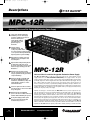
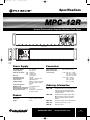
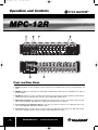
MPC12R.qxd
7/7/06
10:46 AM
Page 1
MPC-12R
Universal Chassis and Hot-Swappable Redundant Power Supply
Installation and
Operation Manual
Ph:800-421-6511
www.picomacom.com
Operation
Manual
Rev. 07/06
MPC12R.qxd
7/7/06
10:46 AM
Page 2
Safeguards
MPC-12R
Product Inspection
Inspect the equipment for shipping damage. Should any damage be discovered, immediately file a claim with the carrier.
Important Safety Instructions
To insure proper installation and operation, take a moment to read this guide before proceeding with the installation. If you have any questions
or comments about the MPC-12R universal chassis, please contact your dealer or have him contact the PICO MACOM Service Center at this
phone number: 800-421-6511.
The lightning flash with arrowhead symbol, within an
equilateral triangle, is intended to alert the user to the
presence of un-insulated “dangerous voltage” within the
product's enclosure that may be of sufficient magnitude
to constitute a risk of electric shock to persons.
The exclamation point within an equilateral triangle is
intended to alert the user to the presence of important
operating and maintenance (servicing) instructions in
the literature accompanying the appliance.
WARNING:
TO REDUCE THE RISK OF FIRE OR ELECTRIC SHOCK, DO NOT EXPOSE THIS APPLIANCE
TO RAIN OR MOISTURE. DO NOT OPEN THE CABINET.
REFER SERVICING TO QUALIFIED PERSONNEL ONLY.
CAUTION:
TO PREVENT ELECTRIC SHOCK DO NOT USE THIS (POLARIZED) PLUG WITH AN EXTENSION
CORD RECEPTACLE OR OTHER OUTLET UNLESS THE BLADES CAN BE FULLY INSERTED
TO PREVENT BLADE EXPOSURE.
ATTENCION:
POUR PREVENIR LES CHOCS ELECTRIQUES, NE PAS UTILISER CETTE FICHE POLARISEE AVEC
UN PROLONGATEUR, UNE PRISE DE COURANT OU UNE AUTRE SORTIE DE COURANT, SAUF SI
LES LAMES PEUVENT ETRE INSEREES A FOND SANS EN LAISSER AUCUNE PARTIE A DECOUVERT.
1. Read Instructions: All safety and operating instructions should
be read before the appliance is operated.
2. Retain Instructions: The safety and operating instructions
should be retained for future reference.
3. Heed Warnings: All warnings on the appliance should be
adhered to.
4. Follow Instructions: All operating and user instructions should
be followed.
5. Cleaning: Unplug this appliance from the wall outlet before cleaning. Use a damp cloth for cleaning. Do not use liquid cleaners or
aerosol cleansers.
6. Do Not Use Attachments: Use of attachments not recommended
by the manufacturer may cause hazards.
7. Water and Moisture: Do not use this product near water—for
example, near a bathtub, washbowl, kitchen sink, laundry tub, in a
wet basement, or near a swimming pool—and the like.
2
Rev. 07/06
Ph:800-421-6511
8. Accessories: Do not place this product on an unstable cart,
stand, tripod, bracket, or table. The product may fall, causing serious
injury to a child or adult, and serious damage to the appliance.
9. Ventilation: This video product should never be placed near or
over a radiator or heat register. This video product should not be
placed in a built-in installation such as a bookcase or rack unless
proper ventilation is provided or the manufacturer’s instructions have
been adhered to. Any slots or opening in the cabinet are provided for
ventilation. To ensure reliable operation of the video product and to
protect it from overheating, these openings must not be blocked or
covered. Openings should never be blocked by placing the product
on a bed, sofa, rug, or other similar surface.
10. Grounding or Polarization: This video product is equipped with
either a three prong plug for 110 VAC use or a two prong flat blade
220 volt type plug. Each type is to be inserted into only the type of
receptacle for which they specifically designed. Do not cut off the
round grounding pin in order to be able to fit into a two prong receptacle as this could cause injury and will void the warranty.
www.picomacom.com
MPC12R.qxd
7/7/06
10:46 AM
Page 3
Safeguards
MPC-12R
11. Power Sources: This product should be operated only from the
type of power source indicated on the marking label. If you are not
sure of the type of power supplied to your home, consult your appliance dealer or local power company.
12. Power-cord Protection: Power-supply cords should be routed
so they are not likely to be walked on or pinched by items placed
upon or against them. Pay particular attention to cords and plugs,
convenience receptacles, and the point where they exit from the
appliance.
13. Lightning: For added protection for this product during a lightning
storm, or when it is left unattended or unused for long periods of time,
the unit should be disconnected from power source.
14. Power Lines: An outside antenna system should not be located
in the vicinity of overhead power lines, other electric light or power circuits, where it can fall into such power lines or circuits. When
installing an outside antenna system, extreme care should be taken
to keep from touching such power lines or circuits as contact with
them may be fatal.
15. Overloading: Do not overload wall outlets and extension cords
as this can result in risk of fire or electric shock.
16. Object and Liquid Entry: Never push objects of any kind into this
product through openings as they may touch dangerous voltage
points or short-out parts that could result in a fire or electric shock.
Never spill liquid of any kind on the product.
17. Servicing: Do not attempt to service this product yourself as
opening or removing covers may expose you to dangerous voltage or
other hazards. Refer all servicing to qualified service personnel.
18. Damage Requiring Service: Unplug this product from the wall
outlet and refer servicing to qualified service personnel under the following conditions:
a. When the power-supply cord or plug is damaged.
b. If liquid has been spilled, or objects have fallen into the product.
product, be sure the antenna or cable system is grounded so as to
provide some protection against voltage surges and built-up static
charges.
a. Use No.10 AWG (5.3mm) copper, No.8 AWG (8.4mm) aluminum, No.7 AWG (10mm) copper-clad steel or bronze wire or
larger, as ground wire.
b. Secure antenna lead-in and ground wires to house with standoff insulators spaced from 4 feet (1.22m) to 6 feet (1.83m) apart.
c. If the product has been exposed to rain or water.
d. If the product does not operate normally by following the operating instruction. Adjust only those controls that are covered by
the operating instructions. An improper adjustment may result in
damage and will often require extensive work by a qualified technician to restore the product to its normal operation.
e. If the product has been dropped or the cabinet has been
damaged.
f. When the product exhibits a distinct change in performance—
this indicates a need for service.
19. Replacement Parts: When replacement parts are required, be
sure the service technician has used replacement parts specified by
the manufacturer or have the same characteristics as the original
parts. Unauthorized substitutes may result in fire, electric shock or
other hazards.
20. Safety Check: Upon completion of any service or repairs to this
product, ask the service technician to perform safety checks to determine that the product is in proper operating conditions.
c. Mount antenna discharge unit as close as possible to where
lead-in enters house.
d. A driven rod may be used as the grounding electrode where
other types of electrode systems do not exist. Refer to the
National Electrical Code, ANSI/NFPA 70-1984 for information.
e. Use jumper wire not smaller than No.6 AWG (13.3mm) copper
or equivalent, when a separate antenna grounding electrode is
used.
NOTE TO THE CATV SYSTEM INSTALLER
THIS REMINDER IS PROVIDED TO CALL THE CATV SYSTEM
INSTALLER’S ATTENTION TO ARTICLE 820-22 OF THE NEC
THAT PROVIDES GUIDELINES FOR PROPER GROUNDING
AND, IN PARTICULAR, SPECIFIES THAT THE CABLE GROUND
SHALL BE CONNECTED TO THE GROUNDING SYSTEM OF
THE BUILDING, AS CLOSE TO THE POINT OF CABLE ENTRY
AS PRACTICAL.
21. Outdoor Antenna Grounding: Before attempting to install this
Ph:800-421-6511
www.picomacom.com
3
Rev. 07/06
MPC12R.qxd
7/7/06
10:46 AM
Page 4
Descriptions
MPC-12R
Universal Chassis and Hot-Swappable Redundant Power Supply
State-of-the-Art full module N+1
redundancy ensures dual supply
operation enabling hot insertion or
removal of either power
supply module without
system disruption and
guaranteeing zero
down time
Current sharing,
redundant design, and
cooling fan provides much
less current load per supply ensuring
cooler operation thereby substantially
improving their long-term reliability
High efficiency supplies (over 75%)
minimize power consumption and
heat dissipation
High isolation O Ring blocking diodes
provide unit-to-unit short circuit
protection and isolation from hot-swap
interaction by preventing power bus
disturbance
Internal fusing circuitry provides
current overload protection and precise
voltage regulation thereby preventing
component damage
Universal and fully compatible with
Pico Macom SAW filtered plug-in
modulators, demodulators, and power
supply modules, and those of most
other manufacturers
Precision engineered chassis enables
smooth insertion or removal of modules
along slide guides
Dedicated home-run individual
power connections facilitate removal of
modules without disabling the system
Front panel display provides quick
and easy system monitoring and
troubleshooting reference
4
Rev. 07/06
MPC-12R
Universal Chassis and Hot-Swappable Redundant Power Supply
Pico Macom’s MPC-12R is a 2RU (31/2˝ high) state-of-the-art 19˝ rack-mountable chassis
equipped with fan-cooled HOT-SWAPPABLE REDUNDANT power supply modules. The power
supply system (4-module wide) consists of a pair of ultra compact 78-Watt multiple output modules
specifically designed for mini-mod applications that require ultra-reliable DC input supply. The supplies combine advanced forward converter topology and extensive surface mount technology to
achieve excellent power density. Sophisticated packaging and filtering techniques minimize overall system filtering. Current sharing and redundant supply design, equally shares loads between the
supplies and minimize the potential for power bus glitches after a power supply has failed, thereby
improving the longevity of the power supply.
Capable of housing up to 12 mini modules, the MPC-12R chassis is precision engineered to provide smooth insertion and removal of modules within the provided slide guides. The unit employs a
universal wire-harness configuration that can accommodate mini modules from Pico Macom,
including agile modulators and demodulators, and those from many other manufacturers in a mix
and match fashion. Installation is easy. Just slide the modulator or demodulator into the racking system and plug in the supplied power supply cable and connector. Precise and automated manufacturing and value engineering ensure unmatched quality, timely delivery and very competitive cost.
Custom assembled and fully tested multi-channel systems are also available from Pico Macom
with the combination of fixed channel and/or agile mini-modulators and demodulators to meet your
requirements. Pico Macom backs up this product with its industry leading 5-year limited warranty.
Ph:800-421-6511
www.picomacom.com
MPC12R.qxd
7/7/06
10:46 AM
Page 5
Specifications
MPC-12R
Universal Chassis and Hot-Swappable Redundant Power Supply
®
MPC-HSS
®
MPC-HSS
Front View
MPC-BP
Cover
Plate
Rear View
Power Supply
Connectors
90 to 264 VAC
47 to 63 Hz
V1: 5 VDC/4 A
V2: 12 VDC/3.5 A
V3: 30 VDC/.27 A
Efficiency:
>75% typical
Operating Frequency:
100 kHz
Input Inrush Current:
<30 A @ 115 VAC @ 25° C
Line Protection:
PCB AC line fuse
DC Output Ripple:
Within 1% (Vpp) at maximum
load @ 25° C @ PS output
terminal
Line/Load Regulation:
±1%
Minimum Load:
10% of full rated load
Operating Temperature Range: 0° to 60° C
Storage Temperature Range: -40° to 85° C
Overcurrent Protection:
No damage to outputs when
shorted to ground
Input (on back plane):
Output (on back plane/
each connector):
Input Voltage Range:
Frequency Range:
Output Specifications:
Chassis
Dimensions:
Weight:
19˝(L) x 71/2˝(D) x 31/2˝(H)
7.8 lbs.
IEC 320 inlet connector
12 Pin: Pins
Pins
Pins
Pins
4 Pin: Pins
Pins
Pins
Pins
1,5,9 - 5 VDC
2,6,10 - 12 VDC
3,7,11 - Ground
4,8,12 - 30 VDC
1 - 5 VDC
2 - 12 VDC
3 - Ground
4 - 30 VDC
Ordering Information
MPC-12R
12-Mini-Mod Chassis and Redundant Power
Supply System Chassis Equipped with
2-Hot-Swap Modules, Backplane-Bracket,
and Wire Harness
MPC-HSR
Redundant Power Supply Upgrade Kit for
MPC12 System Consists of 2-Hot-Swap
Modules, Backplane-Bracket, and Wire
Harness
MPC-HSS
Replacement Single Power Supply Module
MPC-12C
Universal Chassis (chassis only)
MPC-BP
Blank Cover Plate
Ph:800-421-6511
www.picomacom.com
5
Rev. 07/06
MPC12R.qxd
7/7/06
10:46 AM
Page 6
Operation and Controls
MPC-12R
Front and Rear Views
1. MPCD: Demodulator accepts any NTSC television signal from 54 to 806 MHz and converts it to baseband video and
audio.
2. MPCMA: Modulators are fully agile from 54-860 MHz, including HRC and IRC offsets. The MPCMA is also adjacent
channel capable.
3. MPCM45: Modulators are factory re-tunable within band. They provide adjacent channel capability for VHF channels
2-ZZZ, UHF channels 14-69 and cable channels 2-125, including HRC and IRC offsets.
4. MPC-HSS Power Supply: Hot swappable redundant power supply supplies, provides +12 Vdc and +5 Vdc to the modulators and demodulators. MPC-HSR power supply input will operate from 90 to 264 Vac.
5. Power Supply Power Distribution Bracket: This device provides the interface for the MPC-HSS power supplies and the MPCM45, MPCMA and MPCD modules.
6
6
Rev. 07/06
Power Cables: Easily removable cables provide DC voltage from MPC-HSR power supply to the MPC-12R modules.
"Home-run" configuration allows removal of modules without disabling entire system.
Ph:800-421-6511
www.picomacom.com
MPC12R.qxd
7/7/06
10:46 AM
Page 7
Installation Procedure
MPC-12R
Installation
It is recommended that assistance be available to safely install equipment
in equipment racks. Chassis must be fastened securely in equipment rack
before populating with modules.
1.
Install chassis in equipment rack (equipment rack sold separately) by supporting the bottom and rear of chassis at the desired elevation in rack.
2.
Line up the side holes of chassis with the tapped equipment rack holes
3.
Insert the provided screws through the side holes in chassis and thread
into the tapped equipment rack holes.
4.
Fasten the bottom screws first, then fasten top screws, tighten securely.
5.
Slide power supply and equipment modules into chassis.
6.
Connect power supply to all modules before supplying line power to the
power supply.
7.
Connect modules as described in the manual associated with module.
OPERATION AND CARE
Do’s & Don’ts
•
•
•
•
•
•
Always operate in a cool well ventilated environment.
Always provide a stable, conditioned power source.
Heed all safety warnings and obey all environmental and electrical
operating requirements.
To clean, use a damp cloth only and clean only with mild soap.
Do not use solvents or harsh detergents.
Do not use this product for purposes other than intended.
HEADEND/DISTRIBUTION INTERFACE
MODULE REPLACEMENT
1. Power Supply:
• Remove power supply by sliding the unit out the front of
the chassis.
• Insert replacement power supply into chassis.
2. Modules:
• Disconnect the 3 pin molex connector from module.
• Disconnect the audio, video, and RF connectors from back of
module.
• Remove module by sliding the unit out the front of the chassis.
• Insert replacement module into chassis.
• Reconnect the 3 pin molex connector and audio, video, and RF
connectors to the rear of module.
PICO MACOM recommends connecting the headend components
in the following manner:
Each of the modulators, signal processors or strip amplifiers output
are connected to a combining network. Either a PHC-12G or a PHC24G headend combiner may be used to accomplish this purpose.
The PHC-12G or PHC-24G passive headend combiner consists of
two rows of directional couplers combined by a hybrid splitter. Normally,
the odd channels are combined on one row while even channels are
combined on the other row of directional couplers for maximum isolation. The output of the combiners may be connected to the input of a
launch amplifier such as a CA-30RK550 or CA-30RK1000. The output
of the amplifier is connected to the main distribution line.
A 24 channel system hook-up is shown. (The same combining result
may be accomplished by using a single PHC-24G). The two
PHC-12G outputs are combined via a two-way splitter, which is connected to a CA-30RK1000 launch amplifier. The input levels to the
combiner, whether from a modulator, signal processor or a strip amplifier, must be at the same amplitude.
Ph:800-421-6511
www.picomacom.com
7
Rev. 07/06
MPC12R.qxd
7/7/06
10:46 AM
Page 8
Warranty
MPC-12R
Five Year Limited Warranty*
Pico Macom, Inc. warrants to the original purchaser this product shall be free of defects in material and craftsmanship with only the
limitations or exclusions set out below.
During the warranty period, Pico Macom, Inc. or an authorized Pico Macom service facility will provide, free of charge, the parts and
labor necessary to correct defects in material and workmanship.
Warranty Duration
1.
2.
3.
4.
This warranty shall terminate five years* from the original date of purchase of the product or at a time the product is:
Misused or damaged due to neglect or improper installation.
Modified.
Repaired by someone other than the warrantor.
Sold by the original purchaser.
Statement of Remedy
To obtain such a warranty service, contact the salesperson where the product was obtained. You will be issued a Return Authorization
(RA) number, which will be used to track your product. Be prepared to provide:
1. The model number and channel number of the product.
2. The date of purchase.
3. A specific identification of the problem.
Deliver the products to Pico Macom, Inc. or ship the products in the original packing material at the address at the bottom of the page.
Include satisfactory evidence of the date of purchase.
Products will not be accepted by Pico Macom, Inc. without the RA number clearly indicated on the shipping label.
The foregoing constitutes the Pico Macom, Inc. entire obligation with respect to this product and the original purchaser and any
user or owner shall have no other remedy and no claim for incidental or consequential damages. Some states do not allow
limitations on how long an implied warranty lasts or do not allow the exclusions or limitation of incidental or consequential
damages, so the above limitation and exclusion may or may not apply to you.
This warranty gives you specific legal rights, and you also have rights, that vary from state to state. (U.S.A.)
* One year warranty if sold outside U.S.A.
Pico Macom, Inc.
6260 Sequence Drive
San Diego, CA 92121
8
Rev. 07/06
Ph:800-421-6511
www.picomacom.com