1
Operating Instructions
Multi-format Live Switcher
Model No.
AV-HS300G
Before operating this product, please read the instructions carefully and save this manual for
future use.
Safety precautions
FCC Note:
This equipment has been tested and found
to comply with the limits for a class A digital
device, pursuant to Part 15 of the FCC Rules.
These limits are designed to provide reasonable
protection against harmful interference when
the equipment is operated in a commercial
environment. This equipment generates, uses,
and can radiate radio frequency energy, and
if not installed and used in accordance with
the instruction manual, may cause harmful
interference to radio communications. Operation
of this equipment in a residential area is likely to
cause harmful interference in which case the user
will be required to correct the interference at his
own expense.
CAUTION
RISK OF ELECTRIC SHOCK
DO NOT OPEN
CAUTION: TO REDUCE THE RISK OF ELECTRIC SHOCK,
DO NOT REMOVE COVER (OR BACK).
NO USER SERVICEABLE PARTS INSIDE.
REFER TO SERVICING TO QUALIFIED SERVICE PERSONNEL.
The lightning flash with arrowhead
symbol, within an equilateral triangle, is
intended to alert the user to the presence
of uninsulated “dangerous voltage” within
the product’s enclosure that may be of
sufficient magnitude to constitute a risk of
electric shock to persons.
The exclamation point within an equilateral
triangle is intended to alert the user to
the presence of important operating and
maintenance (service) instructions in the
literature accompanying the appliance.
Warning:
To assure continued FCC emission limit
compliance, the user must use only shielded
interface cables when connecting to external units.
Also, any unauthorized changes or modifications
to this equipment could void the user’s authority to
operate it.
For CANADA
This class A digital apparatus complies
with Canadian ICES-003.
Cet appareil numérique de la classe A
est conforme à la norme NMB-003 du
Canada.
CAUTION:
In order to maintain adequate ventilation, do
not install or place this unit in a bookcase,
built-in cabinet or any other confined space.
To prevent risk of electric shock or fire hazard
due to overheating, ensure that curtains
and any other materials do not obstruct the
ventilation.
WARNING:
•TO REDUCE THE RISK OF FIRE OR
ELECTRIC SHOCK, DO NOT EXPOSE THIS
APPARATUS TO RAIN OR MOISTURE.
•THE APPARATUS SHALL NOT BE EXPOSED
TO DRIPPING OR SPLASHING AND THAT
NO OBJECTS FILLED WITH LIQUIDS, SUCH
AS VASES, SHALL BE PLACED ON THE
APPARATUS.
Note:
The rating plate (serial number plate) is on
the bottom of the unit.
The socket outlet shall be installed near the
equipment and easily accessible or the mains
plug or an appliance coupler shall remain readily
operable.
WARNING:
TO PREVENT INJURY, THIS APPARATUS
MUST BE SECURELY ATTACHED TO THE
FLOOR/WALL IN ACCORDANCE WITH THE
INSTALLATION INSTRUCTIONS.
A warning that an apparatus with CLASS I
construction shall be connected to a MAINS
socket outlet with a protective earthing connection.
CAUTION:
TO REDUCE THE RISK OF FIRE OR SHOCK
HAZARD AND ANNOYING INTERFERENCE,
USE THE RECOMMENDED ACCESSORIES
ONLY.
indicates safety information.
Safety precautions
IMPORTANT SAFETY INSTRUCTIONS
Read these operating instructions carefully before using the unit. Follow the safety instructions on the
unit and the applicable safety instructions listed below. Keep these operating instructions handy for future
reference.
1) Read these instructions.
10)Protect the power cord form being walked on or
pinched particularly at plugs, convenience
receptacles, and the point where they exit from
the apparatus.
2) Keep these instructions.
3) Heed all warnings.
11)Only use attachments/accessories specified by
the manufacturer.
4) Follow all instructions.
5) Do not use this apparatus near water.
12)Use only with the cart, stand,
tripod, bracket, or table specified
by the manufacturer, or sold with
the apparatus. When a cart is
used, use caution when moving
the cart/apparatus combination to
avoid injury from tip-over.
6) Clean only with dry cloth.
7)Do not block any ventilation openings. Install
in accordance with the manufacturer's
instructions.
8)D o not install near any heat sources
such as radiators, heat registers, stoves, or
other apparatus (including amplifiers) that
produce heat.
13)Unplug this apparatus during lightning storms
or when unused for long periods of time.
14)R efer all servicing to qualified service
personnel. Servicing is required when the
apparatus has been damaged in any way, such
as power-supply cord or plug is damaged,
liquid has been spilled or objects have fallen
into the apparatus, the apparatus has been
exposed to rain or moisture, does not operate
normally, or has been dropped.
9)D o not defeat the safety purpose of the
polarized or grounding-type plug. A polarized
plug has two blades with one wider than the
other. A grounding-type plug has two blades
and a third grounding prong. The wide blade or
the third prong are provided for your safety. If
the provided plug does not fit into your outlet,
consult an electrician for replacement of the
obsolete outlet.
indicates safety information.
Safety precautions
Information on Disposal for Users of Waste Electrical & Electronic Equipment
(private households)
This symbol on the products and/or accompanying documents means that used electrical and
electronic products should not be mixed with general household waste.
For proper treatment, recovery and recycling, please take these products to designated
collection points, where they will be accepted on a free of charge basis. Alternatively, in some
countries you may be able to return your products to your local retailer upon the purchase of an
equivalent new product.
Disposing of this product correctly will help to save valuable resources and prevent any potential negative
effects on human health and the environment which could otherwise arise from inappropriate waste handling.
Please contact your local authority for further details of your nearest designated collection point.
Penalties may be applicable for incorrect disposal of this waste, in accordance with national legislation.
For business users in the European Union
If you wish to discard electrical and electronic equipment, please contact your dealer or supplier for further
information.
Information on Disposal in other Countries outside the European Union
This symbol is only valid in the European Union.
If you wish to discard this product, please contact your local authorities or dealer and ask for the correct
method of disposal.
Contents
Description . ............................................. 6
3. Setup . ................................................. 28
Features ................................................... 6
3-1 Setting the input signals ...............................
3-1-1 Setting the input signals (IN 1 to 5) ........
3-1-2 Setting the input signal frame
synchronizer .........................................
3-1-3 Setting the DVI input signals (IN6) .........
Precautions for use ................................. 7
1. Functions in each area . ...................... 8
28
28
28
29
1-2 Crosspoint area . ............................................ 9
3-2 Setting the output signals . ........................... 31
3-2-1 Types of output signals ........................... 31
3-2-2 Selecting the AUX signals ...................... 31
1-3
Wipe area . ................................................... 10
3-3
1-4
Transition area . ............................................ 11
1-5
LCD menu area . .......................................... 12
3-4 Setting the crosspoints . ............................... 33
3-4-1 Assigning signals to the crosspoints ...... 33
3-4-2 Setting the crosspoint switching ............. 34
1-6
Rear panel connections area ....................... 13
3-5
Setting the sync signals ............................... 35
2. Basic operations . .............................. 14
3-6
Adjusting the output signal phase ................ 36
3-7
Network settings .......................................... 38
1-1
Control panel . ................................................ 8
2-1 Transitions ....................................................
2-1-1 Selecting the bus ....................................
2-1-2 Selecting the bus mode ..........................
2-1-3 Selecting the transition mode .................
2-1-4 Manual transition
(using the fader lever) ..........................
2-1-5 Auto transition . .......................................
14
14
14
15
2-2 Wipe .............................................................
2-2-1 Selecting the wipe pattern ......................
2-2-2 Selecting the wipe direction . ..................
2-2-3 Wipe decorations
(border, soft effect) . ..............................
16
16
16
2-3 Key ...............................................................
2-3-1 Selecting the key source ........................
2-3-2 Setting the key . ......................................
2-3-3 Key adjustments .....................................
2-3-4 Selecting key fill ......................................
2-3-5 Key decorations ......................................
18
18
19
19
20
21
3-8 Other settings . .............................................
3-8-1 LCD backlight .........................................
3-8-2 Setting the ancillary data ........................
3-8-3 BB signal setup level ..............................
15
15
3-9
Color background ......................................... 23
2-5
Freezing the input signals ............................ 24
2-6
Frame memory ............................................. 25
2-7
Preset memory . ........................................... 26
40
40
40
40
Status displays ............................................. 41
3-10 Initialization .................................................. 41
4. Setting menu table ............................ 42
16
2-4
Selecting the video format ........................... 32
5. Image transmission functions . ........ 47
6. External interfaces ............................ 51
6-1
RS-422 connector ........................................ 51
6-2 GPI connector .............................................. 51
6-3
Tally connector ............................................. 52
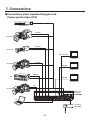
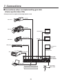
7. Connections ....................................... 53
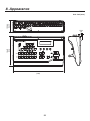
8. Appearance ........................................ 55
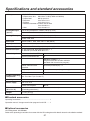
Specifications and
standard accessories . .......................... 56
Appendix (glossary) .............................. 58
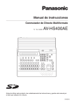
Description
This unit is a 1ME digital video switcher which supports multiple HD and SD formats. While featuring compact
dimensions, it can optionally support HD analog component inputs (5) in addition to the five SDI inputs and one
DVI-I input. Since a frame synchronizer is incorporated for each of the inputs, asynchronous video signals can be
switched without “shocking” or “freezing”. Furthermore, the images created by a PC can be captured via Ethernet.
Features
Six inputs, three outputs supported despite its compact size
The standard configuration consists of six inputs (five SDI inputs and one DVI-I input) and three outputs of
PGM, PVW and AUX (SDI, HD analog component). Optionally, the unit is also capable of supporting HD analog
component inputs (5).
The SDI inputs support active through outputs. Key inputs can be selected from the six video inputs for use.
Multiple formats supported
HD formats (1080/59.94i, 1080/50i, 720/59.94p and 720/50p), SD formats (480/59.94i and 576/50i) and DVI-I
(input only) are supported as the signal formats.
Frame synchronizer system as well as external sync system is supported
The unit contains a high-performance 10-bit frame synchronizer to enable asynchronous images to be input.
By using the BB (Black Burst) signal output, a system can be configured using the switcher’s sync signals as a
reference.
Gen‑lock is also possible with external sync signals (BB or Tri-level Sync).
Built-in effects and key combination functions
The unit provides nine different wipe patterns to add borders or soft effects.
Key combination supports self keys and linear keys, and key invert is also possible.
Ethernet and control interfaces supported
The unit can capture images created on a PC into its frame memory over Ethernet (100 Mbps or 10 Mbps) and
use them as background images or key input signals.
External control using RS-422 or GPI signals is also supported. In addition, the unit comes with six tally
outputs.
External power supply system
The unit is powered by an external DC 12 V power supply so it can be used not only indoors but in the field as
well. (However, the unit is not constructed to be rain-proof or drip-proof so keep it away from rain or moisture.)
Easy operability
The simple panel layout which enables the functions to be operated directly enables speedy live transmissions.
Preset-like operations can be performed using a menu-driven format.
Precautions for use
Handle carefully.
Do not drop the product, or subject it to strong shock or vibration.
Do not carry or move the product by the fader lever. This is important to prevent trouble.
Use the product in an ambient temperature of 32 °F to 104 °F (0 °C to 40 °C).
Avoid using the product at a cold place below 32 °F (0 °C) or at a hot place above 104 °F (40 °C) because
extremely low or high temperature will adversely affect the parts inside.
Power off before connecting or disconnecting cables.
Before plugging or unplugging the cables, be sure to switch power off.
Avoid humidity and dust.
Avoid using the product at a humid, dusty place because much humidity and dust will cause damage to the
parts inside.
Maintenance
Wipe the product using a dry cloth. To remove stubborn dirt, dip a cloth into a diluted solution of kitchen
detergent, wring it out well, and wipe the product gently. Then, after wiping the product with a moist cloth, wipe
it again with a dry cloth.
Caution
• Avoid using benzine, paint thinners and other volatile fluids.
• If a chemical cleaning cloth is to be used, carefully read through the precautions for its use.
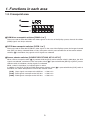
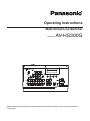
1. Functions in each area
1-1. Control panel
Power indicator [POWER]
This lights when the power switch (2) is set to ON while power is supplied to the DC power socket.
It goes off when the power switch (2) is set to OFF.
Power switch
When this switch is set to “ I ” while power is supplied to the DC power socket, the unit’s power is turned
on, and the power indicator (1) lights. When it is set to “O”, the unit’s power is turned off, and the power
indicator (1) goes off.
Alarm indicator [ALARM]
This lights when the fan has stopped running or when something is wrong with the DC power (such as a drop
in voltage). When the alarm goes off you can check the type of problem with the ALM item under the SETUP/
STATS (15/15) menu. An alarm message will also appear on the LCD.
ALARM TYPE
Fan alarm
Power alarm
Power alarm and fan alarm
SETUP/STATS (15/15) ALM
FAN
POWR
F, P
ALARM MESSAGE
ALARM! FAN STOP
ALARM! POWER DOWN
ALARM! POWER DOWN & FAN STOP
If the fan alarm goes off, stop using the unit immediately and be sure to contact your dealer. If the power alarm
goes off, stop using the unit immediately and check the power. Continuing to use the unit even after the alarm
goes off could damage it.
If the temperature inside the unit increases due to the fan stopping or some other reason, the safety function
will activate and the power of the unit will be turned off.
1. Functions in each area
1-2. Crosspoint area
PGM/A bus crosspoint switches [PGM/A 1 to 7]
These are used to select the PGM/A bus video signals. In the case of the flip-flop system, the main line video
(PGM) signals are always selected.
PST/B bus crosspoint switches [PST/B 1 to 7]
These are used to select the PST/B bus video signals. In the case of the flip-flop system, the images inserted
next (PST) are always selected. When a B bus crosspoint switch is pressed while one of the source selector
switches (6) is held down, key signals or AUX signals are selected.
Source selector switches [SOURCE SELECT/AUX, KEY-S, KEY-F]
When a B bus crosspoint switch (5) is pressed while the [AUX] source selector switch is held down, the AUX
signals are selected, and when a B bus crosspoint switch (5) is pressed while the [KEY-S] or [KEY-F] source
selector switch is held down, the key signals are selected.
While a switch is held down, its indicator lights in amber.
In addition, if the [CLN], [PVW] or [PGM] wipe pattern selector switch (7) is pressed while the [AUX] switch is
held down, the switch will operate as an AUX bus selector switch.
[CLN]: Clean signals are output to the AUX bus. See 3-2-2
[PVW]: PVW signals are output to the AUX bus. See 3-2-2
[PGM]: PGM signals are output to the AUX bus. See 3-2-2
1. Functions in each area
1-3. Wipe area
Wipe pattern selector switches [WIPE PATTERN / FUNC]
These are used to select the wipe patterns. Each switch is used to select
one of the nine wipe patterns.
The indicator of the switch for the selected pattern lights (in amber).
When the [FUNC] switch (9) has been pressed and its indicator is lighted,
the function setting menu is selected, and the indicator lights up green.
Wipe direction selector switch [N N/R R]
This is used to select the wipe direction. See 2-2-2
[N]:
For setting the wipe direction to the normal direction.
[N/R]:To switch the wipe direction between normal and reverse when the execution of the transition has
been completed.
[R]:
For setting the wipe direction to the reverse direction.
[FUNC] switch
When this switch is pressed, its indicator lights up green. If a wipe pattern selector switch is pressed while
its indicator is lighted, the wipe pattern selector switch lights up green, and the setting menu of the function
indicated underneath the switch appears on the LCD display.
[TIME]:
For setting the auto transition time.
See 2-1-5
[WIPE]:
For setting the wipe border and soft effect.
See 2-2-3
[CBGD]: For setting the color background.
See 2-4
[KEY]:
See 2-3
For setting the key.
[EDGE]: For setting the key edge.
See 2-3-5
[FRZ]:
For displaying the freeze status display and setting freezing. See 2-5
[MEM]:
For setting the preset memory or frame memory.
See 2-6, 2-7
[XPT]:
For displaying and setting the crosspoint assignment.
See 3-4
[SETUP]: For performing the system settings.
See 3
Freeze status indicator LED
When this LED is lighted, it means that one of the input signals is frozen.
When the [FUNC] switch (9) is pressed and its indicator is lighted and then the [FRZ] switch is pressed, the
freeze status is indicated for each input. (An asterisk ( ) appears above the name of a frozen crosspoint.)
Bear in mind that since the signals are frozen while the indicator is lighted, the unit’s output will remain
unchanged even if the input images change.
(When crosspoints 3 and 5 are frozen)
'3;
'3;
915
10
1. Functions in each area
1-4. Transition area
[BKGD] switch
This executes the background transition when the [AUTO] switch () or fader
lever () has been operated.
When the [BKGD] switch is pressed and it is selected, its indicator is lighted in
amber. If the [KEY] switch () is now pressed, the indicator goes off, and the
de‑selected status is established.
When the [BKGD] switch and [KEY] switch () are pressed at the same time, both
switches are set to the selected status.
The selection status cannot be changed while a transition is being executed or
suspended.
[KEY] switch
This executes the key transition (MIX) when the [AUTO] switch () or fader lever () has been operated.
When the [KEY] switch is pressed and it is selected, its indicator lights in amber.
If the [BKGD] switch () is now pressed, the indicator goes off, and the de-selected status is established.
When the [BKGD] switch () and [KEY] switch are pressed at the same time, both switches are set to the
selected status.
The selection status cannot be changed while a transition is being executed or suspended.
KEY ON tally LED
This lights in red when the key ON status is established.
[MIX] switch
This is used to switch the A and B bus images while making them overlap.
During the transition, the A and B bus output total is kept at 100 %.
When the [MIX] switch is pressed and it is selected, its indicator lights in amber.
If the [WIPE] switch () is now pressed, it goes off, and the de-selected status is established.
[WIPE] switch
This is used to execute the transition using the pattern selected by the wipe pattern selector switch ().
When the [WIPE] switch is pressed and it is selected, its indicator lights in amber.
If the [MIX] switch () is now pressed, it goes off, and the de-selected status is established.
[AUTO] switch
This is used to automatically execute transitions (auto transition) using the transition time which has been set.
During auto transition its indicator lights in red. When the switch is pressed again during auto transition, the
auto transition operation is suspended, and the indicator lights in green. When it is pressed again while auto
transition is suspended, the remaining transition is executed.
The indicator goes off when auto transition is completed.
When the [AUTO] switch is pressed while the fader lever () is at an interim position, the remaining transition
is executed using the transition time which has been set.
11
1. Functions in each area
Fader lever
This is used to execute background or key transitions. When it is moved as far as it will go, the transition
is completed. When it has been operated during auto transition, auto transition will be switched to manual
operation as soon as the fader position overtakes the amount of the transition being executed.
Bus tally LEDs
These indicate the output statuses of the A bus and B bus. The LED corresponding to the bus whose program
signals (PGM) are being output lights.
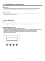
1-5. LCD menu area
LCD
The setting menus are displayed on the LCD.
When the [FUNC] switch (9) is pressed and its indicator is lighted and then one of the wipe pattern selector
switches (7) is pressed, the setting menu for the function concerned is displayed.
Rotary encoders [F1] to [F4]
These are used to set the parameters displayed on the menu.
Menu items are selected and parameters set by rotating [F1] to [F4]. This operation is effective only when the
[FUNC] switch is lighting. For details on their operation, refer to the items in “2. Basic operations”.
When the [F1] to [F4] switches are held down, the parameters are returned to their default status.
(Numerical value setting items only)
(Startup screen)
<AV-HS300>
VER1.00
12
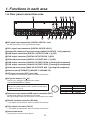
1. Functions in each area
1-6. Rear panel connections area
SDI signal input connectors [DIGITAL INPUTS 1 to 5]
IN: SDI signal input; OUT: active through output
DVI-I signal input connector [DIGITAL INPUTS 6 DVI-I]
Analog HD component input connectors [ANALOG INPUTS 1 to 5] (optional)
PGM output connectors [DIGITAL OUTPUTS PGM 1, 2] (SDI)
PVW output connector [DIGITAL OUTPUTS PVW 1] (SDI)
AUX output connectors [DIGITAL OUTPUTS AUX 1, 2] (SDI)
PGM output connector [ANALOG OUTPUTS PGM 1] (analog HD component)
PVW output connector [ANALOG OUTPUTS PVW 1] (analog HD component)
AUX output connector [ANALOG OUTPUTS AUX 1] (analog HD component)
Ethernet port [ETHERNET] (10BASE-T, 100BASE-TX)
GPI input connector [GPI] (auto take)
For details on connection, refer to “6. External interfaces”.
DC power socket [12V IN]
The DC 12 V voltage is supplied to this socket.
Use the AW-PS505A AC adaptor.
Note
When using other power sources, make sure the output
is DC 12 V 2 V, 5 A.
Reference input connector/BB output connector [REF]
Loop-through output in the external sync mode.
BB signals output from both connectors in the internal sync mode.
RS-422 interface connector [RS-422]
For details on connection, refer to “6. External interfaces”.
Tally output connector [TALLY]
For details on connection, refer to “6. External interfaces”.
Ground connector
Connect to the system’s earth ground.
13
Pin No.
1
2
3
4
Signal name
GND
NC
NC
DC12V
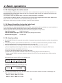
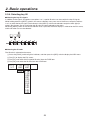
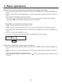
2. Basic operations
2-1. Transitions
2-1-1. Selecting the bus
Press the crosspoint switches to select the material which will be targeted for the background transition.
By pressing these switches, the signals are selected, and the indicators of the selected switches light.
The color in which the switch indicators light differs depending on the operation status.
Lighting in red:
When the selected input signals are output to PGM.
Lighting in green: When the selected input signals are not output to PGM.
Lighting in red
Lighting in green
For details on how to select the key source bus and key fill bus, refer to “2-3-1” and “2-3-4”.
For details on how to select the AUX bus, refer to “3-2-2”.
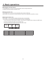
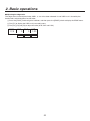
2-1-2. Selecting the bus mode
Select the A/B bus system or flip-flop system (PGM/PST system) from the setting menu.
1 Press the [FUNC] switch to light its indicator, and then press the [SETUP] switch to display the SETUP menu.
2 Turn [F1] to display the BUS menu.
3 Turn [F2], and select the A/B or P/P (PGM/PST system) using the MODE item.
#64
.0%&
"#
11
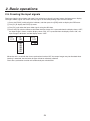
With the flip-flop (P/P) system, the PGM/A bus selected signals are always output as PGM images, and the PST/B
bus selected signals are always output as PVW (PST) images.
System
A/B
Video output
PGM
PVW (PST)
Before transition
PGM/A
PST/B
During transition
PGM/A, PST/B
PST/B
After transition completion
PST/B
PGM/A
With an A B transition
Lighting in red
Lighting in green
System
Flip-flop P/P
Video output
PGM
PVW (PST)
Before transition
PGM/A
PST/B
During transition
PGM/A, PST/B
PST/B
After transition completion
PGM/A
PST/B
Lighting in red
Lighting in green
14
2. Basic operations
2-1-3. Selecting the transition mode
Use the [BKGD] and [KEY] switches in the transition area to select the bus signals for which the transition is to
be executed. If the switches have been pressed at the same time, both switches are selected. The indicator of a
selected switch lights in amber.
The switches cannot be selected while a transition is being executed or suspended.
Use the [MIX] and [WIPE] switches in the transition area to select the background transition mode. Select one of
these switches, and the indicator of the selected switch lights in amber.
MIX always applies to key transitions whichever switch has been selected.
2-1-4. Manual transition (using the fader lever)
Operate the fader lever to execute transitions manually.
If the fader lever has been operated during auto transition, auto transition will be switched to manual operation as
soon as the fader position overtakes the amount of the transition being executed.
The bus tally LEDs on the left of the fader lever indicate the program bus output status.
Top LED only lights:
PGM/A bus output
Top and bottom LEDs light: PGM/A, PST/B output (during the transition)
Bottom LED only lights:
PST/B output
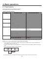
2-1-5. Auto transition
When the [AUTO] switch is pressed, the transition is executed automatically using the transition time which has
been set.
If the [AUTO] switch is pressed while the fader lever is at a midway position, the remaining transition will be
executed automatically using the transition time which has been set.
The auto transition time is set using the menu. It can be set separately for BKGD and KEY.
1 Press the [FUNC] switch to light its indicator, and press the [TIME] switch to display the TIME menu.
2 Turn [F1] to display the BKGD or KEY menu.
3 Turn [F4] to select the display unit using the UNIT item.
4 When frames (F) have been selected as the unit, turn [F2] or [F3] to set the transition time.
5When seconds (SEC) have been selected as the unit, turn [F2] to set the second units or [F3] to set the
frame units.
(With BKGD and seconds (SEC) as the display unit)
#,(%
53"/45*.& 6/*5
T G 4&$
(With KEY and frames (F) as the display unit)
,&:
53"/45*.& 6/*5
G '
Any time from 0 to 999f can be set. The time which can be set when seconds are used as the display unit
differs depending on the video format.
59i: max. 33s09f, 59p: max. 16s39f
50i: max. 39s24f, 50p: max. 19s49f
15
2. Basic operations
2-2. Wipe
2-2-1. Selecting the wipe pattern
Press one of the wipe pattern selector switches to select the desired wipe pattern
from among the nine patterns available. The indicator of the selected wipe pattern
selector switch lights in amber.
2-2-2. Selecting the wipe direction
Operate the transition direction selector switch (DIP switch) to select the wipe direction.
N:
For setting the wipe direction to the normal direction.
N/R:To switch the wipe direction between normal and reverse when the execution
of the transition has been completed.
R:
For setting the wipe direction to the reverse direction.
!
.
2
!
"
"
!
"
!
!
"
.2
!
"
"
!
!
"
"
2-2-3. Wipe decorations (border, soft effect)
Adding borders
Borders can be added to the wipe edges.
1Press the [FUNC] switch to light its indicator, and then press the [WIPE] switch to display the WIPE menu.
The BODR menu appears first.
2Turn [F2], and set the width of the border using the WIDT item.
A setting of “0” means that the border is OFF.
BODR
1/5
WIDT SOFT COLR
0
0 WHT
0—255 0—255
YLW
CYN
GRN
MGT
RED
BLE
BLK
USR1
USR2
USR3
USR4
16
2. Basic operations
Changing the soft effect amount
On the BODR menu, turn [F3], and set the soft effect amount using the SOFT item.
A setting of “0” means that the soft effect is OFF.
Setting the border color
On the BODR menu, turn [F4], and set the border color using the COLR item.
When USR1 to 4 (user colors) has been selected, the color can be adjusted on the USR1 to 4 menu.
Adjusting the border color
When USR1, 2, 3 or 4 has been selected, the border color can be adjusted.
Use of USR1 to 4 is shared by the color background, fill color and edge color.
1 Press the [FUNC] switch to light its indicator, and then press the [WIPE] switch to display the WIPE menu.
2 Turn [F1] to display the USR1 to 4 (user color) menu.
3 Turn [F2], [F3] or [F4] to adjust the color (HUE, SAT or LUM).
643
)6& 4"5 -6.
Operation
F2
F3
F4
Parameter
HUE
SAT
LUM
Description of setting
Hue
Saturation
Luminance
17
Setting range
0 to 359
0 to 100
0 to 108
2. Basic operations
2-3. Key
2-3-1. Selecting the key source
Selecting the key source signals
The signals assigned to crosspoints 1 to 7 can be used for the key source signals.
While holding down the [KEY-S] switch in the source selection area, press one of the B bus crosspoint switches [1]
to [7] to select the key source signal. The indicators of the [KEY-S] switch and selected crosspoint switch light in
amber.
Provide materials with white key-combined characters or patterns on a black background for the key source
signals. The keys may not be combined satisfactorily if the material has colors other than black and white.
Material with black characters on a white background, for example, can be reversed for use using the key invert
function.
<How key composition works>
Background
Output image
Key source
Key fill
18
2. Basic operations
2-3-2. Setting the key
Selecting the key type
1 Press the [FUNC] switch to light its indicator, and then press the [KEY] switch to display the KEY menu.
2 Turn [F1] to display the KEY menu (sub menu).
3 Turn [F2], and select the TYPE item.
SELF (self key/luminance key):The key signals are created from the luminance signals of the key fill
material. Since key fill signals are used as the key source, the signals
selected by the key source are ignored.
LIN (linear key/EXT key):
The key signals are created from the luminance signals of the key source.
TYPE
SELF (self key/luminance key)
LIN (linear key/EXT key)
,&:
KEY FILL
XPT1 to 7, FILL COLOR
XPT1 to 7, FILL COLOR
KEY SOURCE
Same as KEY FILL
XPT1 to 7
5:1& */7 178
-*/ 0'' "650
4&-' 0/ 0/
0''
Setting key invert
On the KEY menu (sub menu), turn [F3], and set to the key invert ON or OFF using the INV item.
Selecting key preview
Select whether to display the key preview for the PVW output.
On the KEY menu (sub menu), turn [F4] and set the PVW item.
ON:
Images with key effects added are output to PVW.
OFF:
Images with no key effects added are output to PVW.
AUTO: Preview images of the next transition are output to PVW.
2-3-3. Key adjustments
Adjust the key definition.
1 Press the [FUNC] switch to light its indicator, and then press the [KEY] switch to display the KEY menu.
2 Turn [F1] to display the K-ADJ menu.
3 Turn [F2], [F3] and [F4] to adjust the key definition.
,"%+ $-*1 ("*/ %&/4
Operation
F2
F3
F4
Parameter
CLIP
GAIN
DENS
Description of setting
Reference level for creating key signals
Key gain
Key density
19
Setting range
0 to 108
0 to 200
0 to 100
2. Basic operations
2-3-4. Selecting key fill
Selecting the key fill signals
In addition to the signals assigned to crosspoints 1 to 7, special fill colors can be used for the key fill signals.
While holding down the [KEY-F] switch in the source selection area, press one of the B bus crosspoint switches
1 to 7 to select the key fill signal. The indicators of the [KEY-F] switch and selected crosspoint switch light (in
amber). Bus images are not used when the fill color has been selected on the menu.
When the [KEY-F] switch in the source selection area is pressed, the menu display is switched to the FILL menu,
and the fill color can now be selected.
Selecting the fill color
The fill color is selected on the menu.
1 Press the [FUNC] switch to light its indicator, and then press the [KEY] switch to display the KEY menu.
2 Turn [F1] to display the FILL menu.
3 Turn [F2], and select COLR (special fill color) from the TYPE item.
4 Turn [F3], and select the fill color from the COLR item.
'*-
5:1& $0-3
#64 8)5
$0-3 :-8
$:/
(3/
.(5
3&%
#-&
#-,
643
643
643
643
20
2. Basic operations
Adjusting the fill color
The fill color can be adjusted when USR1 to 4 have been selected. Use of USR1 to 4 is shared by the border
color, color background and edge color.
1 Press the [FUNC] switch to light its indicator, and then press the [KEY] switch to display the KEY menu.
2 Turn [F1] to display the USR1 to 4 (user color) menu.
3 Turn [F2], [F3] and [F4] to adjust the color (HUE, SAT and LUM).
643
)6& 4"5 -6.
2-3-5. Key decorations
Setting the key edge
A border, shadow or other edge can be added to the key.
1Press the [FUNC] switch to light its indicator, and then press the [EDGE] switch to display the EDGE menu.
The EDGE menu (sub menu) appears first.
2 Turn [F2] to select the edge type.
OFF:
An edge is not added.
BODR (BORDER): A border is added around the entire edge.
DROP:
A diagonal border is added but only in the direction toward the bottom right of the key.
SHDW (SHADOW): A shadow is added but only in the direction toward the bottom right of the key.
OUTL (OUTLINE): An outline (only a border with no fill) is added.
3 Turn [F3] to set the edge width.
4 Turn [F4] to select the edge color.
EDGE
1/5
"/2$%2
TYPE WIDT COLR
OFF
2 WHT
BODR
DROP
SHDW
OUTL
0—4
YLW
CYN
GRN
MGT
RED
BLE
BLK
USR1
USR2
USR3
USR4
$2/0
3(!$/7
/54,).%
21
2. Basic operations
Adjusting the edge color
The edge color can be adjusted when USR1, 2, 3 or 4 has been selected. Use of USR1 to 4 is shared by the
border color, color background and fill color.
1 Press the [FUNC] switch to light its indicator, and then press the [EDGE] switch to display the EDGE menu.
2 Turn [F1] to display the USR1 to 4 (user color) menu.
3 Turn [F2], [F3] and [F4] to adjust the color (HUE, SAT and LUM).
643
)6& 4"5 -6.
22
2. Basic operations
2-4. Color background
The color background to be used by the bus can be set.
One color among the eight preset colors (WHITE, YELLOW, CYAN, GREEN, MAGENTA, RED, BLUE and BLACK)
and four user colors can be selected. HUE, SAT and LUM adjustments can be performed for the user colors.
1 Press the [FUNC] switch to light its indicator, and then press the [CBGD] switch to display the CBGD menu.
2 Turn [F2], and select the color using the COLR item.
$#(%
$0-3
8)5
:-8
$:/
(3/
.(5
3&%
#-&
#-,
643
643
643
643
Adjusting the color background
The background color can be adjusted when USR1, 2, 3 or 4 has been selected. Use of USR1 to 4 is shared by
the border color, color background, fill color and edge color.
1 On the [CBGD] menu, turn [F1] to display the USR1 to 4 (user color) menu.
2 Turn [F2], [F3] and [F4] to adjust the color (HUE, SAT and LUM).
643
)6& 4"5 -6.
23
2. Basic operations
2-5. Freezing the input signals
The input signals can be frozen and used. If any of the input signals has been frozen, the freeze status display
LED lights. While signals are frozen, the tally signals of the corresponding input will not be output.
1 Press the [FUNC] switch to light its indicator, and then press the [FRZ] switch to display the FRZ menu.
2 Turn [F1] to display the FRZ (2/2) menu.
3 Turn [F2], and select the input video signals using the SIG item.
4Press the [F4] switch to freeze or de-freeze the input image. If it is pressed when the display shows “OFF”,
the input image is frozen, and the display shows “ON”. If it is pressed when the display shows “ON”, the
input image is de-frozen, and the display shows “OFF”.
'3;
4*(
*/
'3;
0''
*/
*/
*/
*/
%7*
0/
When the unit is used with the frame synchronizer function OFF, the output images may be disturbed when
freezing is executed, but the frozen images will not be adversely affected.
The frame synchronizer function will automatically be switched ON.
24
2. Basic operations
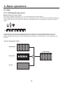
2-6. Frame memory
AUX output signals can be stored in the frame memory for use. Stored images can be used as the bus images by
assigning the FMEM signals using the crosspoint assignment process.
Images stored in the frame memory are also saved in the unit’s flash memory so they can be used even after the
power is turned off. Stored images have an 8-bit format so the image quality may appear rough at times.
1 Press the [FUNC] switch to light its indicator, and then press the [MEM] switch to display the MEM menu.
2 Turn [F1] to display the MEM menu.
3 Press the [F4] switch (EXEC) to store the still images in the frame memory.
'.&.
4*( .&. 4503
"69 '.&. &9&$
Images can also be captured into the frame memory from a PC via Ethernet.
For details on how to transmit them, refer to “5. Image transmission functions”.
25
2. Basic operations
2-7. Preset memory
Up to 10 panel settings can be stored in this memory.
The table below lists the settings which are stored.
<Table of stored preset memory>
Item
Crosspoint
Wipe
Transition area
Key
User color
Description of setting
A bus
B bus
KEY-S
KEY-F
AUX bus
Color background
Wipe pattern
Border width
Soft effect width
Border color
BKGD/KEY selection
MIX/WIPE selection
Auto transition time (BKGD)
Auto transition time (KEY)
Key type (TYPE)
Key adjustment (ADJ)
Invert ON/OFF
Fill color
Edge color
Edge ON/OFF (TYPE)
Edge width
User color 1 (HUE, SAT, LUM)
User color 2 (HUE, SAT, LUM)
User color 3 (HUE, SAT, LUM)
User color 4 (HUE, SAT, LUM)
Initial value (factory default)
1
1
1
1
1
WHITE
4 (center)
0
0
WHT
BKGD
MIX
30F
30F
LIN
GAIN: 100
CLIP: 0
DENS: 100
OFF
BLE
YLW
OFF
2
0, 0, 100
355, 100, 7
50, 100, 29
0, 0, 0
The data stored in the preset memory will not be initialized even when initializing is performed.
STORE: This is used to store the panel settings in the preset memory.
1Press the [FUNC] switch to light its indicator, and then press the [MEM] switch to display the MEM menu.
The PSMEM (1/3) menu appears first.
2Turn [F2], select “STOR” using the MODE item, turn [F3], and set the preset memory number using the NO.
item.
3 Press the [F4] switch (EXEC) to store the settings.
14.&. .0%& /0
4503 &9&$
3&$-
$-3
An asterisk ( ) appears at the left of the number when data has been saved in the preset memory.
26
2. Basic operations
RECALL: This is used to recall the preset memory data and change the panel settings.
1Press the [FUNC] switch to light its indicator, and then press the [MEM] switch to display the PSMEM (1/3)
menu.
2Turn [F2], select “RECL” using the MODE item, turn [F3], and set the preset memory number using the NO.
item.
3Press the [F4] switch (EXEC) to recall the settings.
If the asterisk ( ) is not displayed at the left of the preset memory number, the panel status will remain
unchanged even when the settings in the preset memory are recalled.
Recall settings can be selected for the crosspoint settings.
ENBL: The data stored in the preset memory is used.
DSBL: The data stored in the preset memory is not used, and the settings prior to recall are retained.
1Press the [FUNC] switch to light its indicator, and then press the [MEM] switch to display the PSMEM (1/3)
menu.
2 Turn [F1] to display the PSMEM (2/3) menu.
3 Turn [F2], and select crosspoint disable (DSBL) or enable (ENBL) using the XPT item.
14.&. 915
%4#&/#CLEAR: This is used to clear contents in the preset memory.
1Press the [FUNC] switch to light its indicator, and then press the [MEM] switch to display the PSMEM (1/3)
menu.
2Turn [F2], select “CLR” using the MODE item, turn [F3], and set the preset memory number using the NO.
item.
3Press the [F4] switch (EXEC) to clear the content.
When the memory settings are cleared, the asterisk ( ) at the left of the preset memory number will not be
displayed.
27
3. Setup
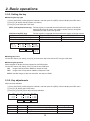
3-1. Setting the input signals
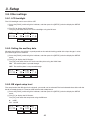
3-1-1. Setting the input signals (IN 1 to 5)
If HD has been selected as the system format, SDI or analog HD component can be selected for each input.
This selection is possible only when the HD analog board has been connected.
1Press the [FUNC] switch to light its indicator, and then press the [SETUP] switch to display the SETUP
menu.
2 Turn [F1] to display the IN1 to 5 menu.
3Turn [F2], select the input signals using the SIG item, turn [F3], and select SDI or ANLG (analog HD
component) using the MODE item.
4If analog HD component has been selected, turn [F4], and set the gain of the input signals using the GAIN
item. The gain can be set within the 30-step range, and the setting will result in changes of 2 dB.
The amount by which the gain changes per step is not the same for each step.
IN1-5 SIG MODE GAIN
1/15 IN1 SDI
IN2 ANLG -30—30
IN3
IN4
IN5
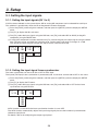
3-1-2. Setting the input signal frame synchronizer
The frame synchronizer can be set to ON or OFF for each input.
The input 6 (DVI input) frame synchronizer is permanently ON. It cannot be set from ON to OFF or vice versa.
1Press the [FUNC] switch to light its indicator, and then press the [SETUP] switch to display the SETUP
menu.
2 Turn [F1] to display the FS menu.
3Turn [F2], select the input signals using the SIG item, turn [F3], and select ON or OFF for the frame
synchronizer using the FS item.
'4
4*( '4
*/ 0/
*/ 0''
*/
*/
*/
AVDL function is active while the frame synchronizer function is set to OFF.
The AVDL function automatically adjusts the input image signal phase to the horizontal synchronization
reference signal phase.
For details, refer to “3-6. Adjusting the output signal phase”.
28
3. Setup
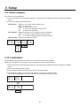
3-1-3. Setting the DVI input signals (IN6)
Selecting the signal system
Select the digital or analog system for the DVI input video signals.
DIG (digital):
Digital input signals of the DVI connector are effective.
ANLG (analog): Analog input signals of the DVI connector are effective.
1Press the [FUNC] switch to light its indicator, and then press the [SETUP] switch to display the SETUP
menu.
2 Turn [F1] to display the DVIIN menu.
3 Turn [F2], and select the signal system using the MODE item.
%7**/ .0%& 4$" %*( /03.
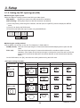
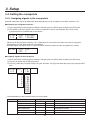
"/-( '6-Selecting the scaling method
XGA or SXGA can be input as the size. The frequency is fixed at 60 Hz.
NORM (normal):The size of the input images is increased or reduced while keeping their aspect ratio the
same.
FULL (full):The size of the input images is increased or reduced in accordance with the system
resolution. (The aspect ratio of the input images is not kept the same. The rate at which the
image size is increased or reduced in the vertical direction and in the horizontal direction
differs.)
On the DVIIN menu, turn [F3], and select the scaling method using the SCAL item.
<DVI input scaling size table>
DVI format
XGA
1024 768
Mode
HD/1080i
1920 1080
HD/720P
1280 720
NORM
FULL
SXGA
1280 1024
NORM
FULL
29
SD/PAL*2
720 576
SD/NTSC*1
720 480
*1: 480/59.94i, *2: 576/50i
3. Setup
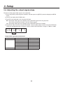
Adjustment
Adjust the clock/phase and position of the DVI input signals.
1Press the [FUNC] switch to light its indicator, and then press the [SETUP] switch to display the SETUP
menu.
2 Turn [F1] to display the DVIPH menu.
3Turn [F2] to adjust the clock/phase of the analog input signal using the CKPH item.
Adjust this setting so that the noise will be minimum level.
4 Turn [F3] to adjust the horizontal position using the HPOS item.
5 Turn [F4] to adjust the vertical position using the VPOS item.
%7*1) $,1) )104 7104
30
3. Setup
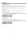
3-2. Setting the output signals
3-2-1. Types of output signals
There are three output signal types: PGM, PVW and AUX.
PGM:This is the main-line output of the switcher; images with wipe, mix, key and other effects added to them
are output.
PVW: This is the preview output which enables the next operation to be checked in advance.
AUX: Signals selected by the AUX bus are output.
3-2-2. Selecting the AUX signals
One of the crosspoints 1 to 7, PGM, PVW or CLN signals can be selected for the AUX bus.
To select a crosspoint signal, press one of the B crosspoint switches 1 to 7 while holding down the [AUX] switch.
The indicator of the selected switch lights (in amber), and the images are switched.
To select PGM, PVW or CLN signals, press one of the wipe pattern selector switches while holding down the
[AUX] switch. The indicator of the selected switch lights (in amber), and the images are switched.
When CLN signals have been selected, images with the key signals removed from the PGM signals are output.
31
3. Setup
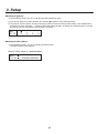
3-3. Selecting the video format
One system (input/output signal) video format can be selected. More than one format cannot be selected.
If HD is selected, SDI or HD analog component can be selected for each input. (See 3-1-1)
1Press the [FUNC] switch to light its indicator, and then press the [SETUP] switch to display the SETUP
menu.
2 Turn [F1] to display the FORMT menu.
3Turn [F2], select the format using the MODE item, and press the [F4] switch (EXEC) to enter the selection.
An asterisk ( ) appears at the left of the format currently selected.
'03.5 .0%&
J &9&$
J
Q
Q
J
J
Display
1080/59i
1080/50i
720/59p
720/50p
480/59i
576/50i
HD/SD
HD
HD
HD
HD
SD
SD
Signal format
1080/59.94i
1080/50i
720/59.94p
720/50p
480/59.94i
576/50i
Input signals
SDI / analog HD component
SDI / analog HD component
SDI / analog HD component
SDI / analog HD component
SDI
SDI
32
3. Setup
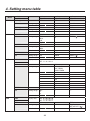
3-4. Setting the crosspoints
3-4-1. Assigning signals to the crosspoints
External video input signals and internally generated signals can be assigned to crosspoint switches 1 to 7.
Displaying the assignment statuses
1 Press the [FUNC] switch to light its indicator, and then press the [XPT] switch to display the XPT menu.
2The XPTAS (1/3) menu appears first, and the assignment statuses are displayed. The names of the
assigned signals are abbreviated on the display.
915"4 4*( #%
915 When one of the crosspoint switches 1 to 7 is held down for a long time, the name of the signal assigned is
displayed on the LCD while the button is held down.
Example: When crosspoint switch 1 is pressed (when the black signal has been assigned to this switch).
915"4 4*( #-,
915 Assigning signals to the crosspoints
1 Press the [FUNC] switch to light its indicator, and then press the [XPT] switch to display the XPT menu.
2 Turn [F1] to display the XPTAS (2/3) menu.
3Turn [F2], select the crosspoint switch using the XPT item, turn [F3] and select the input signal using the SIG
item.
915"4 915 4*(
*/
*/
*/
*/
*/
%7*
#-,
$#(%
$#"3
'.&.
The table below lists the materials which can be assigned.
Switch
XP1 to 7
Signal
INPUT1 to 5
DVIIN
BLACK
COLOR
BACKGROUND
COLOR BAR
FRAME MEMORY
Abbreviation
IN1 to 5
1 to 5
DVI
D
BLK
B
CBGD
G
CBAR
FMEM
C
F
33
Description
SDI or analog HD component
DVI-I input
Internally generated signal, black
Internally generated signal, color
background (matte)
Internally generated signal, color bar
Frame memory image
3. Setup
The table below lists the default settings.
Switch
XP1
XP2
XP3
XP4
XP5
XP6
XP7
Signal
BLACK
INPUT1
INPUT2
INPUT3
INPUT4
INPUT5
DVIIN
Description
Internally generated signal, black
External video input 1: SDI or analog HD component
External video input 2: SDI or analog HD component
External video input 3: SDI or analog HD component
External video input 4: SDI or analog HD component
External video input 5: SDI or analog HD component
External video input 6: DVI-I input
3-4-2. Setting the crosspoint switching
The timing at which the crosspoints are to be switched can be set.
ANY: The crosspoints are switched in the nearest field. This is suited to live applications.
F1:
The crosspoints are switched in field 1. This is suited to editing applications.
F2:
The crosspoints are switched in field 2. This is suited to editing applications.
1 Press the [FUNC] switch to light its indicator, and then press the [XPT] switch to display the XPT menu.
2 Turn [F1] to display the XPTSW menu.
3 Turn [F2], and select the switching timing using the TIMG item.
91548 5*.(
"/:
'
'
34
3. Setup
3-5. Setting the sync signals
The sync signals to be used by the system can be selected.
External sync:For synchronization with an external sync signal (gen-lock). The reference input signal is
looped through and output.
BBST: Black burst signal (vertical phase of 0H)
BBAD:Black burst signal
This can be selected when HD format signals are supplied.
(Vertical phase of 90H when the 59.94i or 59.94p format is selected;
vertical phase of 75H when the 50i or 50p format is selected)
TRI:Tri-level sync signal (vertical phase of 0H)
This can be selected when HD format signals are supplied.
Internal sync:For synchronization with an internal reference signal (INT). The REFOUT signal (black burst
signal) is output from the two reference connectors.
1Press the [FUNC] switch to light its indicator, and then press the [SETUP] switch to display the SETUP
menu.
2 Turn [F1] to display the REF menu.
3Turn [F2], select the sync signal using the SYNC item, and press the [F4] switch (EXEC) to enter the
selection.
An asterisk ( ) appears at the left of the reference signal currently selected.
REF
SYNC GL
5/15 BBST
BBAD
TRI
INT
EXEC
-
An asterisk ( ) appears at the GL item when operation is synchronized with the external or internal sync
signals.
A dash (–) appears at the GL item when operation is not synchronized with the external or internal sync
signals.
35
3. Setup
3-6. Adjusting the output signal phase
The phase of the output video signals can be adjusted.
1Press the [FUNC] switch to light its indicator, and then press the [SETUP] switch to display the SETUP
menu.
2 Turn [F1] to display the OUPHS menu.
3 Turn [F2], and select 0H or 1H using the SYS item.
0H:The output video signals are output to the system REF signal with using in-phase.
The frame synchronizer function is ON for all input signals.
1H: The output video signals are output to the system REF signal with 1H delay.
4Turn [F3] to adjust H phase using the HPHS item, and turn [F4] to adjust V phase using the VPHS item.
HPHS can be adjusted within a range of –0.5H to +0.5H and VPHS within a range of –100H to +100H.
061)4 4:4 )1)4
) 71)4
)
Output video signal phase adjustment
Phase
HPHASE
VPHASE
Video format
1080i/59i
1080/50i
720/59p
720/50p
480/59i
576/50i
Same for all formats
Adjustment range
−1100 to 1099
−1320 to 1319
−825 to 824
−990 to 989
−429 to 428
−432 to 431
−100 to 100
36
3. Setup
<Phase adjustment setup>
2%&
3YSTEM STANDARD
!PPROX (
!6$, 2ANGE
!PPROX ( TO (
!PPROX (
)NTERNAL &IXED $,
s ( /UTPUT
(
/UTPUT 0HASE 6ARIABLE 2ANGE
( 0HASE n( TO (
6 0HASE VERTICAL LINES
!6$, 2ANGE
)NTERNAL &IXED $,
!PPROX ( TO (
3HORTEST
/UTPUT (
!PPROX (
(
/UTPUT 0HASE 6ARIABLE 2ANGE
( 0HASE n( TO (
6 0HASE VERTICAL LINES
!6$, 2ANGE
)NTERNAL &IXED $,
!PPROX ( TO (
,ONGEST /UTPUT
(
!PPROX (
(
/UTPUT 0HASE 6ARIABLE 2ANGE
( 0HASE n( TO (
s ( /UTPUT
& DELAY FOR 2%& AND IN PHASE OUTPUT
!PPROX (
&3 2ANGE
-!8 LESS THAN APPROXIMATELY FRAME
)NTERNAL &IXED $,
/UTPUT 0HASE 6ARIABLE 2ANGE
( 0HASE n( TO (
6 0HASE VERTICAL LINES
2%& 0HASE 2EFERENCE
AVDL Range: Range for automatic phase adjustment.
37
6 0HASE VERTICAL LINES
3. Setup
3-7. Network settings
Set up the network for transmitting image files by Ethernet. For details on image transmission method, refer to
“5. Image transmission functions”.
The network initial setup is: IP address: 192.168.0.10, subnet mask: 255.255.255.0 and gateway: 0.0.0.0 (unused).
When using the host computer with settings matching the network setup, it is not necessary to setup via the
menu.
For the setting to take effect, the system must be rebooted. Turn the system’s power off and then back on.
Setting the IP address
1Press the [FUNC] switch to light its indicator, and then press the [SETUP] switch to display the SETUP
menu.
2 Turn [F1] to display the IP menu.
3 Turn [F2] to select the setting location. An asterisk ( ) appears at the setting location.
4Turn [F3] to set the number, and press the [F3] switch to enter the setting. If the setting is not entered even
though it has been changed, “ ! ” appears above the setting location, and when the setting location is moved
by turning [F2], the value prior to the change is restored.
*1
Setting the subnet mask
1 On the SETUP menu, turn [F1] to display the MASK menu.
2 Turn [F2] to select the setting location. An asterisk ( ) appears at the setting location.
3Turn [F3] to set the number, and press the [F3] switch to enter the setting. If the setting is not entered even
though it has been changed, “ ! ” appears above the setting location, and when the setting location is moved
by turning [F2], the value prior to the change is restored.
."4,
38
3. Setup
Setting the gateway
1 On the SETUP menu, turn [F1] to display the GW (Gateway) menu.
2 Turn [F2] to select the setting location. An asterisk ( ) appears at the setting location.
3Turn [F3] to set the number, and press the [F3] switch to enter the setting. If the setting is not entered even
though it has been changed, “ ! ” appears above the setting location, and when the setting location is moved
by turning [F2], the value prior to the change is restored.
(8
Setting the MAC address
1On the SETUP menu, turn [F1] to display the MAC menu.
The MAC address now appears.
(When the MAC address is “008045448000”.)
."$
39
3. Setup
3-8. Other settings
3-8-1. LCD backlight
The LCD backlight can be set to ON or OFF.
1Press the [FUNC] switch to light its indicator, and then press the [SETUP] switch to display the SETUP
menu.
2Turn [F1] to display the SYS menu.
Turn [F2], and select ON or OFF for the backlight using the BL item.
4:4
#7"/$ ##
0/ 0'' 0'' 0/ 3-8-2. Setting the ancillary data
Whether the ancillary data which is superimposed on the vertical blanking period of the input images is to be
passed through can be selected.
1Press the [FUNC] switch to light its indicator, and then press the [SETUP] switch to display the SETUP
menu.
2Turn [F1] to display the SYS menu.
Turn [F3], and select ON or OFF for the ancillary data using the VANC item.
ON:
The ancillary data is passed through.
OFF: The ancillary data is not passed through.
4:4
#7"/$ ##
0/ 0'' 0'' 0/ 3-8-3. BB signal setup level
The setup level of the BB signal in the internal sync mode can be selected. The level selected takes effect with the
59.94i or 59.94p format. It is fixed at 0 IRE with the 50i or 50p format.
1Press the [FUNC] switch to light its indicator, and then press the [SETUP] switch to display the SETUP
menu.
2Turn [F1] to display the SYS menu.
Turn [F4], and select the setup level using the BB item.
0:
0 IRE
7.5: 7.5 IRE
4:4
#7"/$ ##
0/ 0'' 0'' 0/ 40
3. Setup
3-9. Status displays
The statuses can be displayed.
1Press the [FUNC] switch to light its indicator, and then press the [SETUP] switch to display the SETUP
menu.
2 Turn [F1] to display the STATS menu.
ALM (alarm):
Indicates a fan and/or power supply alarm.
FAN
Fan alarm
POWR Power supply alarm
F, P
Fan alarm and power supply alarm
NO
No alarm information
OPT (option): Indicates whether or not an optional board is provided.
ANLG The HD analog board has been inserted.
NO
The HD analog board has not been inserted.
VER (version): Indicates the software version.
45"54 "-. 015 7&3
'"/ "/-( 1083 /0
' 1
/0
3-10. Initialization
All the settings except the preset memory can be returned to the factory defaults.
(When they are returned, the images in the frame memory will also be initialized.)
1Press the [FUNC] switch to light its indicator, and then press the [SETUP] switch to display the SETUP
menu.
2 Turn [F1] to display the INIT menu.
3 Press [F2] to initialize the settings. The “INIT?” message appears.
4To initialize the settings, turn [F2] to select YES, and then press the [F2] switch.
To cancel the initialization, turn [F2] to select NO, and then press the [F2] switch.
*/*5 */*5
&9&$
*/*5 */*5
/0
:&4
41
4. Setting menu table
A setting is entered when an item displayed (
) is selected and then the [F1], [F2], [F3] or [F4] switch is pressed.
(It will not be entered unless the switch is pressed.)
Menu
TIME
WIPE
Submenu
Parameter 1
Turn F1 to select.
Turn F2 to select.
BKGD
Parameter
TRANSTIME
Setting range 0 to 13s
1/2
Default value —
Parameter
TRANSTIME
Setting range 0 to 13s
30f
KEY
2/2
BODR
1/5
Default value —
Parameter
WIDT
Setting range 0 to 255
30f
SOFT
0 to 255
Default value
Parameter
Setting range
Default value
Parameter
Setting range
Default value
Parameter
Setting range
Default value
Parameter
Setting range
Default value
Parameter
Setting range
0
SAT
0 to 100
0
SAT
0 to 100
100
SAT
0 to 100
100
SAT
0 to 100
0
—
—
Parameter 3
Turn F4 to select.
UNIT
F
SEC
SEC
UNIT
F
SEC
SEC
COLR
WHT, YLW, CYN
GRN, MGT, RED
BLE, BLK
USR1 to 4
WHT
LUM
0 to 108
100
LUM
0 to 108
7
LUM
0 to 108
29
LUM
0 to 108
0
—
—
SAT
0 to 100
0
SAT
0 to 100
100
SAT
0 to 100
100
LUM
0 to 108
100
LUM
0 to 108
7
LUM
0 to 108
29
USR1(*)
2/5
USR2(*)
3/5
USR3(*)
4/5
USR4(*)
5/5
CBGD
CBGD
1/5
USR1(*)
2/5
USR2(*)
3/5
USR3(*)
4/5
0
HUE
0 to 359
0
HUE
0 to 359
355
HUE
0 to 359
50
HUE
0 to 359
0
COLR
WHT, YLW, CYN
GRN, MGT, RED
BLE, BLK
USR1 to 4
Default value WHT
Parameter
HUE
Setting range 0 to 359
Default value 0
Parameter
HUE
Setting range 0 to 359
Default value 355
Parameter
HUE
Setting range 0 to 359
Default value 50
42
Parameter 2
Turn F3 to select.
0 to 999f
0 to 999f
4. Setting menu table
Menu
CBGD
KEY
Submenu
Turn F1 to select.
USR4(*)
Parameter
5/5
Setting range
Default value
KEY
Parameter
1/7
Setting range
K-ADJ
2/7
FILL
3/7
KEY-F Link
from switch
USR1(*)
4/7
USR2(*)
5/7
USR3(*)
6/7
USR4(*)
7/7
EDGE
EDGE
1/5
USR1(*)
2/5
USR2(*)
3/5
Default value
Parameter
Setting range
Default value
Parameter
Setting range
Parameter 1
Turn F2 to select.
HUE
0 to 359
0
TYPE
SELF
LIN
Parameter 2
Turn F3 to select.
SAT
0 to 100
0
INV
ON
OFF
LIN
CLIP
0 to 108
0
TYPE
BUS
COLR
OFF
GAIN
0 to 200
100
COLR
WHT, YLW, CYN
GRN, MGT, RED
BLE, BLK
USR1 to 4
BLE
SAT
0 to 100
0
SAT
0 to 100
100
SAT
0 to 100
100
SAT
0 to 100
0
WIDT
0 to 4
Default value
Parameter
Setting range
Default value
Parameter
Setting range
Default value
Parameter
Setting range
Default value
Parameter
Setting range
Default value
Parameter
Setting range
BUS
HUE
0 to 359
0
HUE
0 to 359
355
HUE
0 to 359
50
HUE
0 to 359
0
TYPE
OFF
BODR
DROP
SHDW
OUTL
Default value OFF
Parameter
HUE
Setting range 0 to 359
Default value 0
Parameter
HUE
Setting range 0 to 359
Default value 355
43
2
SAT
0 to 100
0
SAT
0 to 100
100
Parameter 3
Turn F4 to select.
LUM
0 to 108
0
PVW
ON
OFF
AUTO
AUTO
DENS
0 to 100
100
LUM
0 to 108
100
LUM
0 to 108
7
LUM
0 to 108
29
LUM
0 to 108
0
COLR
WHT, YLW, CYN
GRN, MGT, RED
BLE, BLK
USR1 to 4
YLW
LUM
0 to 108
100
LUM
0 to 108
7
4. Setting menu table
Menu
EDGE
MEM
Submenu
Turn F1 to select.
USR3(*)
Parameter
4/5
Setting range
Default value
USR4(*)
Parameter
5/5
Setting range
Default value
PSMEM
Parameter
1/3
Setting range
PSMEM
2/3
FMEM
3/3
XPT
XPTAS
1/3
XPTAS
2/3
Parameter 1
Turn F2 to select.
HUE
0 to 359
50
HUE
0 to 359
0
MODE
STOR
RECL
CLR
Default value STOR
Parameter
XPT
Setting range DSBL
ENBL
Default value DSBL
Parameter
SIG
Setting range AUX
Default value
Display only
FRZ
FRZ
1/2
FRZ
2/2
1 to 10
Parameter
XPT
Setting range 1 to 7
Parameter 3
Turn F4 to select.
LUM
0 to 108
29
LUM
0 to 108
0
EXEC (
1
—
—
—
—
—
—
MEM
FMEM
—
STOR
—
—
SIG: B 12 3 4 5 D
XPT: 12 3 4 5 6 7
SIG
IN1 to 5, DVI
BLK, CBGD,
CBAR, FMEM
BLK
IN1
IN2
IN3
IN4
IN5
DVI
—
—
Default value
XPTSW
3/3
Parameter 2
Turn F3 to select.
SAT
0 to 100
100
SAT
0 to 100
0
NO.
EXEC (
)
)
—
—
—
1
2
3
4
5
6
7
Parameter
TIMG
Setting range ANY
F1
F2
Default value ANY
—
Display only
FRZ:
XPT: 12 3 4 5 6 7
—
—
—
—
—
—
—
—
—
Parameter
SIG
Setting range IN1 to 5, DVI
—
—
FRZ
Toggling between
ON and OFF (
)
Default value
—
OFF
IN1 to 5, DVI
44
—
4. Setting menu table
Menu
SETUP
Submenu
Parameter 1
Turn F1 to select.
Turn F2 to select.
IN1–5
Parameter
SIG
1/15
Setting range IN1 to 5
Default value
DVIIN
2/15
FS
3/15
FORMT
4/15
REF
5/15
IN1 to 5
Parameter
MODE
Setting range DIG
ANLG
Default value DIG
Parameter
SIG
Setting range IN1 to 5
Default value IN1 to 5
Parameter
MODE
Setting range
1080/59i
1080/50i
720/59p
720/50p
480/59i
576/50i
Default value 1080/59i
Parameter
SYNC
Setting range
BBST
Parameter 2
Turn F3 to select.
MODE
SDI
ANLG
SDI
ANLG
Parameter 3
Turn F4 to select.
GAIN
–30 to 30
SCAL
NORM
FULL
NORM
FS
ON
OFF
ON
—
—
—
—
—
GL
—
—
—
0
—
—
—
—
—
EXEC (
EXEC (
)
)
—
OUPHS
6/15
Default value
Parameter
Setting range
IP
7/15
MASK
8/15
GW
9/15
MAC
10/15
BUS
11/15
Default value
Setting range
Default value
Setting range
Default value
Setting range
Default value
Display only
Default value
Parameter
Setting range
Default value
BBAD
TRI
INT
BBST
—
SYS
HPHS
0H
–1320 to 1319
1H
1H
0
Cursor movement
0 to 255
192.168.0.10
Cursor movement
0 to 255
255.255.255.0
Cursor movement
0 to 255
0.0.0.0
12-digit address display
—
MODE
—
A/B
—
P/P (PGM/PST)
P/P
—
45
—
VPHS
–100 to 100
0
—
—
—
4. Setting menu table
Menu
SETUP
Submenu
Parameter 1
Turn F1 to select.
Turn F2 to select.
SYS
Parameter
BL
Setting range ON
12/15
OFF
Default value ON
DVIPH
Parameter
CKPH
13/15
Setting range –16 to 15
Default value 0
INIT
Parameter
INIT
14/15
Setting range EXEC (
)
Parameter 2
Turn F3 to select.
VANC
ON
OFF
OFF
HPOS
–100 to 100
0
—
Parameter 3
Turn F4 to select.
BB
0
7.5
7.5
VPOS
–100 to 100
0
—
STATS
15/15
OPT
ANLG
NO
VER
Version number
Parameter
Display only
ALM
FAN
POWR
F, P
NO
* The same USR1 to USR4 parameters are used for the WIPE menu, CBGD menu, KEY menu and EDGE menu.
46
5. Image transmission functions
This unit comes with a function for transmitting still images from the host computer to the unit via Ethernet and
a function for importing still images from the unit into the host computer. The image transmission program must
be installed in the host computer from the CD-ROM supplied in order to use these functions. For details on
installation, refer to “How to install the program”.
Specifications
Run the image transmission program (HS300 Tool) in a host computer which satisfies the following conditions.
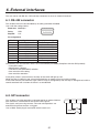
• Operating system: Windows 2000 or Windows XP
• Processor:
Pentium III, 1 GHz or better recommended
• RAM:256 MB or more recommended
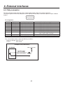
• Hard disk drive:
At least 50 MB of free memory
• Ethernet:
10BASE-T or 100BASE-TX
• Display:
TrueColor (24 bit, 32 bit color), 800 600 dots or more
The image formats supported include bitmap (bmp), JPEG (jpg), TIFF (tif), GIF (gif) and PNG (png).
The image transmission program is equipped with a function for automatically converting images into the specified
video format size.
Connections
Connect this unit to Ethernet using a twisted pair cable. Use a LAN crossover cable to connect the unit with the
host computer directly. Use a LAN straight cable to connect to Ethernet using a hub or other equipment.
For details on network setup such as IP addresses, refer to [3-7 Network settings].
Transmitting images uses network capacity which may result in other connected devices possibly being affected
when connecting to Ethernet through a hub and other equipment.
LAN crossover cable
LAN straight cable
LAN straight cable
HUB
47
5. Image transmission functions
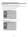
How to install the program
This section describes how to install the image transmission program (HS300 Tool).
Windows XP is used as the host computer’s operating system in the example given here.
1.Insert the CD-ROM supplied with the unit into the CD-ROM drive of the host computer in which the program
will be installed. (Here, E: will serve as the name of this drive for example.)
2. Execute the setup program (E:\HS300TOOL\ENG\SETUP.EXE).
3. The installer now starts up so follow its instructions to proceed.
4.The Setup Complete screen appears to indicate that installation is complete.
Click [Finish] to close the window.
48
5. Image transmission functions
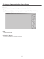
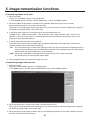
Operation
This section describes how to operate the image transmission program (HS300 Tool).
<Startup>
On the Start menu of Windows, select [Programs] [Panasonic] [AV-HS300Tool] [HS300Tool].
The main screen now appears.
<Exit>
Click the [CLOSE] button.
<Setting the IP address>
Set the unit’s IP address in the IP Address setting box.
49
5. Image transmission functions
<Transmitting images to the unit>
1.Select the mode.
Check that “To HS300” appears in the [Mode] field.
If “From HS300” appears instead, click the Mode button so that “To HS300” appears.
2.When the [Select Image] button is clicked, the file selection dialog box appears on the screen.
Select the image file to be transmitted, and click [OK].
The image is now displayed in the image display area, and its horizontal and vertical dimensions appear in
the [Width] and [Height] fields at the bottom right.
3.In the [Size] field, select the size of the image to be transmitted to the unit.
HD1080 (1920 1080), HD720 (1280 720), SD NTSC (720 488) or SD PAL (720 576) can be
selected as the size. If the image is in a different video format from the ones supported by the unit, the
output will not be displayed properly.
4.In the [Aspect] field, select the scaling method.
If the size of the image to be transmitted and the selected image differ, the image will be automatically
scaled according to one of the following methods.
Full:The size of the image is increased or reduced so that it fits the size selected in the [Size] field. If the
aspect ratio of the image to be transmitted differs from that of the selected image, the ratio between
the horizontal and vertical dimensions will be changed.
Keep:The image is expanded or reduced while its original aspect ratio is kept unchanged.
Any empty spaces in the image will appear black.
5. Click the [Send] button to transmit the image to the unit.
<Transmitting images from the unit>
1.Select the mode.
Check that “From HS300” appears in the [Mode] field.
If “To HS300” appears instead, click the Mode button so that “From HS300” appears.
2.When the [Get] button is clicked, the image is imported from the unit.
The image is now displayed in the image display area, and its horizontal and vertical dimensions appear in
the Width and Height fields at the bottom right.
3.When the [Save Image] button is clicked, the file save dialog box appears on the screen. Select the image
file to be transmitted, and click [Save].
50
6. External interfaces
This unit comes with RS-422, GPI and tally connectors to serve as external interfaces.
6-1. RS-422 connector
This enables the unit to be controlled by an editing controller AG-A850.
Use it with the settings below.
Baud rate: 38400 bps
Parity:
ODD
Stop bit:
1 bit
Pin assignment
Pin No.
1
2
3
4
5
6
7
8
9
Signal name
FRAME GROUND
TXD –
RXD +
GROUND
NC
GROUND
TXD +
RXD –
FRAME GROUND
Description of signal
Frame ground
Send data (–)
Receive data (+)
Ground
Not used
Ground
Send data (+)
Receive data (–)
Frame ground
The following lists the functions which can be controlled by AG-A850. (Compliant with the GVG protocol)
• Crosspoint switch
• Wipe pattern selection
• Transition mode (MIX/WIPE) selection
• Auto transition time setting
• Auto transition execution
If the [AUX] switch is pressed twice, the lamp of the switch will light up red.
While the lamp is lighted up red, control exercised from an external source can be canceled.
If the same switch is pressed twice again while its lamp is still lighted up red, the lamp is extinguished, and the
control exercised from an external source is re‑established.
6-2. GPI connector
This enables auto take operations to be executed by an external device.
Auto transitions are executed at the fall of the GPI signals.
The signals are input using contacts. The auto take operations are
executed using these contacts as triggers.
Use an M3.5 stereo plug for connection with the main unit.
AUTO TAKE
AUTO TAKE
51
6. External interfaces
6-3. Tally connector
The tally connector comes with tally output, output enable, power supply or fan alarm output pins.
The output signals from the tally output pins are for lighting the tally lamps, and these outputs are open collector
outputs.
1
2
6
3
7
4
8
5
9
Pin assignment
Pin No.
1
2
3
4
5
6
7
Signal name
IN1
IN2
IN3
IN4
IN5
IN6
ENABLE
Input/output
Open collector output
Open collector output
Open collector output
Open collector output
Open collector output
Open collector output
Input
8
9
ALARM
GROUND
Open collector output
GROUND
Pins 1 to 6 and pin 8 must satisfy the following conditions:
Dielectric strength: Max. DC 24 V
Current:
Max. 50 mA
Example of tally connections
AV-HS300G
(Max. voltage: 24V)
Tally, Alarm output
(IN1 to 6, ALARM)
(Max. current: 50mA)
Tally LED
GROUND
52
Description of signal
Tally output of input video 1
Tally output of input video 2
Tally output of input video 3
Tally output of input video 4
Tally output of input video 5
Tally output of input video 6
Enable signal of tally output
Open: Output; GND: no output
Fan alarm or power supply alarm output
Ground
7. Connections
Connections when implementing gen-lock
(frame synchronizer OFF)
Signal Generator
SDI (HD)
HD camera
SDI (HD)
HD camera
HD Component
HD component
monitor
SDI (HD)
HD camera
SDI (HD)
HD SDI monitor
SDI (HD)
VTR
SDI (HD)
HD SDI monitor
SDI
HD camera
Multi-format
live switcher
AV-HS300G
PC
DVI or VGA
AC adapter
AW-PS505A
53
7. Connections
Connections when not implementing gen-lock
(frame synchronizer ON)
• Example where the optional HD analog board is used
SDI (HD)
HD camera
SDI (HD)
HD camera
HD Component
HD component
monitor
HD Component
SDI (HD)
HD camera
HD SDI monitor
HD Component
DVD player
HD component
monitor
HD Component
VTR
HD Component
Multi-format
live switcher
AV-HS300G
PC
DVI or VGA
Optional HD analog board
54
AC adapter
AW-PS505A
8. Appearance
Unit: inch (mm)
4-1/16
(103.5)
3/16
(5)
9-1/2
(240)
16-1/8
(410)
55
Specifications and standard accessories
Specifications
Inputs
Video inputs 6 (SDI 5, DVI-I 1, analog HD 5 [optional])
Reference 1
Outputs
Video outputs 3 (PGM, PVW, AUX)
PGM: SDI 2 outputs, analog HD 1 output
PVW: SDI 1 output, analog HD 1 output
AUX: SDI 2 outputs, analog HD 1 output
Reference 1
Signal formats
SD: 480/59.94i, 576/50i
HD: 1080/59.94i, 1080/50i, 720/59.94p, 720/50p
Signal processing
Y:Cb:Cr 4: 2: 2, 10 bit
RGB 4:4:4, 8 bit
ME number
1ME
SDI inputs
HD: Serial digital (SMPTE 292M)
SD: Component digital (SMPTE 259M)
IN1 to 5 (with active through)
HD [SMPTE 292M (BTA S-004B) standard complied with]
• 0.8 Vp-p 10 % (75 )
• Input return loss
More than 15 dB (5 MHz to 750 MHz)
More than 10 dB (750 MHz to 1.5 GHz)
• Automatic equalizer More than 100 m (5C-FB)
SD [SMPTE 259M standard complied with]
• 0.8 Vp-p 10 % (75 )
• Input return loss
More than 15 dB (5 MHz to 270 MHz)
• Automatic equalizer200 m (5C-2V)
SDI outputs
HD: Serial digital (SMPTE 292M)
SD: Component digital (SMPTE 259M)
PGM, PVW, AUX
HD [SMPTE 292M (BTA S-004B) standard complied with]
• Output return loss More than 15 dB (5 MHz to 750 MHz)
More than 10 dB (750 MHz to 1.5 GHz)
• Output level
0.8 Vp-p 10 %
• Rise time
Less than 270 ps
• Fall time
Less than 270 ps
• Difference between rise time and fall time
Within 100 ps
• Alignment jitter
Less than 0.2 UI (130 ps)
• Timing jitter
Less than 1.0 UI
• Eye aperture ratio More than 90 %
• DC offset
0 0.5 V
56
Specifications and standard accessories
SDI outputs
SD [SMPTE 259M standard complied with]
• Output return loss More than 15 dB (5 MHz to 270 MHz)
• Output level
0.8 Vp-p 10 %
• Rise time
Less than 1.5 ns
• Fall time
Less than 1.5 ns
• Difference between rise time and fall time
Less than 0.5 ns
• Jitter
Less than 0.2 UI
Analog HD input
(option)
HD analog component Y/Pb/Pr (1.0 Vp-p, 75 )
Analog HD output
HD analog component Y/Pb/Pr (1.0 Vp-p, 75 )
IN1 to 5
PGM, PVW, AUX
DVI-I input
SXGA 1280 1024, XGA 1024 768 (60 Hz)
Key input
1 input from video inputs
Reference input
Black burst or Tri-level Sync (with loop-through) 1
Reference output
In gen-lock mode: loop-through output 1,
In internal sync mode: black burst 2
Video delay time
Frame synchronizer OFF
1H
Frame synchronizer ON
1F
Ethernet
100 Mbps/10 Mbps 1
Image transmission function available
(provided with transmission program)
Serial communication
interface
RS-422A (D-SUB 9-pin) 1
Tally output
Open collector outputs (negative logic) 1 to 6
GPI
Auto take 1
Control I/O
Ambient operating
temperature
32 °F to 104 °F (0 °C to 40 °C)
Humidity
10 % to 90 % (no condensation)
Power supply
DC 12 V 2 V
Power consumption
46.8 W
Dimensions
(W H D)
16-1/8" 4-1/16" 9-1/2" (410 103.5 240 mm)
[Excluding protrusions]
Weight
7.1 lbs. (3.2 kg)
Standard accessories
Operating instructions ................................................................. 1
Operation manual / Image transmission program install CD ....... 1
Optional accessories
HD analog board AV-HSB300
Refer to the operating instructions that come with the HD analog board for details about the installation method.
57
Appendix (glossary)
Defined below are the terms used in this manual.
Word
Explanation
AB Bus system
A bus control mode. By executing a transition, the A bus and B bus signals are
output to the program images alternately.
Ancillary Data
The auxiliary data other than the video signals which is transmitted inside the
data stream of the video serial interface. The data superimposed on the vertical
blanking period is referred to as the V ancillary data (VANC).
Aspect ratio
The ratio between the horizontal and vertical dimensions of an image or screen.
It is 16:9 for the HD format and 4:3 for the SD format.
AUX
[Auxiliary Bus]
A spare bus which can be switched by signals other than the main line output
signals.
AVDL
[Automatic Video Delayline]
A function to automatically adjust the input image signal phase to the horizontal
synchronization reference signal phase.
BB
[Black burst]
The black burst signal. A full-screen black level composite signal which is used
as the reference signal for gen-lock.
Border
The area or margin that is added to the edge of a wipe or key.
Its width and color can be adjusted. The defocusing of the area around a border
is referred to as the soft effect.
Clip
The threshold level of the luminance when key signals are created from a key
source.
Color Background
The signals which are output from the internal color generator and used as the
background image.
Density
A parameter which is used to adjust the density of the key signals.
DVI
[Digital Visual Interface]
A digital video interface standard.
DVI-I can handle both digital signals and analog signals.
Ethernet
A computer network standard; the 10BASE-T (10 Mbps), 100BASE-TX
(100 Mbps) or other such standard based on the transmission speed.
Flip Flop system
(PGM/PST system)
A bus control mode. The signals selected by the program bus are always output
as the program images. By executing a transition, the program bus and preset
bus signals are switched over.
Frame Memory
A memory which can hold the video signals equivalent to one frame.
Frame Synchronizer
A function which enables the asynchronous video signal input to be switched.
Freeze
A function which continues the display of the same image, creating the
impression that the image has been “frozen”.
Gain
A parameter which adjusts the defocusing of the edges of the key signals.
58
Appendix (glossary)
Word
Explanation
Genlock
A function for synchronizing the video signals using an external sync signal as
the reference.
GPI
[General Purpose Interface]
Interface signals which control auto transition from an external source.
IRE
A unit used for video signal levels.
The setup level (black level) of the signals is expressed as 0 IRE, 7.5 IRE, etc.
Hue
The color tone of the video signals.
Key Edge
The border or shadow added to the edges of keys.
Key Fill
The signal that uses key combination processing to fill in the areas left blank by
the key signals.
Key invert
A function which inverts the key signals.
Key Source
The video signals for creating the key signals.
Linear Key
The function which combines keys using monochrome key signals with
gradations in its outlines as a reference.
Lum
[Luminance]
The brightness portion of the video signals.
Luminance Key
The function which creates key signals based on the luminance (brightness)
information of the video signals to combine keys.
ME
[Mix Effect]
A video effect device which combines a number of video signals to create mix,
wipe, key and other video signals.
Mix
The picture-changing effect produced by overlapping one image with the next.
It is also referred to as “dissolve”.
PVW
[Preview]
The function for checking ahead of time the image which will be output after the
next transition. The image is output from the PVW system.
PGM
[Program Bus]
The bus which always carries the program output signals.
PST
[Preset Bus]
The bus which carries the program output signals after the next background
transition.
Preset Memory
The memory in which the control panel statuses can be saved and recalled.
The switch selection statuses as well as the border, color and other setting
information can be saved in this memory.
RS-422
A serial interface standard. It is the interface used to control the switcher from
an editor or other external device.
Sat
[Saturation]
This refers to the intensity of the color chrominance level of video signals.
59
Appendix (glossary)
Word
Explanation
SDI
[Serial Digital Interface]
The standard by which video signals in various SD and HD formats are
transmitted along a single coaxial cable.
Self Key
A function that creates key signals from key fill signals for combining keys.
Tally
The signal which outputs the program output statuses of the input signals to an
external device. The LED that indicates the program output status on the control
panel is also referred to as tally.
Transition
A function that switches from one image to another.
Wipe, mix and other effects are available for the images during switching.
Tri-level Sync
The sync signal used for HD formats.
Wipe
A video effect in which one image is gradually replaced by another as the
boundary between the two is moved using a preselected pattern.
60
Memo
Memo
PANASONIC BROADCAST & TELEVISION SYSTEMS COMPANY
UNIT COMPANY OF PANASONIC CORPORATION OF NORTH AMERICA
Headquarters:
3 Panasonic Way 4E-7, Secaucus, NJ 07094 (201) 348-5300
EASTERN ZONE:
3 Panasonic Way 4E-7, Secaucus, NJ 07094 (201) 348-7196
WESTERN ZONE:
3330 Cahuenga Blvd. West, Los Angeles, CA 90068 (323) 438-3608
Government office:
(201) 348-7587
Broadcast PARTS INFORMATION & ORDERING:
9:00 a.m. – 5:00 p.m. (PST) (800) 334-4881/24 Hr. Fax (800) 334-4880
Emergency after hour parts orders (800) 334-4881
TECHNICAL SUPPORT:
Emergency 24 Hour Service (800) 222-0741
Panasonic Canada Inc.
5770 Ambler Drive, Mississauga, Ontario L4W 2T3 (905) 624-5010
Panasonic de Mexico S.A. de C.V.
Av angel Urraza Num. 1209 Col. de Valle 03100 Mexico, D.F. (52) 1 951 2127
Panasonic Puerto Rico Inc.
San Gabriel Industrial Park, 65th Infantry Ave., Km. 9.5, Carolina, Puerto Rico 00630 (787) 750-4300
© 2006 Matsushita Electric Industrial Co., Ltd. All rights reserved.
Matsushita Electric Industrial Co., Ltd.
Web Site: http://panason i c . n e t
Printed in Japan
VQTB0146-3
F1106S4037 D