1
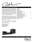
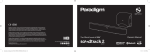
R
T E
C H
N O L O G Y
Wireless Subwoofer Receiver
Wireless Transmitter
Owners Manual / Installation Instructions
WL-RX SUB · WL-3TX
WL-RX SUB
WL-3TX
(Optional)
DESCRIPTION
The WL-RX SUB receiver works with the WL-3TX wireless transmitter to make any powered
subwoofer with a line level input into a wireless sub. This transmitter and receiver
combination will accurately reproduce low-frequency sounds and music without interference
or compression over distances up to 150 feet. The receiver’s compact size allows for easy
and clean installation with almost any powered subwoofer. Multiple subs can be used in a
single system (by adding receivers), and multiple systems can be used in the same home or
building (by using 1-3 transmitters set to different channels).
Please note: While the effective range of the WL-3TX and WL-RX SUB is normally greater
than 150 feet, the range distance can be significantly affected by walls, ceilings, and other
obstacles. Phase Technology recommends using the transmitter and receiver in either the
same or adjacent rooms for best results.
CONTENTS:
SAFETY PRECAUTIONS2
WL-RX SUB INSTALLATION/SETUP
3
WL-3TX INSTALLATION/SETUP3
MULTIPLE SUBWOOFERS3
TROUBLESHOOTING3
SPECIFICATIONS4
WARRANTY4
WL-RX SUB FEATURES:
•Designed for use with the PHASE TECHNOLOGY WL-3TX wireless multi-channel
transmitter
•Usable with most powered subwoofer
•Signal sensing auto link-up indicator
•Selectable wireless 3-channel operation
•Interference free 2.4 GHz operation
•Long range operation
•Wireless uncompressed audio streaming
•Line level subwoofer output connection
•Allows multiple receiver/subwoofer operation from one transmitter
•Allows up to 3 different systems to operate independently.
Phase Technology 8650 College Boulevard
Overland Park, Kansas 66210 (866) 663-9770
www.phasetech.com
An MSE Audio Group company www.mseaudio.com
SAFETY INSTRUCTIONS
CAUTION
RISK OF ELECTRIC
SHOCK
DO NOT OPEN
!
CAUTION: To reduce the risk of electric shock, do not remove
cover (or back). No user-serviceable parts inside. Refer
servicing to qualified service personnel.
Explanation of Graphical Symbols
The lightning flash with arrowhead symbol, within an equilateral triangle,
is intended to alert you to the presence of un-insulated “dangerous
voltage: within the product’s enclosure that may be of sufficient
magnitude to constitute a risk of electric shock to persons.
!
The exclamation point within an equilateral triangle is intended to alert
you to the presence of important operating and maintenance (servicing)
instructions in the literature accompanying the appliance.
1. Read Instructions - All the safety and operating instructions should be read before the
appliance is operated.
2. Retain Instructions - The safety and operating instructions should be retained for future
reference.
3. Heed Warnings - All warnings on the appliance and in the operating instructions should
be adhered to.
4. Follow Instructions - All operating and other instructions should be followed.
5. Water and Moisture - The appliance should not be used near water - for example, near
a bathtub, washbowl, kitchen sink, laundry tub, in a wet basement, or near a swimming
pool, etc.
6. Carts and Stands - The appliance should be used only with a cart or stand that is
recommended by the manufacturer.
PORTABLE CART WARNING
7. Wall or Ceiling Mounting - The appliance should be mounted to a wall or ceiling only as
recommended by the manufacturer.
8. Ventilation - The appliance should be situated so that its location or position does not
interfere with its proper ventilation. For example, the appliance should not be situated on
a bed, sofa, rug, or similar surface that may block the ventilation openings; or placed in a
built-in installation, such as a bookcase or cabinet that may impede the flow of air through
the ventilation openings.
9. Heat - The appliance should be situated away from heat sources such as radiators,
stoves, or other appliances that produce heat.
10. Power Source - The appliance should be connected to a power supply only of the type
described in the operating instructions or as marked on the appliance.
11. Power Cord Protection - Power supply cords should be routed so that they are not
likely to be walked on or pinched by items placed up or against them, paying particular
attention to cords at plugs, convenience receptacles, and the point where they exit from
the appliance.
12. Cleaning - The appliance should be cleaned only as recommended by the
manufacturer.
13. Nonuse Periods - The power cord of the appliance should be unplugged from the
outlet when left unused for a long period of time.
14. Object and Liquid Entry - Care should be taken so that neither objects fall nor liquids
spill into the inside of the appliance.
15. Damage Requiring Service - The application should be serviced by qualified service
personnel when:
a. the power supply cord or the plug has been damaged,
b. Objects have fallen onto or liquid has been spilled into the appliance,
c. the appliance has been exposed to rain,
d. the appliance does not appear to operate normally or exhibits a marked change in
performance, or
e. the appliance has been dropped or the cabinet damaged.
16. Servicing - The user should not attempt to service the appliance beyond those means
described in the operating instructions. All other servicing should be referred to qualified
service personnel.
17. Grounding or Polarization - Precautions should be taken so that the grounding or
polarization means of an appliance is not defeated.
18. FCC Rules Part 15 Compliance - This device complies with part 15 of the FCC rules.
Operation is subject to the following two conditions:
(1) This device may not cause harmful interference, and (2) This device must accept any
interference received, including interference that may cause undesired operation. Changes
or modifications not expressly approved by the party responsible for compliance could void
the user’s authority to operate the equipment.
(3) This device contains FCC ID:XCO-HSMD2DIA80 and IC:7756A-HSMD2DIA8.
(4) Power supply UL, CUL and FCC listed.
page 2
WL-RX SUB INSTALLATION/SETUP
1. Make sure your subwoofer is turned off to avoid any possible damage.
2. The WL-RX SUB receiver includes a universal adaptor designed to operate on household
power of 100-240V and 50/60 Hz. Plug the power adapter into a convenient power outlet
and the small coaxial DC power plug into the transmitter socket labeled “DC In +5V”. The
receiver should power up and display a red LED light on the front of the unit.
3. Connect the attached RCA audio cable labeled SUB OUT on the wireless receiver to the
Line, LFE or RCA input connection on your subwoofer amplifier.
For the subwoofer receiver to function there are three steps (steps 4, 5 and 6) that you must
do with your Phase Technology WL-3TX transmitter.
4. Connect an RCA cable (not supplied) from the subwoofer output jack on your home theater receiver or processor to the subwoofer input jack (yellow) on the WL-3TX transmitter.
5. Set the channel selection switch on the WL-RX SUB receiver to the same setting as on
the WL-3TX transmitter. This switch is located on the side of the receiver, and on the right
rear corner of the transmitter. Both are labelled “Wireless Channel” and have the options
of 1, 2, or 3.
6. Turn on the transmitter. The LED light on the receiver should change from red to blue. A
blue light means that the receiver is linked to the transmitter and ready for use.
7. Follow your subwoofer’s manual and set controls for the subwoofer. Keep the volume
turned down low, and turn the subwoofer on. Gradually increase the volume to the desired
setting.
8. There is a hook and loop pad provided with the receiver with an adhesive backing for easy
attachment of the receiver to the rear of your subwoofer or any other smooth clean surface.
WL-3TX INSTALLATION/SETUP
The WL-3TX transmitter supplies the left and right channel signals to your WL-Surround
speakers. It also can feed the WL-RX SUB receiver (see below). Connect the WL-3TX as follows:
1. Connect RCA cables (not supplied) from the left and right output jacks on your home
theater receiver or amplifier to the corresponding input jacks on the WL-3TX. If connecting a
subwoofer via the WL-RX SUB, connect an RCA cable from the receiver’s subwoofer output
jack to the subwoofer input jack (yellow) on the WL-3TX transmitter.
2. Set the channel selection switch (labeled “Wireless Channel”) on your speakers (and WLRX SUB receiver, if using) to the same setting as on the WL-3TX transmitter. This switch is
located on the side of the receiver and on the right rear corner of the transmitter. You have
the option of three channels.
3. Connect power to your WL-Surround speakers and the WL-3TX transmitter. The Status
indicator on your speakers should illuminate and if using the WL-RX SUB, the receiver’s LED
should change from red to blue. A blue light means the receivers are linked to the transmitter and are ready for use.
MULTIPLE SUBWOOFERS
To add a second subwoofer to the same system, use a second WL-RX SUB receiver and
connect it to the second subwoofer following the steps above. Set the second WL-RX SUB
receiver to the same wireless channel as the first.
To set up a second wireless system in a different room within the same house, set up the
second transmitter and receiver using a different channel. For example, a wireless transmitter and subwoofer in the family room could be set to channel 1, while a wireless transmitter
and subwoofer in the master bedroom operate on channel 2.
Up to three transmitter/receiver systems can be operated in a single home, using channels
1, 2, and 3.
TROUBLESHOOTING
• NO POWER- Check for a loose connection at the power jack on the receiver or wall adapter. Verify that the receiver adapter is plugged into a live power outlet.
• POWER BUT NO SOUND- Be sure that the LED on the front of the receiver is blue, indicating an RF link from the transmitter. Check cable connections from the wireless receiver to
the subwoofer and also the from your receiver/processor to the transmitter. Make certain
that your receiver/processor has the subwoofer function turned on in the setup menu.
• INTERFERENCE, NOISE, INTERMITTENT OPERATION- Even though Phase Technology wireless products use advanced digital wireless technology, as with any wireless product the
possibility of interference or noise reception does exist. Problems with interference, noise
or intermittent operation might be caused by other products that share the 2.4 GHz radio
band. This is most likely to occur if the transmitter and receiver are being operated near
their range limits. This might also occur if there is a strong local source very close to the
receiver.
page 3
o Turn off or relocate any equipment that might be operating on the 2.4 GHz band.
o Check the distance between the transmitter and receiver and move closer if possible. The audio cables can be extended if necessary for better placement positioning.
o Building construction or large metal objects can reduce the strength of the radio
signals. Concrete and steel do not pass radio waves well. Try relocating the receiver or
transmitter to improve the signal strength.
If you have any question about this Phase Technology wireless product or other problems
that these trouble shooting tips do not solve, please contact your Phase Technology dealer
or our customer service department at (888) PHASE-TK.
SPECIFICATIONS
WL-RX SUB
Frequency Band
2.4 GHz
Effective Indoor Range
>150 feet (depends on conditions)
Effective Range line-of-sight
>200 feet (depends on conditions)
Reception Mode
Uncompressed wireless streaming digital audio
Audio Interface
18” shielded RCA cable
RF channels
3 (user selectable)
Frequency Response
20 Hz - 20 kHz
Power Supply
5 volt DC
Dimensions
3.25” x 1.875” x 0.625”
WL-3TX
Frequency Band
2.4 GHz
Effective Indoor Range
>150 feet (depends on conditions)
Effective Range Line-of-Sight
>200 feet (depends on conditions)
Reception Mode
Uncompressed wireless streaming digital audio
Audio Channels
Left, Right, and Subwoofer
Audio Interface
RCA jacks
RF Channels
3 (user selectable)
Frequency Response
20 Hz - 20 kHz
Power Supply
5 volt DC
Dimensions
1.125” (H) x 7.125” (W) x 6.125” (D)
WARRANTY
Phase Technology warrants its electronics to be free from defects in material and workmanship for a period of three (3) years for electronics products. Purchase must be made from an
authorized Phase Technology dealer.
This warranty does not cover service or parts to repair damage caused by misuse, abuse,
damage while in transit, alterations, unauthorized repairs, failure to follow instructions, fire,
flood, or any other cause beyond the reasonable control of Phase Technology. Cosmetic
defects must be brought to the attention of your dealer immediately after purchase. This
warranty will be void if the products’ serial number has been altered or removed.
To obtain warranty service, defective product must be shipped in its original carton or equivalent together with original invoice or bill of sale, insured and prepaid to your authorized
Phase Technology dealer or the factory when warranty service is requested.
If you choose to return the defective product to the factory you must first call us at (888)
phase-tk to obtain a Return Authorization number prior to shipping. Product repaired under
this warranty will be returned to you freight collect.
Phase Technology will not pay for loss of time, inconvenience, loss of use, or property damage caused by your product or its failure to work, or any other incidental or consequential
damages. Some states do not allow the exclusion or limitation of consequential damages,
so the above limitation may not apply to you.
Phase Technology Corporation
8650 College Boulevard
Overland Park, KS 66210
(888) PHASE-TK Telephone
(913) 663-9790 Fax
[email protected]
R
T E
C H
N O
L O
G Y
Phase Technology 8650 College Boulevard
Overland Park, Kansas 66210 (866) 663-9770
www.phasetech.com
An MSE Audio Group company www.mseaudio.com
page 4