1
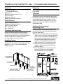
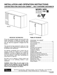
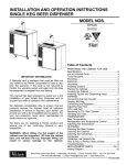
INSTALLATION AND OPERATION INSTRUCTIONS
CONCESSIONAIRE PORTABLE DISPENSERS
MODEL NOS.
DC Series
IMPORTANT INFORMATION
Complete the enclosed warranty card and mail to the
Perlick Corporation to register the warranty. If the
card is not returned, the warranty period will begin
from the date the equipment is shipped from the
factory.
This manual has been prepared to assist you in the
installation of your Concessionaire Dispenser and to
acquaint you with its operation and maintenance.
We dedicate considerable time to ensure that our
products provide the highest level of customer
satisfaction. If service is required, your dealer can
provide you with a list of qualified service agents. For
your own protection, never return merchandise for
credit without our approval.
We thank you for selecting a Perlick product and
assure you of our continuing interest in your
satisfaction.
WARNING: When lifting, the full weight of the
cabinet must be supported. Lift from the cabinet
base and not from the top. Improper lifting can
result in severe damage to the cabinet.
Table of Contents
PREPARING THE CABINET FOR USE
Specifications.........................................................2
List of Included Parts.............................................3
Tools Required.......................................................3
Plumbing................................................................3
Electrical ................................................................3
Installing Casters ...................................................3
TAPPING
Connecting the Keg Coupler .................................4
Tapping the Keg.....................................................4
Connecting the Regulator......................................5
Adjusting Gas Flow................................................5
CO2 Leak Test .......................................................5
Replacing a CO2 Gas Cylinder..............................5
Handling CO2 Gas .................................................5
TEMPERATURE
Beer Temperature ..................................................6
CLEANING
Cleaning the Beer Lines ........................................7
Cleaning the Cabinet .............................................7
GENERAL INFORMATION
How to Pour a Perfect Glass of Beer ....................8
Troubleshooting .....................................................9
Beer Facts .............................................................9
REPLACEMENT PARTS ................................10-11
Wiring Diagram....................................................12
8300 West Good Hope Road • Milwaukee, WI 53223 • Phone 414-353-7060 • Fax 414-353-7069
Toll Free 800-558-5592 • E-Mail: [email protected] • www.Perlick.com
Form No. Z2060A
Rev. 12.05.03
Installation and Operating Instructions
Sizes and Specifications, Concessionaire Dispensers
MODEL NOS.
DC2KP
DC3KP
DC4KP
KEG CAPACITY
2 Keg
3 Keg
4 Keg
DIMENSIONS Length Ins. (mm)
72” (1829)
84” (2134)
96” (2438)
CABINET
Depth Ins. (mm)
241/8” (613)
241/8” (613)
241/8” (613)
Height Ins. (mm)
341/2” (876)
341/2” (876)
341/2” (876)
NO. OF DISPENSING HEADS
1
1
2
NO. FAUCETS
2
2
2
1/4
1/3
1/3
CONDENSER UNIT H.P.
RUNNING LOAD - AMPS
5.9
7.5
7.5
SHIP WT lbs. (kg)
445 (202)
505 (229)
545 (247)
INTERIOR
Fourteen gauge stainless steel sills are reinforced with a 12 gauge angle bracket that extends from one
end of the insulated base to the other. The floor pan is 20 gauge, type 304 stainless steel. The walls and
ceiling are 20 gauge galvanized steel.
EXTERIOR
The top is 20 gauge stainless steel. Bottom is 20 gauge stainless steel. Doors, front, back and sides are
20 gauge black powder coated steel.
STORAGE COMPARTMENTS
Side compartment houses a four gallon stainless steel drainer overflow tank, two drain valves with garden
hose fittings for cabinet floor drain and overflow tank, and 20 lb. CO2 drum holder. Front compartment
provides storage for cups or other non-refrigerated items.
REFRIGERATION
R-134a capillary tube-type. Aluminum fin and copper tube evaporator coil. Forced air into dispensing head.
Adjustable temperature control. Self-defrosting. Pull-out condensing unit for service and cleaning.
VENTILATION
Front ventilated.
ELECTRICAL
115 Volt, 60 Hz., 1 Phase AC. Furnished with three prong, six foot rubber cord.
Contact Perlick for other voltage/frequency requirements.
PLUMBING
None required. Condensate evaporates automatically.
INSULATION
Foamed-in-place polyurethane; 2” walls, 11/2” top and floor.
OPTIONAL ACCESSORIES
• Optional Dispensing Heads
• Shelf Kit
• Faucet Locks
• Keg Couplers
• Regulators
Perlick is committed to continuous improvement. Therefore, we reserve the right to change specifications without prior notice.
Form No. Z2060A
Rev. 12.05.03
2
Preparing the Cabinet for Use – Concessionaire Dispensers
Parts List
■
■
■
■
■
■
■
Plumbing
Faucet Standard.
Faucet Head Assembly
Caster Set.
Black Connector Hose 3⁄16” x 3’.
5
⁄16” Air Hose.
Spanner Wrench.
Bag of Miscellaneous Parts.
None required. Garden hose connections for dumping
liquid wastes.
Electrical
The cabinet must be connected to a separately
fused power source (see electrical specification
plate) and grounded in accordance with National
and Local Electrical Codes. Caution: Do not
attempt to operate the equipment on any other
power source than that listed on the Electrical
Specification plate.
Tools Required
■
■
■
■
■
#2 Phillips Screwdriver.
Spanner Wrench (included).
#10 Crescent Wrench.
9/ 16” Allen Wrench.
3/ 8” Nut driver.
Installing the Faucet and
Dispensing Head
Before you begin: Wash dispensing head and
faucet. Flush beer, dispensing head and faucet
lines with fresh water.
■ Apply RTV around the base of the dispensing
head to seal it to the top. Align the dispensing
head over the five holes on the cabinet top
and use the five stainless steel #10-32 x 13⁄4”
Phillips pan head stainless steel machine
screws to secure standard to cabinet top.
Wipe off excess RTV to complete the seal.
■ Attach faucet to standard using spanner
wrench to tighten coupling. Attach faucet
handle to faucet.
■ Insert flexible plastic air hose six to seven
inches into bottom of faucet standard.
Secure hose with tie wrap (supplied).
Uncrating and Inspection
Remove all crating material before operating.
Carefully inspect cabinet for hidden damage. If
damage is discovered, file your claim immediately
with the transportation company. Perlick is
not responsible for damage in transit.
Installing Casters
IMPORTANT: Attach casters to the cabinet bottom
so that caster is centered over cabinet seam. Use
supplied 1/ 4”- 20 x 3/ 4” hex head self-tapping
machine screws.
CASTER MOUNTING
PLATE MUST
STRADDLE SEAM
COMPRESSOR
HOUSING
SCREWS
CENTER CASTERS
REQUIRED ON DC4KP
(4 KEG CONCESSIONAIRE)
DRY
STORAGE
COMPARTMENT
CASTER MOUNTING
PLATE MUST
STRADDLE SEAM
Perlick is committed to continuous improvement. Therefore, we reserve the right to change specifications without prior notice.
3
Form No. Z2060A
Rev. 12.05.03
Installation and Tapping – Concessionaire Dispensers
Connecting the Keg Coupler
(when Supplied by Perlick)
■
■
■
■
Tapping a Single Valve Keg (Sankey):
Place one brown leather washer into black beer
line connector hose on hex nut side. Screw
connector to stainless steel beverage line on
faucet standard. Tighten with a wrench, but do
not over tighten.
Make sure lever handle on the keg coupler is in
the UP (untapped) position. Place one brown
leather washer into wing nut end of black beer
line connector hose and thread onto top of keg
coupler. Hand tighten.
Place clamp on one end of red air line. Push
end over air valve located inside cabinet.
Tighten clamp with screwdriver. Turn shut-off
valve to OFF (horizontal) position.
Place clamp on the other end of red air line and
push over tailpiece on coupler. Tighten clamp
with screwdriver.
CAUTION: Do not use keg coupler as a
handle to lift keg.
Step 1
Single Valve Keg Coupler
OUT
Step 3
DOWN
Step 2
1/4
TURN
■
■
■
■
Be sure beer faucet is in closed position.
Align keg lugs with lug openings on bottom
of coupler.
Turn clockwise 1⁄4 turn. Pull handle out and
down. Keg is now tapped.
Open shut-off valve on air divider located inside
of the cabinet.
Important: Be sure to close this valve
when untapping keg.
Perlick is committed to continuous improvement. Therefore, we reserve the right to change specifications without prior notice.
Form No. Z2060A
Rev. 12.05.03
4
Installation and Tapping – Concessionaire Dispensers
■
Connecting the Regulator to the
CO2 Cylinder
■
■
■
■
Remove blue plug from regulator fitting.
(Note: Do not remove the carbonic washer).
Screw regulator onto gas cylinder valve. Tighten
with wrench until vertically straight. Be sure that
shut-off valve (black lever) on regulator is in
the OFF (horizontal) position.
Place a screw clamp over end of red air line
and push onto regulator tailpiece. Tighten clamp
with a screwdriver.
■
■
Unscrew regulator from cylinder fitting.
Replace carbonic washer (Part No. 157F2P),
if needed and reattach regulator to filled
cylinder.
Turn CO2 hand valve counterclockwise until
fully open. Turn regulator shut-off valve to
open position.
Adjust CO2 gas flow as required, turning
clock wise for higher pressure.
Proper CO2 Handling
ALWAYS...
CO2
PRESSURE
GAUGE
REGULATOR
FITTING
■
HAND
VALVE
■
20
30
40
PERLICK
50
10
PSI
0
60
■
■
■
CO2
GAS
DRUM
■
FITTING FOR
RED AIR HOSE
■
SHUT-OFF VALVE
(BLACK LEVER IN
CLOSED POSITION)
REGULATOR
ADJUSTING
SCREW
■
Connect a regulator (reducing valve) to
CO2 cylinder.
Secure cylinder in upright position whether in
storage or in use.
Keep cylinder away from heat. Rupture disc
vents at 122° F. maximum.
Ventilate room after high pressure gas leakage.
Check the last DOT test date on cylinder neck
before filling. If more than five years old, the
cylinder must be retested to DOT specifications.
Be sure CO2 cylinder outlet fitting is free of dust
or dirt before attaching regulator.
Store CO2 cylinder and regulator assembly
upright.
Allow only properly trained and experienced
personnel to handle high pressure gas.
NEVER...
Adjusting the CO2 Gas Flow
■
■
■
■
■
Connect cylinder directly to a keg without a
regulator (reducing valve).
■ Drop or throw regulator or CO2 cylinder.
■ Transport CO2 cylinder in a closed vehicle.
■ Apply oil to a regulator.
■ Shut off CO2 cylinder when not in use. You will
not save gas by doing so!
■ Allow untrained, inexperienced personnel to
handle high pressure gas.
Failure to heed this warning could result in
personal injury or death.
Turn regulator adjusting screw counterclockwise
until it turns freely.
Turn hand valve counterclockwise on CO2
cylinder to the fully open position.
Turn regulator adjusting screw clockwise until
desired pressure is reached (approximately
12-15 lbs.). Tighten stop nut on adjusting screw.
Open shut-off valve on bottom of regulator.
CO2 Leak Test
Dilute a small amount of liquid dishwashing soap
and rub the soapy mixture around each connection.
If bubbles appear, tighten connection.
WARNING/SAFETY INSTRUCTIONS
Beverage systems pressurized with carbon dioxide or
nitrogen must be equipped
with two safety relief
valves; one at the cylinder
regulator and the other in
the gas line upstream on
the product tanks.
Replacing CO2 Gas Cylinder
■
Turn CO2 hand valve clockwise until seated and
close shut-off valve on regulator.
Perlick is committed to continuous improvement. Therefore, we reserve the right to change specifications without prior notice.
5
Form No. Z2060A
Rev. 12.05.03
Draft Beer Information – Concessionaire Dispensers
Temperature
One of the most common causes of dispensing
problems is improper temperature. Draft beer
should be stored at a temperature between 32° and
38°. At warmer temperatures, beer will foam.
At temperatures lower than 30° F., beer will freeze.
When beer freezes, the alcohol in the beer may
separate and cause the beer to be cloudy with an
“off” taste.
Refrigeration and Temperature Control
Adjusting the temperature
The Direct Draw Dispenser is equipped with a
heavy-duty refrigeration system designed to
automatically maintain a storage temperature of
36-41 degrees F. The control is factory set at 38
degrees F.
The temperature control is inside the cabinet on
the right-hand side of the evaporator fan panel
assembly. You will need a screwdriver to turn the
adjusting screw. Make small adjustments until the
desired temperature is achieved.
■ Colder Temperatures:
Turn the adjusting screw clockwise (to the right).
■ Warmer Temperatures:
Turn the adjusting screw counterclockwise
(to the left).
The condenser fan motor turns off and on with the
condensing unit. The evaporator fan motor runs
continuously. The fan motors are lifetime lubricated
and will require no oiling.
NOTE:
Cabinet Temperatures lower than 34° will not allow
for proper defrosting of the evaporator coil. If
defrosting is necessary, turn the control knob to the
OFF position until coil is defrosted.
Perlick is committed to continuous improvement. Therefore, we reserve the right to change specifications without prior notice.
Form No. Z2060A
Rev. 12.05.03
6
Cleaning the Beer System – Concessionaire Dispensers
■
The entire beer system, to include the faucet, flexible
beer line and tapping devices must be cleaned at
regular intervals. We recommend flushing the entire
system with fresh water immediately after a keg has
been emptied. Once each month the system should
be cleaned chemically.
It is recommended that you purchase Perlick’s
Pump Type Sterilizer, as shown below. It is
equipped with an adapter that attaches directly to
the faucet shank in lieu of the faucet. It is also
available with a slip coupling for those who choose
to clean their faucets in place.
Part Nos.
887P
887PSC
848A33
Description
1
⁄2 Gallon sterilizer w/faucet coupling.
1
⁄2 Gallon sterilizer w/slip coupling.
33 oz. Liquid Alkaline cleaner.
Beer Stone:
All beer contains calcium which is present from
the grains used in the brewing process. it is an
important natural material in draft systems in
that as it oxidizes it coats the internal parts of
the beer lines and equipment. This thin coat of
beer stone helps prevent the beer from picking
up strong metallic or plastic flavors as it flows
through the system. The beer stone will
continue to build if the system is not cleaned
properly or regularly and can cause drawing
problems if it begins to flake off. Beer stone is
present if one can see a brownish color on the
faucet or inner wall of the beer line, or tobaccolike flakes in the beer.
Cleaning the Cabinet
Cleaning the draft beer system
will help to eliminate the build-up
of the following materials:
■ Bacteria:
Beer is an excellent food for
bacteria (none of which is
harmful). Proper conditions
may begin the growth of
bacteria in draft beer and on
the beer faucet. By regular
cleaning, we prevent this
bacterial buildup and
maintain the quality of the
No. 887P
draft beer. Greenish or yellowish colored material on the faucet may indicate
bacterial growth.
■ Yeast:
All domestic draft beers contain a small amount
of yeast which remains in the beer from the
fermentation process. When the temperature of
draft beer exceeds 50° a process of secondary
fermentation may take place. The beer faucet
may exhibit a white colored substance (yeast
build up) if not cleaned on a regular basis.
Use a mild detergent and water to clean the inside
and outside of the cabinet. Dry thoroughly. Never
use a scouring pad or abrasive cleanser.
NOTE: An industrial strength, commercial cleaner
can be used to clean the outside of painted
cabinets.
Cleaning the Condenser
Use a long handled, stiff brush to clean the dirt from
the front surface of the condenser. Keeping the
condenser free from dust and dirt will ensure efficient operation.
CAUTION: Do not bend the fins while brushing the
front of the condenser.
Perlick is committed to continuous improvement. Therefore, we reserve the right to change specifications without prior notice.
7
Form No. Z2060A
Rev. 12.05.03
Pouring a Perfect Glass of Beer – Concessionaire Dispensers
STEP 1
➠
Start with a clean glass.
Place the glass at a
45° angle, one inch
below faucet. Do not
let the glass touch the
faucet. Open the faucet
all the way.
STEP 2
➠
After the glass has
reached half full,
gradually bring the
glass to the upright
position
STEP 3
➠
Let the remaining beer
run straight down the
middle of the glass.
This ensures proper
release of CO2 by
producing a 3⁄4” to 1”
foam head.
STEP 4
➠
Close the faucet quickly
and completely.
Perlick is committed to continuous improvement. Therefore, we reserve the right to change specifications without prior notice.
Form No. Z2060A
Rev. 12.05.03
8
Trouble Shooting – Concessionaire Dispensers
Beer Service Problems
■
■ Cloudy Beer:
Beer in glass appears hazy, not clear.
CAUSES:
■ Dirty glass.
■ Dirty faucet or beer line.
■ Frozen or nearly frozen beer.
■ Old beer.
■ Beer that has not been refrigerated for a
long period of time.
Wild Beer:
Dispensed beer has either too much foam or
is all foam.
CAUSES:
■ Beer has been dispensed improperly.
Solution: See pouring instructions
on page 8.
■ Regulator pressure is set too high.
■ Warm keg temperature.
Solution: Keg must be colder than
40°. Target temperature is between
36° and 38° F.
■ Cabinet door is opened and closed
frequently and temperature is warmer
than 38° F.
Solution: Adjust temperature to between
36° and 38° F.
■ Kinks, dents or obstructions in the line.
■ Using oddly shaped glasses. Frosted,
waxed or styrofoam containers may
cause foaming.
■ Dispenser has been turned off for a
long period of time.
■ Faucet is bad, dirty or in a worn condition.
■ Regulator malfunction.
Beer and CO2 Facts
Keg
Size
Quarter
Half
■
■
■
■
■
No. of
Gallons
No. of
Oz.
No. of
Cases
73⁄4
151⁄2
992
1,984
3.445
6.889
No. of
Full Keg
12Oz.
Weight
Servings
105
87 lbs.
210
161 lbs.
Beer foam is 25% liquid beer and 75% CO2
gas. Don’t waste it!
Most people prefer beer stored at 38° F.
Beer lines and faucets require regular cleaning
(see cleaning instructions on page 7).
A fully-charged 4.2 lb. CO2 cylinder will
dispense approximately 51⁄2 to 61⁄2 half barrels.
CO2 gas gives beer its sparkling effervescence.
It also gives beer its creamy head of foam.
■ Flat Beer:
Foamy head disappears quickly; beer lacks
brewery fresh flavor.
CAUSES:
■ Dirty glassware.
■ CO2 pressure is too low, due to leak or
pressure setting.
■ CO2 is turned off at night.
■ Cooler is too cold.
■ CO2 leak or defective (sticking)
check valve.
■ Sluggish CO2 regulator.
Perlick is committed to continuous improvement. Therefore, we reserve the right to change specifications without prior notice.
9
Form No. Z2060A
Rev. 12.05.03
Replacement Parts – Concessionaire Dispensers
MODEL NOS.
All Models
Left hinged door assembly
Right hinged door assembly
Magnetic door gasket
Hinge set, left
Hinge set, right
Elbow-nylon 3⁄4” F.P.T. x 1⁄2” barb
1
⁄2” trans vinyl beverage tubing 8.7 ft.
Glass rack
Bulb clamp
Wiring harness
Fan motor
51/2” diameter fan blade
Fan guard assembly
Fan motor 1⁄3, 1⁄4 and 1⁄5 h.p.
Door locks
Door lock
Trim ring
Lock bracket
Waste tank assembly
3
⁄4” ball valve
3/4” adapter male hose x F.P.T.
Pocket pull flush handle
Dry storage door assembly
Door assembly
Magnetic catch
Shelf kit
Condensing units (2 door models)
1/ 4 h.p. condensing unit
115 volt, 60 hz.
Condensing unit (model UFI10HBX)
Compressor (model FFI10HBX)
Fan Motor Assembly
Condenser coil
Terminal board
Overload protector
Relay
Capacitor (282-339 MFD. 155V)
Coil assembly 2 door SC BB
Fin coil, evaporator
Two-way air distributor assembly
Condensing units (3 & 4 door models)
1/3 h.p. condensing unit 115 volt
Condensing unit (model UFI12HBX)
Compressor (model FFI12HBX)
Fan Motor Assembly
Condenser coil
Terminal board
Overload protector
Relay
Capacitor (378-454 MFD. 115V)
Coil assembly 3⁄4 door SC BB
Fin coil, evaporator
Shelf kit, center
Three-way air distributor assembly
Four-way air distributor assembly
DC2KP
DC3KP
DC4KP
64357SLBL
64357SRBL
62085-1
63407L
63407R
57736-1
1390TR
C24639-1
C6634
61186-1
C15239A
57699
C25395
57513
61259
61260
57811
57781-1
62287
57793
57800
57775
62278
62279
C15381
57928
64357SLBL
64357SRBL
62085-1
63407L
63407R
57736-1
1390TR
C24639-1
C6634
61186-1
C15239A
57699
C25395
57513
61259
61260
57811
57781-1
62287
57793
57800
57775
62278
62279
C15381
57928
64357SLBL
64357SRBL
62085-1
63407L
63407R
57736-1
1390TR
C24639-1
C6634
61186-1
C15239A
57699
C25395
57513
61259
61260
57811
57781-1
62287
57793
57800
57775
62278
62279
C15381
57928
C22647
N/A
N/A
515301063
513200314
215315009
15352019
219101538
MRT20AGK5590
21351619
13556529
62210A1*
C17511-1
C18942
N/A
N/A
N/A
N/A
N/A
N/A
N/A
N/A
N/A
N/A
N/A
N/A
N/A
N/A
N/A
N/A
N/A
N/A
N/A
N/A
N/A
N/A
N/A
N/A
N/A
N/A
N/A
N/A
N/A
N/A
N/A
N/A
N/A
N/A
N/A
N/A
C22646
515301062
513200003
215315009
15352019
219101538
MRT22AFZ5590
21351619
13556532
62210A2*
C17511-2
57929
C18943
C18944
C22646
515301062
513200003
215315009
15352019
219101538
MRT22AFZ5590
21351619
13556532
62210A2*
C17511-2
57929
C18943
C18944
Perlick is committed to continuous improvement. Therefore, we reserve the right to change specifications without prior notice.
Form No. Z2060A
Rev. 12.05.03
10
Replacement Parts – Concessionaire Dispensers
For Single Valve Keg Coupler (Series D)
Item
Part
No.
No.
Description
1 ............26000D ..............Single valve keg coupler
2 ............C14316 ..............“O” ring
3...........31080-2P.............Ball check
4...........31089-2P.............“O” ring (3 per assembly)
5...........31088-2P.............Bottom seal washer
6...........31087-2P.............Probe washer domestic
7............157R2P ..............Coupling Gasket
8...........23682-2P.............Check valve
1
2
3
4
7
8
5
6
Miscellaneous
Part
No.
Description
157L2P................Beer line connector gasket
57F2P .................CO2 tank washer
1392R .................Red air hose
529 ......................Beer hose
2928D .................Twin gauge CO2 regulator
Perlick is committed to continuous improvement. Therefore, we reserve the right to change specifications without prior notice.
11
Form No. Z2060A
Rev. 12.05.03
Wiring Diagram – Concessionaire Dispensers
8300 West Good Hope Road • Milwaukee, WI 53223 • Phone 414-353-7060 • Fax 414-353-7069
Toll Free 800-558-5592 • E-Mail: [email protected] • www.Perlick.com
Perlick is committed to continuous improvement. Therefore, we reserve the right to change specifications without prior notice.
12
Form No. Z2060A
Rev. 12.05.03