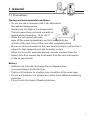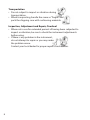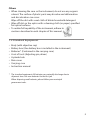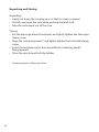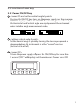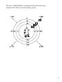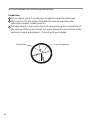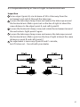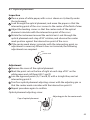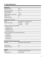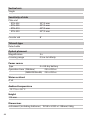
1
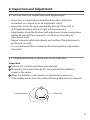
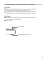
Total Construction Solutions
Electronic
Instruction manual
Theodolites
ETH-302
2 sec. Angle Accuracy
Detachable Tribrach
ETH-305
5 sec. Angle Accuracy
Detachable Tribrach
ETH-310
10 sec. Angle Accuracy
Detachable Tribrach
ETH-320
20 sec. Angle Accuracy
Detachable Tribrach
PENTAX Industrial Instruments Co., Ltd.
2-5-2 Higashi-Oizumi / Nerima-ku, Tokyo 178-0063, Japan
Tel. +81-3-5905-1222 / Fax +81-3-5905-1225
E-mail: [email protected]
Safety Precautions (must be followed)
The following items are intended to prevent possible injury to the user or
other people and/or damage to the instrument before it occurs.
These safety precautions are important to the safe operation of this
product and should be observed at all times.
•Distinctive Displays
The following displays are used to distinguish precautions by the
degree of injury of damage that may result if the precaution is ignored.
WARNING
Items indicated by this display are precautions which if ignored could
result in death or serious injury.
CAUTION
•
•
Items indicated by this display are precautions which if ignored may
result injury or material damage.
Here ”injury” refers to injuries such as cuts, burns or electric shock
the treatment of which will not likely require hospitalization or
long-term attention.
”Material damage” refers to the damage to facilities, buildings,
acquired data, etc.
WARNING
•
•
Never look at the sun through the telescope as this may result in loss of
sight.
Do not use at a place near flammable materials as there will be a risk of
fire or injury by explosion.
3
CAUTION
•
•
•
•
•
•
•
•
•
Secure the handle of main unit with the handle locking screws.
Failure to properly secure the handle could result in the main unit
detaching from the handle while being carried, causing injury.
Do not use the carrying case as a footstool as it is slippery and
unstable and may cause you to fall, resulting in possible injury.
When mounting the instrument to the tripod, tighten the center
screw securely. Failure to tighten the screw properly could result
in the instrument falling off the tripod causing injury.
Securely tighten the leg fixing screws of the tripod. A person
could be injured by the tripod shoes on an extending leg due
to a loose screw.
Do not carry a tripod with the metal shoe pointing toward another
person as the person may be injured if they strike them.
Make sure that your hands and feet are not in the vicinity of
the tripod legs when setting up the tripod, or a hand or foot stab
would occur.
Do not wield or throw the plumb bob. A person could be
injured if struck.
If a battery box or a battery is gets wet by water, wipe off the
water and dry immediately.
When a battery box is removed from the unit, power must be off.
If the battery box is removed with power on, it will cause trouble.
Electro-Magnetic Compatibility(EMC)
This instrument complies with the protection requirement for
residential and commercial areas.
If this instrument is used close to industrial areas or transmitters,
the equipment can be influenced by electromagnetic fields.
4
CONTENTS
• 1.
1.1
1.2
1.3
1.4
• 2.
2.1
2.2
2.3
2.3.1
2.3.2
2.3.3
2.3.4
2.3.5
2.3.6
2.4
2.4.1
• 3.
3.1
3.2
3.3
3.4
3.5
3.6
• 4.
4.1
4.2
4.3
4.4
4.5
4.6
General
Precautions
Standard equipment
Names of Parts
Preparation of power
Key Operations and Display
Display
Keyboard
Function of each key
Power on-off key
V/% key
Hold key
0 set key
R/L key
Illumination key
Other functions
Remaining battery indicator
Special Key Operations
Setting of vertical angle
Setting of 90°buzzer
Setting of correction of vertical angle
Setting of angle measurement
Setting of automatic power-off function
Setting of Angle unit
Preparation for Surveying
Setting up the instrument
Leveling with the circular vial
Leveling with the plate vial
Centering with the optical plummet
Eyepiece adjustment
Object sighting
7
14
22
28
5
CONTENTS
• 5.
5.1
5.2
5.3
• 6.
6.1
6.2
6.3
6.4
6.5
6.6
6.7
• 7.
7.1
• 8.
6
Measurement
Horizontal angle measurement (right)
Horizontal angle measurement (left)
Vertical angle measurement
Inspection and Adjustment
Instructions on inspection and adjustment
Perpendicularity of plate vial to vertical axis
Perpendicularity of circular vial to vertical axis
Inclination of reticule graduations
Perpendicularity of line of sight to horizontal axis
Difference of the vertical angle
Optical plummet
Optional Accessories
Diagonal eyepiece
Specifications
34
37
44
45
1. General
1.1 Precautions
Storing and environmental conditions
• Do not use the instrument until it has adjusted to
the ambient temperature.
• Avoid using at a high or low temperature.
The instrument may not work normally at
temperatures exceeding –10 or +50˚C.
• When the instrument gets wet,
wipe off the water immediately and let it completely dry
outside of the case. Store in the case after completely dried.
• Be sure to store instrument in the case. Avoid storing in a place that is
subject to high temperature, high humidity, or dust.
• When not in use for extended periods, remove a battery from the
battery box. Also remove the instrument from the case and expose
to the air periodically.
Battery
• Batteries can naturally discharge due to shipment time.
Use new batteries for the first job.
• The four (4) batteries, in a battery box, should be of the same type.
• Do not use batteries, in a battery box, which have different remaining
capacities.
• Do not touch the liquid of leaking batteries.
7
Transportation
• Do not subject to impact or vibration during
transportation.
• When transporting, handle the same as ”fragile” and
pack the shipping case with cushioning materials.
Inspection, Adjustment and Repair, Overhaul
• When not in use for extended periods of having been subjected to
impact or vibration, be sure to check the instrument adjustments
before using.
• If there is any problem in the instrument,
do not attempt to repair or you may make
the problem worse.
Contact your local dealer for proper repair or instructions.
8
Others
• When cleaning the case or the instrument, do not use any organic
solvent. The surface of plastic parts may dissolve and deformation
and discoloration can occur.
Wipe off the dirt with a wet cloth of dilute household detergent
• Wipe off dirt on the optics with a cleaning cloth (or paper) specified
for optical surfaces.
• To realize full capability of the instrument, adhere to
cautions described in each chapter of this manual.
1.2 Standard Equipment
•
•
•
•
•
•
•
•
Body (with objective cap)
Battery box (One battery box is installed in the instrument)
Batteries* (Contained in the carrying case)
A set of tools (Adjusting pin, driver)
A plumb bob
Rain cover
Carrying case
Instruction manual
* The standard equipment AA batteries can naturally discharge due to
shipment time. Use new batteries for the first job.
When disposing used batteries, please follow your municipal
government rules.
9
Unpacking and Storing
Unpacking
• Gently set down the carrying case so that its cover is upward.
• Unlatch and open the case while pushing the latch lock.
• Take the instrument out of the case.
Storing
• Set the telescope almost horizontal, and lightly tighten the telescope
clamp screw.
• Align the containing marks*, and lightly tighten the horizontal clamp
screw.
• Insert the instrument into the case with the containing marks*
facing upward.
• Close the case lid and lock the latches.
* Containing mark = Yellow dot sticker
10
1.3 Names of Parts
Handle
Screw for handle
Collimator
Objective lens
Optical plummet
Instrument height mark
(215mm)
Leveling screw
Bottom plate
Tribrach locking lever
11
Eyepiece cap
Eyepiece lens
Battery box
Focusing knob
Telescope tangent screw
Plate vial
Telescope clamp screw
LCD panel
Horizontal clamp screw
Keyboard
Horizontal tangent screw
Circular vial
12
1.4 Preparation of Power
• Remove battery box from the unit by pushing the release button on
the top of the battery box. Remove the battery box cover.
• Insert four AA batteries into the battery box according to (+) and (-).
• Press the battery box to the leg by inserting the guide pin
to the guide groove.
• Confirm the correct work by pressing the power switch.
This instrument can operate using 1.2V AA rechargeable batteries.
• The four (4) batteries, in a battery box, should be of the same type.
Do not use batteries, in a battery box, which have different remaining
capacities.
• When a battery box or batteries are wet, wipe off the moisture
immediately and dry completely.
• When a battery box is removed from the unit, power must be off.
If the battery box is removed with power on, it will cause trouble.
13
2. Key Operations and Display
2.1 Display
Vertical angle
V=Zenith 0°, V%=Slope(VH=Horizontal 0°, Vc=Compass)
Horizontal angle Battery indicator:
(HR=right rotation horizontal angle, HL=left rotation horizontal angle)
2.2 Keyboard
[V/%] key
(Switches the display of vertical angle)
[R/L] key
(Set the horizontal angle right
and left rotation alternately)
[HOLD] key
(Pressing twice holds the horizontal
angle shown on the display)
[0SET] key
(Pressing twice resets the horizontal angle to 0°,00’,00”)
[
] Illumination key (Illuminate LCD panel and the telescope reticle)
[ON/OFF] key
14
(Turns the power on and off alternately)
2.3 Function of each key
2.3.1 Power [ON/OFF] key
1 <Power ON and set the vertical angle 0 point>
Pressing the ON/OFF key turns on the power supply and the message
”0 SET” is displayed. After the ”0 SET” of vertical angle is performed,
the Horizontal and Vertical angle are displayed and the instrument
enters into the angle measurement mode.
2
<Setting vertical angle 0 point>
Set the vertical angle 0 point by turning the telescope upward or
downward when the instrument is at the ”normal” position
(Vertical circle at left.)
3
<Power OFF>
To turn the power supply off, press the ON/OFF key for more than
1 second (”OFF” will display) and then release it. Power turns OFF.
15
2.3.2 [V/%] key
Pressing the V/% key will change the Vertical angle display to
V%(slope). (At the shipping, it is set at Zenith 0°)
By special key operation, horizontal 0° (VH) and Compass (Vc)
can be set.
(Factory default is Zenith 0°)
(Refer to 3.1 Setting of vertical angle.)
16
The error ”OVER RANGE” is displayed when the telescope
exceeds 45°(100%) in the V% display mode.
17
2.3.3 [HOLD] key
1 Press the [HOLD] key twice in succession to hold the displayed
horizontal angle and retain it. (Press once, the key buzzer will sound,
then press again during the sound.)
2 Press the key once more to release.
To prevent operation error, the buzzer sounds for three seconds
when the [HOLD] key is pressed.
HOLD is not initiated unless the key is pressed during
the buzzer sound.
18
2.3.4 [0SET] key
1 Press the [0SET] key twice in succession to reset the displayed
horizontal angle 0°,00’,00”. (Press once, the key buzzer will sound,
then press again during the sound.)
2 Press the key once more to release.
To prevent operation error, the buzzer sounds for three seconds when
the [OSET] key is pressed.
[OSET] is not initiated unless the key is pressed during the buzzer
sound.
19
2.3.5 [R/L] key
Press the [R/L] key to change from clockwise to counterclockwise
rotation. A clockwise or counterclockwise reading is alternately
displayed each time the key is pressed.
Count horizontal angle in a right
rotation direction (HR)
2 Counterclockwise horizontal angle Count horizontal angle in a left
rotation direction (HL)
If the power turns off during the counterclockwise mode, the display
returns to a clockwise horizontal angle display when power is turned on.
1
Clockwise horizontal angle
2.3.6 [Illumination key ]
Pressing the key, illuminates the LCD panel and telescope reticule.
The illumination is automatically turned off after five minutes.
Pressing the key, with illumination on, turns off the illumination.
20
2.4 Other Functions
2.4.1 Remaining battery indicator
The status of the remaining battery capacity is displayed with
” ” symbolizing the battery capacity.
Battery full - operating possible
Operation possible
Operation still possible
Get the battery ready for a stand by
Replace batteries
Automatic Power-off function
If there is no key operation for about 30 minutes, the power supply is
turned off automatically.
This function can be set to NIL by special key operation. (Refer to 3.5
Setting of automatic power off function.)
21
3. Special key operations
Special key operation enables selection of angle unit and
other such items.
22
1
Press [HOLD] key and [0SET] key at the same time
2
Press [ON/OFF] key
3
Release [ON/OFF] key
4
(No display or buzzer)
Release [HOLD] key and [0SET] key,
5
Following display appears:
Flow of setting display
Setting of vertical angle
Press [R/L] key
Setting of 90°buzzer
Press [R/L] key
Setting of correction of vertical angle
Press [R/L] key
Setting of angle display
Press [R/L] key
Setting of automatic power off function
Press [R/L] key
Setting of Angle unit
Previous items can be displayed by pressing the [HOLD] key.
23
3.1 Setting of Vertical Angle
Vertical angle setting display by special key operation
Zenith 0° (V)
Setting is switched by pressing [0SET] key
Horizontal angle 0°(VH)
Compass (Vc)
Store with [V/%] key when the setting is decided.
24
3.2 Setting of 90°buzzer
90°buzzer setting display by special key operation
No 90°buzzer
Setting is switched by pressing [0SET] key
With 90°buzzer
Store with [V/%] key when the setting decided.
3.3 Setting of correction of vertical angle
Correction of vertical angle setting display by special key operation
Setting is switched by pressing [0SET] key
Store with [V/%] key when the setting decided.
25
3.4 Setting of angle measurement
Angle setting display by special key operation
1
For models ETH-302/305
Setting is switched by pressing [0SET] key
Store with [V/%] key when the setting decided.
2
For models ETH-310
Setting is switched by pressing [0SET] key
Store with [V/%] key when the setting decided.
3
For ETH-320
Setting is switched by pressing [0SET] key
Store with [V/%] key when the setting decided.
26
3.5 Setting of automatic power off function
Automatic power off function setting display by special key operation
Automatic power off active
Setting is switched by pressing [0SET] key
Automatic power off inactive
Store with [V/%] key when the setting decided.
3.6 Setting of Angle unit
Setting is switched by pressing [0SET] key
You can Select DEG or DEC or GRD or MIL as the unit for angle.
Store with [V/%] key when the setting decide.
27
4. Preparation for Surveying
4.1 Setting up the instrument
1
2
3
Adjust the tripod legs so that a height suitable for surveying is
obtained when the instrument is set on the tripod.
A Set the tripod and fix the metal shoe firmly into the ground so that
the tripod head is as level as possible and centered above the station
point. If the tripod head is disturbed by the action of fixing the metal
shoe into the ground, correct the level by extending or retracting each
leg of the tripod.
Set the instrument on the tripod head; insert the tripod center screw
into the instrument bottom plate and tighten firmly.
Tripod head
Center screw
Tripod
28
Bottom plate
4.2 Leveling with the Circular level
After [4.1 Setting up the instrument] is completed, instrument must be
leveled using the circular vial.
1 By rotating any two leveling screws, position the bubble in the center
of the vial (See A.) (To adjust the screws at the same time, turn them in
opposite directions.)
2 Adjust the remaining leveling screw, and position the bubble in the
center of the circle (See B)
For the relation between the screw adjusting direction and bubble
moving direction, refer to the arrows of the following figures. Bubble will
move to the right in figure A, while in figure B it moves upward.
(A)
(B)
29
4.3 Leveling with the Plate level
After [4.2 Leveling with the circular vial] is completed, instrument must be
leveled with plate vial.
1 Place the plate vial in parallel with a line joining any two of the leveling
screws. By rotating two leveling screws in the opposite direction of
each other, position the bubble in the center of the vial (See A)
2 Rotate the plate vial through 90°, position the bubble in the center of
the vial by operating the remaining one leveling screw (See B)
3 Confirm if the bubble stays in the center by rotating the
instrument 180°.
If the bubble moves, repeat procedure 1 and 2 .
For the relationship between the screw adjusting direction and bubble
moving direction, refer to the arrows of following figures. Bubble will
move to the left in figure A, while in figure B moves upward.
When the bubble is not positioned in the center by repeating procedure
1 and 2 in procedure 4.2 , adjustment is required.
(Refer to [6.Inspection and Adjustment.])
Plate vial
(A)
30
(B)
4.4 Centering with the optical plummet
After [4.3 Leveling with the plate vials] is completed, the instrument must
be centered above the station point.
1
2
3
4
Focus the optical plummet reticule by rotating the optical plummet
eyepiece knob.
Focus the station point by rotating the optical plummet focusing knob.
Loosen the tripod center screw. Look through the optical plummet
eyepiece, and move the instrument bottom plate until the reticule
center coincides with the station point. (Take care not to rotate
the instrument)
Tighten the tripod center screw. Ascertain that the bubble stays
positioned in the center when rotating the plate vial position in steps
of 90°. If the bubble is not positioned in the center, adjust with the
leveling screws. (Refer to [4.3 Leveling with the plate vial]).
Even if the bubble is shifted by one graduation in 4 , deviation of
centering is just 0.3mm, at the instrument height of 1.4m, giving little
effect on the survey result.
Center mark
31
4.5 Eyepiece adjustment
After [4.4 Centering with the optical plummet] completed, focus the
telescope eyepiece on the telescope reticule.
1 Remove the telescope lens cap.
2 Point the telescope at a bright object.
3 Rotate the eyepiece completely counterclockwise.
4 Look through the eyepiece, and rotate the eyepiece clockwise until the
reticule appears at its maximum sharpness.
Reticule pattern
Vertical graduation
(single)
Optical axis
Horizontal graduation
(double)
Vertical graduation
(double)
At procedure 4 , keep your eye relaxed to prevent parallax and eye
fatigue. Parallax causes problems with object sighting.
(Refer to [4.6 Object sighting])
32
4.6 Object sighting
After [4.5 Eyepiece adjustment] is completed, sight the object.
1 Loosen the telescope clamp screw and horizontal clamp screw.
2 Point the telescope at the object using the collimator sight.
3 Tighten the telescope clamp screw and horizontal clamp screw.
4 Focus on the object by rotating the focusing ring, while looking
through the telescope.
5 Accurately align the reticule with the object, using each tangent
screw.
Collimator
Focusing ring
object
Telescope eyepiece
Horizontal clamp screw
Horizontal tangent screw
• In procedure 4 , focus on the object correctly so that the reticule
will not move in relationship to the object when you move your eye
slightly left and right, while looking through the eyepiece.
• Turn the focusing ring clockwise to focus on a near object.
Turn the focusing ring counterclockwise to focus on a far object.
• Two screws of the collimator are fixed and adjusted at the distributor
or the manufacturer. Do not move them arbitrarily.
33
5. Measurement
5.1 Horizontal angle measurement (right)
1
2
3
4
5
Level the instrument, and after power on set the vertical angle 0 point.
Sight the first object using the horizontal clamp and tangent screw as
well as the telescope clamp and tangent screw.
Press [0SET] twice to set the horizontal angle to 0°,00’,00”
Sight the second object using the horizontal clamp and tangent screw
as well as the telescope clamp and tangent screw.
Read the displayed value (α).
First Object: Zero Setting (0 °00’ 00”)
Second Object (34 °47’ 20”)
Horizontal Angle (α) = 34 °47’ 20”
First object
Second object
34
5.2 Horizontal angle measurement (left)
1
2
3
Level the instrument, and after the power on set
the vertical angle 0 point.
Sight the first object using the horizontal clamp and tangent screw as
well as screw as well as the telescope clamp and tangent screw.
Press the [R/L] key to switch the horizontal angle display to
counterclockwise reading (HL).
Subsequent operation will be done as in [5.1 Horizontal angle
measurement (right), but the order of collimation is reversed.
To switch the mode back to ”right”, press the [R/L] key again.
• If the power turns off during the counterclockwise mode, the display
returns to a clockwise horizontal angle display when power is
turned on.
35
5.3 Vertical angle measurement
Level the instrument, turn the power on and set
the vertical angle 0 point.
Sight the object A using the horizontal clamp and tangent screws as well
as the telescope clamp and tangent screws.
Read the displayed value ( ).
• The vertical angle mode can be changed to slope percent display
(V%) by pressing [V%] key.
Also, horizontal 0°(VH) and compass (Vc) can be set using special
key operation.
(Factory setting is Zenith 0°)
(Refer to 3.1 Setting of vertical angle)
Vertical angle (θ) = 86 °24’ 40”
Press the [V/%] key to view the Vv and V%.
Vertical angle 0 point
Object
Horizontal angle
36
6. Inspection and Adjustment
6.1 Instructions on inspection and adjustment
• Inspection and adjustment should be done after setting the
instrument on a tripod or on an adjustment stand.
• Inspection should be done sequentially from [6.2 Plate vial] to
[6.5 Perpendicularity of line of sight to horizontal axis]
• Adjustments should be finished with adjustment screws having been
tightened and with firm torque. Do not finish by loosening an
adjustment screw.
• Repeat inspection after adjustment and confirm if the adjustment is
performed correctly.
• It is recommended that a trained professional perform adjustments,
if possible.
6.2 Perpendicularity of plate vial to vertical axis
Inspection
1 Perform [4.3 Leveling with the horizontal vial]
2 Rotate the instrument through 90° and confirm if the bubble is
always in the center.
3 When the bubble is in the center, no adjustment is necessary.
If the bubble moves from the center, following adjustment is required.
Leveling screw
Plate vial
37
Adjustment
1 Center the plate vial bubble.
2 Rotate the instrument 180°, move the bubble half way back to
the center by operating a leveling screw which is located parallel
with the plate vial.
3 Rotate the vial adjusting screw with the adjusting pin and position
the bubble in the center.
4 Repeat procedure again to confirm.
38
6.3 Perpendicularity of circular vial to vertical axis
Inspection
1 Confirm if the bubble of the circular vial is in the center after
the inspection and adjustment of [6.2 Plate vial].
2 No adjustment is necessary if the bubble of the circular vial is
in the center but if not, the following adjustment is required.
Adjustment
1 Move bubble to the center by rotating the bubble adjusting
screws, using the adjusting pin.
2 Inspect again.
Circular vial
Bubble adjusting screws
39
6.4 Inclination of reticule graduations
Inspection
1 Set an object point A on the line of sight through the telescope.
2 Move point A to the edge of the field of view by adjusting the
telescope tangent screw (point A’).
3 No adjustment is necessary if point A moves along the vertical line of
the reticule. If the point A does not move along the vertical line of the
reticule, it needs adjustment - Consult with your dealer.
Line of sight axis
Vertical line
A'
40
6.5 Perpendicularity of line of sight to horizontal axis
Inspection
1 Set an object (point A) at a distance of 30 to 50m away from the
instrument and sight it through the telescope.
2 Loosen the telescope clamp screw and reverse the telescope around
the horizontal axis. Mark a point set on the line of sight at about the
same distance to the object point A, and call it point B.
3 Loosen the horizontal clamp screw, and rotate the instrument around
the vertical axis. Sight point A again.
4 Loosen the telescope clamp screw, and reverse the telescope around
the horizontal axis. Mark a point on the line of sight at about the same
distance as point B, and call it point C.
5 No adjustment is necessary if point B and C coincide,
but if it does not - Consult with your dealer.
41
6.6 Difference of the vertical angle
Inspection
1 Set the vertical angle in Zenith 0° mode
2 Sight an object (Point P) with the telescope and read the vertical
angle (V correct).
3 Reverse the telescope and rotate the alidade.
4 Sight point P again in the reverse position and
read the vertical angle (V reverse).
5 At this time, when (V correct + V reverse - 360°)/2 is less than 15”,
it is within tolerance. If it shows a larger value,
it needs adjustment - Consult your dealer.
42
6.7 Optical plummet
Inspection
1 Place a piece of white paper, with a cross drawn on it, directly under
the instrument.
2 Look through the optical plummet, and move the paper so that the
intersecting point of the cross comes to the center of the field of view.
3 Adjust the leveling screws so that the center mark of the optical
plummet coincides with the intersection point of the cross.
4 Rotate the instrument around the vertical axis. Look through the
optical plummet each step of 90° rotation, and observe the center
mark position against the intersection point of the cross.
5 If the center mark always coincides with the intersection point, no
adjustment is necessary. When it does not coincide, the following
adjustments are required.
Point
Center mark
Adjustment
1 Remove the cover of the optical plummet.
2 Mark the point set on the line of sight at each step of 90° on the
white paper and call them A,B, C and D.
3 Join the opposed points (A, C and B, D) with a straight line, and set
intersecting point 0.
4 Turn four optical plummet adjusting screws with the adjusting pin so
that the center mark coincides with the intersection point 0.
5 Repeat procedure again to confirm.
Optical plummet adjusting screw
Adjusting pin for the center mark
Cap of optical plummet
43
7. Optional Accessories
7.1 Diagonal Eyepiece (SB14)
The Diagonal eyepiece can be attached to the telescope for convenience
in observing the zenith or when in confined spaces.
<Installation>
1 Turn the telescope eyepiece ring counterclockwise to remove
the eyepiece.
Be sure to hold the eyepiece, securely, so that you do not drop it.
Attach the diagonal eyepiece to the telescope by reversing
the procedure.
The diagonal eyepiece can be rotated through 360°.
When sighting through the telescope with the diagonal eyepiece
attached, the reticule may be seen deflected vertically or horizontally,
but this has no influence upon accuracy.
44
8. Specifications
Telescope
Magnification
Effective aperture
Resolving power
Field of view
Minimum focus distance
Stadia ratio
Stadia constant
30 X
45 mm
3”
1° 30’
1.35 m
100
0
Angle Measurement
Type
Detection mode
Incremental rotary encoder
V. angle:
Single
H. angle:
Dual
Minimum Display (Selectable)
ETH-302 1”/5”
ETH-305 1”/5”
ETH-310 5”/10”
ETH-320 10”/20”
Accuracy (DIN18723, Standard deviation)
ETH-302 2”
ETH-305 5”
ETH-310 10”
ETH-320 20”
Vertical Angle Compensation
Method
Automatic compensation
Stadia Ratio
Stadia Constant
100
0
Display
Type
Display panel
Dot matrix LCD/Two lines
Dual display
45
Vertical axis
Single
Sensitivity of vials
Plate vial
ETH-302
ETH-305
ETH-310
ETH-320
30”/2 mm
30”/2 mm
40”/2 mm
40”/2 mm
Circular vial
8’
Tribrach type
Detachable
Optical plummet
Magnification
Focusing range
3x
0.5 m to Infinity
Power source
Type
4 x AA dry battery
Operation time (Alkaline)
25 to 28 hrs.
(NiMH2300mAh) 25 to 28 hrs.
Water resistant
IP x4
Ambient temperature
- 10 °C to + 50 °C
Height
215 mm
Dimensions
Instrument (including batteries) W168 x H330 x L158mm/4.6kg
46
PENTAX
PENT
X Industrial
Industrial Instrumen
Instruments
ts Co.,
C Lt
Ltd.
2-5-2 Higashi-Oizumi
Nerima-ku, Tokyo 178-0063, Japan
PENTAX Industrial
Tel.: Instruments
+81-3-5905-1222Co., Ltd.
Fax: + 81-3-5905-1225
E-mail: [email protected]
PENTAX Industrial Instruments C
PENTAX Industrial Instrum
PENTAX Industrial In
PENTAX Industria
PENTAX Indust
Printed in Belgium
certified
The CE marking assures that
this product complies with
the requirements of the EC
directive for safety.
Member symbol of the Japan Surveying
Instruments Manufacturers’ Association
representing the high quality surveying
products.