1
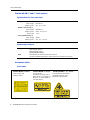
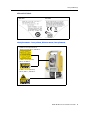
USER GUIDE Trimble M3 DR Series Total Station ® USER GUIDE ® Trimble M3 DR Series Total Station Trimble M3 DR 1” Trimble M3 DR 2” Trimble M3 DR 3” Trimble M3 DR 5” Version 1.00 Revision D February 2013 F Contact Information Trimble Navigation Limited Engineering and Construction Division 5475 Kellenburger Road Dayton, Ohio 45424-1099 USA 800-538-7800 (toll free in USA) +1-937-245-5600 Phone +1-937-233-9004 Fax www.trimble.com Copyright and Trademarks © 2005 - 2012, Nikon-Trimble Co. Limited. All rights reserved. Trimble, the Globe and Triangle logo, and Terramodel are trademarks of Trimble Navigation Limited, registered in the United States and in other countries. TRIMMARK, and TRIMTALK are trademarks of Trimble Navigation Limited. Microsoft and Windows are either registered trademarks or trademarks of Microsoft Corporation in the United States and/or other countries. All other trademarks are the property of their respective owners. It is prohibited to alter this manual in part or whole without express permission. The contents of this manual are subject to change without notice. Although every effort has been made to ensure the accuracy of this manual, please contact your dealer if you find anything in it that is incorrect or unclear. Release Notice This is the February 2013 (revision D) release of the Trimble M3 DR Series Total Station User Guide. It applies to version 1.0x of the Trimble M3 total station. Manufacturer Nikon-Trimble Co., Ltd. Technoport Mituiseimei Bldg. 16-2, Minamikamata 2-chome, Ota-ku Tokyo 144-0035 Japan Notices USA FCC 15B Class B satisfied. This equipment has been tested and found to comply with the limits for a Class B personal computer and peripherals, pursuant to Part 15 of the FCC Rules. These limits are designed to provide reasonable protection against harmful interference in a residential installation. This equipment generates, uses and can radiate radio frequency energy and, if not installed and used in accordance with the instructions, may cause harmful interference to radio communications. However, there is no guarantee that interference will not occur in a particular installation. If this equipment does cause harmful interference to radio or television reception, which can be determined by turning the equipment off and on, the user is encouraged to try to correct the interference by one or more of the following measures: – Reorient or relocate the receiving antenna. – Increase the separation between the equipment and receiver. – Connect the equipment into an outlet on a circuit different from that to which the receiver is connected. – Consult the dealer or an experienced radio/TV technician for help. C WARNING - This equipment has been certified to comply with the limits for a Class B personal computer and peripherals, pursuant to Subpart B of Part 15 of FCC Rules. Only peripherals (computer input/output devices, terminals, printers, etc.) certified to comply with the Class B limits may be attached to this equipment. Operation with non-certified personal computer and/or peripherals is likely to result in interference to radio and TV reception. The connection of a non-shielded equipment interface cable to this equipment will invalidate the FCC Certification of this device and may cause interference levels which exceed the limits established by the FCC for this equipment. You are cautioned that changes or modifications not expressly approved by the party responsible for compliance could void your authority to operate the equipment. European Union EU EMC Directive satisfied. Authorized Representative in Europe Trimble GmbH Am Prime Parc 11 65479 Raunheim, Germany Canada This Class B digital apparatus meets all requirements of the Canadian Interference-Causing Equipment Regulations. Cet appareil numérique de la Class B respecte toutes les exigences du Règlement sur le matériel brouilleur du Canada. Recycling Taiwan Battery Recycling Requirements The product contains a removable battery. Taiwanese regulations require that waste batteries are recycled. Notice to Our European Union Customers For product recycling instructions and more information, please go to: www.trimble.com/environment/summary.html Recycling in Europe To recycle Trimble WEEE, call: +31 497 53 2430, and ask for the WEEE associate, or mail a request for recycling instructions to: Trimble Europe BV c/o Menlo Worldwide Logistics Meerheide 45 5521 DZ Eersel, NL Bluetooth unit USA FCC Part 15 Subpart C/RSS-210, OET bulletin 65 supplement C satisfied. C WARNING - Any changes or modifications not expressly approved by the party responsible for compliance could void the user's authority to operate the equipment. NOTE: This equipment has been tested and found to comply with the limits for a Class B digital device, pursuant to part 15 of the FCC Rules. These limits are designed to provide reasonable protection against harmful interference in a residential installation. This equipment generates, uses and can radiate radio frequency energy and, if not installed and used in accordance with the instructions, may cause harmful interference to radio communications. However, there is no guarantee that interference will not occur in a particular installation. If this equipment does cause harmful interference to radio or television reception, which can be determined by turning the equipment off and on, the user is encouraged to try to correct the interference by one or more of the following measures: – Reorient or relocate the receiving antenna. – Increase the separation between the equipment and receiver. – Connect the equipment into an outlet on a circuit different from that to which the receiver is connected. – Consult the dealer or an experienced radio/TV technician for help. Canada RSS-210 Low Power Device Operation is subject to the following two conditions: (1) This device may not cause interference, and (2) this device must accept any interference, including interference that may cause undesired operation of the device. European Union countries, Iceland, Norway, Liechtenstein, Turkey, Swiss EN300 328v1.7.1, EN50360 satisfied Hereby, Nikon-Trimble Co., Ltd., declares that this instrument is in compliance with the essential requirements and other relevant provisions of Directive 1999/5/EC. Declaration of Conformity available at http://www.nikon-trimble.com/ RF exposure compliance 1) To comply with FCC/IC RF exposure compliance requirements, a separation distance of at least 20 cm must be maintained between the antenna of this device and all persons. 2) This transmitter must not be co-located or operating in conjunction with any other antenna or transmitter. Safety and Warnings For your safety read the safety and warnings and this user guide carefully and thoroughly before using the Trimble® M3 DR series total station. Although Trimble products are designed for maximum safety, using them incorrectly or disregarding the instructions can cause personal injury or property damage. You should also read the documentation for any other equipment that you use with a Trimble M3 total station. Note – Always keep the manual near the instrument for easy reference. 1.1 Warnings and Cautions The following conventions are used to indicate safety instructions: C WARNING – Warnings alert you to situations that could cause death or serious injury. C CAUTION – Cautions alert you to situations that could cause injury or property damage. Always read and follow the instructions carefully. 11.1 Warnings Before using the instrument, read the following warnings and follow the instructions that they provide: C C C C WARNING – Never look at the sun through the telescope. If you do, you may damage or lose your eyesight. WARNING – The Trimble M3 total station is not designed to be explosion-proof. Do not use the instrument in coal mines, in areas contaminated with coal dust, or near other flammable substances. WARNING – Never disassemble, modify, or repair the instrument yourself. If you do, you may receive electric shocks or burns, or the instrument may catch fire. WARNING – Use only the battery charger and AC adapter that are supplied with the instrument. Do not use any other charger, as you may cause the battery pack to catch fire or rupture. Trimble M3 DR Series Total Station User Guide 3 Safety and Warnings C C C C C C 11.2 WARNING – Do not cover the battery charger and AC adapter while the battery pack is being recharged. The charger must be able to dissipate heat adequately. Coverings such as blankets or clothing can cause the charger to overheat. WARNING – Avoid recharging the battery pack in humid or dusty places, in direct sunlight, or near heat sources. Do not recharge the battery pack when it is wet. If you do, you may receive electric shocks or burns, or the battery pack may overheat or catch fire. WARNING – Although the battery pack has an auto-reset circuit breaker, you should take care not to short circuit the contacts. Short circuits can cause the battery pack to catch fire or burn you. WARNING – Never burn or heat the battery. Doing so may cause the battery to leak or rupture. A leaking or ruptured battery can cause serious injury. WARNING – Before storing the battery pack or battery charger, cover the contact points with insulation tape. If you do not cover the contact points, the battery pack or charger may short circuit, causing fire, burns, or damage to the instrument. WARNING – The battery itself is not waterproof. Do not get the battery wet when it is removed from the instrument. If water seeps into the battery, it may cause a fire or burns. Cautions Before using the instrument, read the following cautions and follow the instructions that they provide: C CAUTION – Use of controls, adjustments, or performance of procedures other than those specified herein may result in hazardous radiation exposure. C CAUTION – The tips of the tripod ferrules are very sharp. When handling or carrying the tripod, take care to avoid injuring yourself on the ferrules. C C 4 CAUTION – Before carrying the tripod or the instrument in the carrying case, check the shoulder strap and its clasp. If the strap is damaged or the clasp is not securely fastened, the carrying case may fall, causing personal injury or instrument damage. CAUTION – Before setting up the tripod, make sure that no-one’s hands or feet are underneath it. When the legs of the tripod are being driven into the ground, they could pierce hands or feet. Trimble M3 DR Series Total Station User Guide Safety and Warnings C C C C C CAUTION – After mounting the instrument on the tripod, securely fasten the thumb screws on the tripod legs. If the thumb screws are not securely fastened, the tripod may collapse, causing personal injury or instrument damage. CAUTION – After mounting the instrument on the tripod, securely fasten the clamp screw on the tripod. If the clamp screw is not securely fastened, the instrument may fall off the tripod, causing personal injury or instrument damage. CAUTION – Securely fasten the tribrach clamp knob. If the knob is not securely fastened, the tribrach may come loose or fall off when you lift the instrument, causing personal injury or instrument damage. CAUTION – Do not stack objects on the plastic carrying case, or use it as a stool. The plastic carrying case is unstable and its surface is slippery. Stacking or sitting on the plastic carrying case may cause personal injury or instrument damage. CAUTION – The system in the instrument may stop functioning in order to avoid any errors in measurement when the instrument detects strong electromagnetic wave(s). If this is the case, turn off the instrument and remove the source of the electromagnetic wave(s). Then turn on the instrument to resume the work. C CAUTION – Use the stylus provided with the Trimble M3 DR series on the touch screen. Any other stylus may damage the touch screen. C CAUTION – Lightly tap the touch screen with the stylus. Otherwise, you may damage the touch screen. 1.2 Rechargeable Lithium-ion (Li-ion) batteries C WARNING – Do not damage the rechargeable Lithium-ion battery. A damaged battery can cause an explosion or fire, and can result in personal injury and/or property damage. To prevent injury or damage: –Do not use or charge the battery if it appears to be damaged. Signs of damage include, but are not limited to, discoloration, warping, and leaking battery fluid. –Do not expose the battery to fire, high temperature, or direct sunlight. –Do not immerse the battery in water. –Do not use or store the battery inside a vehicle during hot weather. –Do not drop or puncture the battery. –Do not open the battery or short-circuit its contacts. Trimble M3 DR Series Total Station User Guide 5 Safety and Warnings C C 1.3 WARNING – Avoid contact with the rechargeable Lithium-ion battery if it appears to be leaking. Battery fluid is corrosive, and contact with it can result in personal injury and/or property damage. To prevent injury or damage: – If the battery leaks, avoid contact with the battery fluid. – If battery fluid gets into your eyes, immediately rinse your eyes with clean water and seek medical attention. Do not rub your eyes! – If battery fluid gets onto your skin or clothing, immediately use clean water to wash off the battery fluid. WARNING – Charge and use the rechargeable Lithium-ion battery only in strict accordance with the instructions. Charging or using the battery in unauthorized equipment can cause an explosion or fire, and can result in personal injury and/or equipment damage. To prevent injury or damage: – Do not charge or use the battery if it appears to be damaged or leaking. – Charge the Lithium-ion battery only in a product that is specified to charge it. Be sure to follow all instructions that are provided with the battery charger. – Discontinue charging a battery that gives off extreme heat or a burning odor. – Use the battery only in equipment that is specified to use it. – Use the battery only for its intended use and according to the instructions in the product documentation. Laser safety The Trimble M3 DR 1'' and 2'' total station is a Class 3R laser product as defined in IEC60825-1:2007: Safety of Laser Products. Use of the Laser Class 3R equipment can be dangerous. The Trimble M3 DR 3'' and 5'' total stations are Class 2 laser products as defined in IEC60825-1:2007: Safety of Laser Products C CAUTION – To counteract hazards, it is essential for all users to pay careful attention to the safety precautions and control measures specified in the standard IEC60825-1:2007, within the hazard distance *); particularly as described in the User Guide. C WARNING – Only qualified and trained persons should be assigned to install, adjust and operate the laser equipment. C WARNING – Areas in which these lasers are used should be posted with an appropriate laser warning sign. C WARNING – Precautions should be taken to ensure that persons do not look directly, with or without an optical instrument, into the beam. 6 Trimble M3 DR Series Total Station User Guide Safety and Warnings C WARNING – The laser beam should be terminated at the end of its useful beam path and should in all cases be terminated if the hazardous beam path extends beyond the limit (hazard distance *) of the area in which the presence and activities of personnel are monitored for reasons of protection from laser radiation. C WARNING – Laser beam path should be located well above or below eye level wherever practicable. C WARNING – When the laser product is not used, it should be stored in a location where unauthorized personnel cannot gain access. C WARNING – Do NOT turn the class 3R laser beam to mirror like specular surfaces; for instance, prisms, metal surfaces or windows, even unintentionally. Special precautions should be taken to ensure eliminating such situations. * The hazard distance is the distance from the laser at which beam irradiance or radiant exposure equals the maximum permissible value to which personnel may be exposed without being exposed to health risk. 13.1 Trimble M3 DR 1” and 2” total stations Specifications for laser emissions Laser pointer Class 3R Wave length Output power 630-680 nm CW Po ≤4.75 mW Distance meter in Reflectorless mode Class 3R Wave length Output power pulse 630-680 nm Pp ≤ 8.75 mW Po ≤ 4.75 mW 1.2 nsec/400 MHz - 1.6 nsec/320 MHz Distance meter in Prism mode Class 1 Wave length Output power pulse 630-680 nm Pp ≤ 0.037 mW Po ≤ 0.02 mW 1.2 nsec/400 MHz - 1.6 nsec/320 MHz Laser plummet Class 2 (DR 2" only) Wave length Output power 635 nm CW Po < 1.0 mW Conforming standards E.U. IEC60825-1:2007: Class 3R USA FDA21CFR Part 1040 Sec.1040.10 and 1040.11 (except for deviations pursuant to Laser Notice No.50, dated 24 June 2007) Trimble M3 DR Series Total Station User Guide 7 Safety and Warnings 13.2 Trimble M3 DR 3” and 5” total stations Specifications for laser emissions Laser pointer Class 2 Wave length Output power 630-680 nm CW Po ≤ 1 mW Distance meter Class 1 Wave length 850-890 nm Output power Pulse Pulse width < 5 ns Po ≤ 6.4 W Laser plummet Class 2 Wave length Output power 635 nm CW Po < 1.0 mW Conforming standards 13.3 E.U. IEC60825-1:2007 Laser Pointer: Class 2 Distance Meter: Class 1 Laser plummet: Class 2 USA FDA21CFR Part 1040 Sec.1040.10 and 1040.11 (except for deviations pursuant to Laser Notice No.50, dated 24 June 2007) Instrument labels Laser labels Trimble M3 DR 1''and 2'' Laser pointer and distance meter. 8 Trimble M3 DR 3'' and 5'' Laser pointer. The distance meter of the DR 3”and 5” is Laser Class 1. There is no special label on the instrument. Trimble M3 DR Series Total Station User Guide Trimble M3 DR 2'', 3'', and 5'' Laser plummet. This label is attached when the laser plummet is purchased. Safety and Warnings CFR and FCC labels CFR label FCC label Label placement – laser pointer, distance meter, laser plummet Label for laser pointer and distance meter, DR 1” and DR 2” Label for laser pointer, DR 3” and DR 5” Label for laser plummet, DR 2”, DR 3”, and DR 5” Trimble M3 DR Series Total Station User Guide 9 Safety and Warnings Label placement – FCC and CFR 10 Trimble M3 DR Series Total Station User Guide Contents Safety and Warnings. . . . . . . . . . . . . . . . . . . . . . . . . . . . . . . . 3 Warnings and Cautions . . . . . . . . . . . . . . Warnings . . . . . . . . . . . . . . . . . . . Cautions . . . . . . . . . . . . . . . . . . . Rechargeable Lithium-ion (Li-ion) batteries . Laser safety . . . . . . . . . . . . . . . . . . . . . . Trimble M3 DR 1” and 2” total stations Trimble M3 DR 3” and 5” total stations Instrument labels. . . . . . . . . . . . . . 1 . . . . . . . . . . . . . . . . . . . . . . . . . . . . . . . . . . . . . . . . . . . . . . . . . . . . . . . . . . . . . . . . . . . . . . . . . . . . . . . . . . . . . . . . . . . . . . . . . . . . . . . . . . . . . . . . . . . . . . . . . . . . . . . . . . . . . . . . . . . . . . . . . . . . . . . . . . . . . . . . . . . . . . . . . . . . . . . . . . . . . . . . . . . . . . . . . . . . . . . . . . . . . . . . . . . . . . . . . . . . . . . . . . . . . . . . . . . . . . . . . . . . . . . . . . . . . . . . 3 3 4 5 6 7 8 8 Introduction . . . . . . . . . . . . . . . . . . . . . . . . . . . . . . . . . . . 13 Parts of the instrument . . . . . . . . . . . . . . . . . . . . . . . . . . . . . . . . . . . . . . . . . . . . . 14 Maintenance . . . . . . . . . . . . . . . . . . . . . . . . . . . . . . . . . . . . . . . . . . . . . . . . . . . . 16 2 Preparation . . . . . . . . . . . . . . . . . . . . . . . . . . . . . . . . . . . . 19 Unpacking and packing the instrument . . . . . . . . . . . . Unpacking . . . . . . . . . . . . . . . . . . . . . . . . . . Packing . . . . . . . . . . . . . . . . . . . . . . . . . . . . Charging the battery pack . . . . . . . . . . . . . . . . . . . . Detaching and re-attaching the battery pack . . . . . . . . Detaching the battery pack . . . . . . . . . . . . . . . Inserting the battery pack . . . . . . . . . . . . . . . . Setting up the tripod . . . . . . . . . . . . . . . . . . . . . . . . Centering . . . . . . . . . . . . . . . . . . . . . . . . . . . . . . . Centering using the laser plummet . . . . . . . . . . Centering using a plumb bob . . . . . . . . . . . . . . Leveling . . . . . . . . . . . . . . . . . . . . . . . . . . . . . . . . Sighting . . . . . . . . . . . . . . . . . . . . . . . . . . . . . . . . Setting the measurement mode and preparing the target. Measurement with a prism. . . . . . . . . . . . . . . . Measurement in reflectorless mode . . . . . . . . . . . . . . Setting up the prism reflector . . . . . . . . . . . . . . . . . . Adjusting the height of the tribrach adapter . . . . . Changing the direction of the prism . . . . . . . . . . Setting the position of the target plate . . . . . . . . 3 . . . . . . . . . . . . . . . . . . . . . . . . . . . . . . . . . . . . . . . . . . . . . . . . . . . . . . . . . . . . . . . . . . . . . . . . . . . . . . . . . . . . . . . . . . . . . . . . . . . . . . . . . . . . . . . . . . . . . . . . . . . . . . . . . . . . . . . . . . . . . . . . . . . . . . . . . . . . . . . . . . . . . . . . . . . . . . . . . . . . . . . . . . . . . . . . . . . . . . . . . . . . . . . . . . . . . . . . . . . . . . . . . . . . . . . . . . . . . . . . . . . . . . . . . . . . . . . . . . . . . . . . . . . . . . . . . . . . . . . . . . . . . . . . . . . . . . . . . . . . . . . . . . . . . . . . . . . . . . . . . . . . . . . . . . . . . . . . . . . . . . . . . . . . . . . . . . . . . . . . . . . . . . . . . . . . . . . . . . . . . . . . . . . . . . . . . . . . . . . . . . . . . . . . . . . . . . . . . . . . . . . . . . . . . . . . . . . . . . . . . . . . . . . . . . . . . . . . . . . . 20 20 20 20 24 24 24 25 25 25 26 26 27 28 28 29 30 31 31 31 Getting Started. . . . . . . . . . . . . . . . . . . . . . . . . . . . . . . . . . 33 Turning the instrument ON and OFF . Turning on the instrument . . . . Turning off the instrument . . . . Basic operation . . . . . . . . . . . . . . . Turning on and off the Backlight Other functions . . . . . . . . . . . . . . . . . . . . . . . . . . . . . . . . . . . . . . . . . . . . . . . . . . . . . . . . . . . . . . . . . . . . . . . . . . . . . . . . . . . . . . . . . . . . . . . . . . . . . . . . . . . . . . . . . . . . . . . . . . . . . . . . . . . . . . . . . . . . . . . . . . . . . . . . . . . . . . . . . . . . . . . . . . . . . . . . . . . . . . . . . . . . . . . . . . . . . . . . . . . . . . . . . . . . . . . Trimble M3 DR Series Total Station User Guide . . . . . . 34 34 34 35 35 35 11 Co nte nts Auto power off setting . . . . . . . . . . . . . . . . . . . . . . . . . . . . . . . . . . . . . . . . . . 37 Date/Time settings. . . . . . . . . . . . . . . . . . . . . . . . . . . . . . . . . . . . . . . . . . . . 38 4 Checking and Adjustment . . . . . . . . . . . . . . . . . . . . . . . . . . . . 39 Adjusting the electronic level . . . . . . . . . . . . . . . . . . . . . . . . Checking and adjusting the circular level . . . . . . . . . . . . . . . . . Checking and adjusting the optical/laser plummet. . . . . . . . . . . Zero point errors of vertical scale and horizontal angle corrections Checking . . . . . . . . . . . . . . . . . . . . . . . . . . . . . . . . . Adjusting . . . . . . . . . . . . . . . . . . . . . . . . . . . . . . . . . Checking the instrument constant . . . . . . . . . . . . . . . . . . . . . Checking the laser pointer . . . . . . . . . . . . . . . . . . . . . . . . . . 5 . . . . . . . . . . . . . . . . . . . . . . . . . . . . . . . . . . . . . . . . . . . . . . . . . . . . . . . . . . . . . . . . . . . . . . . . . . . . . . . . . . . . . . . . . . . . . . . . . . . . . . . . . . . . . . . . . . . . . . . . . . . . . . . . 40 40 40 41 41 41 42 43 Specifications. . . . . . . . . . . . . . . . . . . . . . . . . . . . . . . . . . . 45 Main body. . . . . . . . . . . . . . . . . . . . . . . . . . . Telescope . . . . . . . . . . . . . . . . . . . . . . . Measurement range . . . . . . . . . . . . . . . . Distance precision . . . . . . . . . . . . . . . . . Measurement intervals . . . . . . . . . . . . . . Angle measurement . . . . . . . . . . . . . . . . Tilt sensor . . . . . . . . . . . . . . . . . . . . . . Tangent screw . . . . . . . . . . . . . . . . . . . . Tribrach. . . . . . . . . . . . . . . . . . . . . . . . Level . . . . . . . . . . . . . . . . . . . . . . . . . . Optical plummet (Trimble M3 DR 1'' only) . . Laser plummet (Trimble M3 DR 2'' / 3'' / 5'') . Display and keypad . . . . . . . . . . . . . . . . Connections in the instrument . . . . . . . . . Battery pack . . . . . . . . . . . . . . . . . . . . . Environmental performance. . . . . . . . . . . Dimensions . . . . . . . . . . . . . . . . . . . . . Weight. . . . . . . . . . . . . . . . . . . . . . . . . Environmental protection . . . . . . . . . . . . Standard components . . . . . . . . . . . . . . . . . . . External device connector . . . . . . . . . . . . . . . . 6 . . . . . . . . . . . . . . . . . . . . . . . . . . . . . . . . . . . . . . . . . . . . . . . . . . . . . . . . . . . . . . . . . . . . . . . . . . . . . . . . . . . . . . . . . . . . . . . . . . . . . . . . . . . . . . . . . . . . . . . . . . . . . . . . . . . . . . . . . . . . . . . . . . . . . . . . . . . . . . . . . . . . . . . . . . . . . . . . . . . . . . . . . . . . . . . . . . . . . . . . . . . . . . . . . . . . . . . . . . . . . . . . . . . . . . . . . . . . . . . . . . . . . . . . . . . . . . . . . . . . . . . . . . . . . . . . . . . . . . . . . . . . . . . . . . . . . . . . . . . . . . . . . . . . . . . . . . . . . . . . . . . . . . . . . . . . . . . . . . . . . . . . . . . . . . . . . . . . . . . . . . . . . . . . . . . . . . . . . . . . . . . . . . . . . . . . . . . . . . . . . . . . . . . . . . . . . . . . . . . . . . . . . . . . . . . . . . . . . . . . . . . . . . . . . . . . . . . . . . . . . . . . . . . . . . . . . . . . . . . . . . . . . . . . . . . . . . . . . . . . . . . . . . . . . . . . . . . . . . . . . . . . . . . . . . . . . . . . . . . . . . . . . . . . . . . . . . . . . . . . . . . . . . . . . . . . . . . 46 46 46 47 48 48 48 49 49 49 49 49 49 50 50 50 50 51 51 51 52 System Diagrams. . . . . . . . . . . . . . . . . . . . . . . . . . . . . . . . . 55 System components . . . . . . . . . . . . . . . . . . . . . . . . . . . . . . . . . . . . . . . . . . . . . . . 56 12 Trimble M3 DR Series Total Station User Guide CHAPTER 1 Introduction In this chapter: Parts of the instrument Maintenance 1 This instruction manual was written for the users of Trimble M3 DR Series total station instruments. Before you operate a Trimble M3 DR series instrument, read this manual carefully. In particular, pay attention to the warnings and cautions that appear in the Safety section at the front of the manual. Before you begin, you should also read the maintenance instructions. For more information, see Maintenance, page 16. Trimble M3 DR Series Total Station User Guide 13 1 Introduction Parts of the instrument Figure 1.1 and Figure 1.2 show the main parts of the Trimble M3 DR series instrument. Carrying handle Stylus pen Optical sight (Finder) Telescope focusing ring Telescope eyepiece USB ports Diopter ring Reticle plate cover Vertical tangent screw Battery box Laser class label Battery box release knob Face-1 display / keyboard Upper plate tangent screw Label for FCC Label for CFR Tribrach clamp knob This figure shows the Trimble M3 DR 5'' instrument. Figure 1.1 14 Trimble M3 DR Series total station – Face-1 Trimble M3 DR Series Total Station User Guide 1 Introduction Laser class label Laser aperture label Objective LASER LIGHT IS EMITTED FROM THIS PART. Horizontal axis indication mark Lumi guides Battery box Battery box release knob Laser plummet Circular level Data output / external power input connector Input voltage shall be 4.5-5.2 V DC Leveling screw Tribrach Laser class label This figure shows the Trimble M3 DR 5'' instrument. Figure 1.2 Trimble M3 DR Series total station – Face-2 Trimble M3 DR Series Total Station User Guide 15 1 Introduction Maintenance Before using the instrument, read and follow the following maintenance instructions: 16 • Do not leave the instrument in direct sunlight or in a closed vehicle for prolonged periods. Overheating the instrument may reduce its efficiency. • If the Trimble M3 DR series instrument has been used in wet conditions, immediately wipe off any moisture and dry the instrument completely before returning the instrument to the carrying case. The instrument contains sensitive electronic assemblies which have been well protected against dust and moisture. However, if dust or moisture gets into the instrument, severe damage could result. • Sudden changes in temperature may cloud the lenses and drastically reduce the measurable distance, or cause an electrical system failure. If there has been a sudden change in temperature, leave the instrument in a closed carrying case in a warm location until the temperature of the instrument returns to room temperature. • Do not store the Trimble M3 DR series instrument in hot or humid locations. In particular, you must store the battery pack in a dry location at a temperature of less than 30 °C (86 °F). High temperature or excessive humidity can cause mold to grow on the lenses. It can also cause the electronic assemblies to deteriorate, and so lead to instrument failure. • When storing the instrument in areas subject to extremely low temperatures, leave the carrying case open. • When adjusting the leveling screws, stay as close as possible to the center of each screw’s range. The center is indicated by a line on the screw. • If the tribrach will not be used for an extended period, lock down the tribrach clamp knob and tighten its safety screw. • Do not use organic solvents (such as ether or paint thinner) to clean the non-metallic parts of the instrument (such as the keyboard) or the painted or printed surfaces. Doing so could result in discoloration of the surface, or in peeling of printed characters. Clean these parts only with a soft cloth or a tissue, lightly moistened with water or a mild detergent. • To clean the optical lenses, lightly wipe them with a soft cloth or a lens tissue that is moistened with alcohol. • The reticle plate cover has been correctly mounted. Do not release it or subject it to excessive force to make it watertight. • Before attaching the battery pack, check that the contact surfaces on the battery and instrument are clean. • Securely press the cap that covers the data output/external power input connector terminal. The instrument is not watertight if the cap is not attached securely, or when the data output/external power input connector is used. Trimble M3 DR Series Total Station User Guide Reticle plate cover 1 Introduction • The carrying case is designed to be watertight, but you should not leave it exposed to rain for an extended period. If exposure to rain is unavoidable, make sure that the carrying case is placed with the Nikon nameplate facing upward. • The battery pack contains a Lithium-ion battery. When disposing of the battery pack, follow the laws or rules of your municipal waste system. • The instrument can be damaged by static electricity from the human body discharged through the data output/external power input connector. Before handling the instrument, touch any other conductive material once to remove static electricity. • Be careful not to pinch your finger between the telescope and trunnion of the instrument. • Use the stylus provided with the Trimble M3 DR series on the touch screen. Any other stylus may damage the touch screen. • Lightly tap the touch screen with the stylus. Otherwise, you may damage the touch screen. Trimble M3 DR Series Total Station User Guide 17 1 18 Introduction Trimble M3 DR Series Total Station User Guide CHAPTER 2 Preparation 2 In this chapter: Unpacking and packing the instrument Charging the battery pack Detaching and re-attaching the battery pack Setting up the tripod Centering Leveling Sighting Setting the measurement mode and preparing the target Measurement in reflectorless mode Setting up the prism reflector Trimble M3 DR Series Total Station User Guide 19 2 Preparation Unpacking and packing the instrument Note – Handle the Trimble M3 DR series instrument gently to protect it from shocks and excessive vibration. Unpacking To unpack the instrument, grip the carrying handle and carefully remove the instrument from the carrying case. Packing To pack the instrument back into the carrying case, see the figure on the right. Note – The Trimble M3 DR 1'' has a different carrying case. Charging the battery pack Before charging the battery pack, read the warnings (also listed in the Safety section at the front of this manual) and the following notes. C C 20 WARNING – Do not damage the rechargeable Lithium-ion battery. A damaged battery can cause an explosion or fire, and can result in personal injury and/or property damage. To prevent injury or damage: – Do not use or charge the battery if it appears to be damaged. Signs of damage include, but are not limited to, discoloration, warping, and leaking battery fluid. – Do not expose the battery to fire, high temperature, or direct sunlight. – Do not immerse the battery in water. – Do not use or store the battery inside a vehicle during hot weather. – Do not drop or puncture the battery. – Do not open the battery or short-circuit its contacts. WARNING – Avoid contact with the rechargeable Lithium-ion battery if it appears to be leaking. Battery fluid is corrosive, and contact with it can result in personal injury and/or property damage. To prevent injury or damage: – If the battery leaks, avoid contact with the battery fluid. – If battery fluid gets into your eyes, immediately rinse your eyes with clean water and seek medical attention. Do not rub your eyes! – If battery fluid gets onto your skin or clothing, immediately use clean water to wash off the battery fluid. Trimble M3 DR Series Total Station User Guide 2 Preparation C C C C C C C C WARNING – Charge and use the rechargeable Lithium-ion battery only in strict accordance with the instructions. Charging or using the battery in unauthorized equipment can cause an explosion or fire, and can result in personal injury and/or equipment damage. To prevent injury or damage: – Do not charge or use the battery if it appears to be damaged or leaking. – Charge the Lithium-ion battery only in a product that is specified to charge it. Be sure to follow all instructions that are provided with the battery charger. – Discontinue charging a battery that gives off extreme heat or a burning odor. – Use the battery only in equipment that is specified to use it. – Use the battery only for its intended use and according to the instructions in the product documentation. WARNING – To charge the battery pack, use only the battery charger and AC adapter that are supplied with the instrument. Do NOT use any other charger or you may cause the battery pack to catch fire or rupture. The enclosed battery pack cannot be used with other chargers. WARNING – Do not cover the battery charger and AC adapter while the battery pack is being recharged. The charger must be able to dissipate heat adequately. Coverings such as blankets or clothing can cause the charger to overheat. WARNING – Avoid recharging the battery pack in humid or dusty places, in direct sunlight, or near heat sources. Do not recharge the battery pack when it is wet. If you do, you may receive electric shocks or burns, or the battery pack may overheat or catch fire. WARNING – Although the battery pack has an auto-reset circuit breaker, you should take care not to short circuit the contacts. Short circuits can cause the battery pack to catch fire or burn you. WARNING – Never burn or heat the battery. Doing so may cause the battery to leak or rupture. A leaking or ruptured battery can cause serious injury. WARNING – Before storing the battery pack or battery charger, cover the contact points with insulation tape. If you do not cover the contact points, the battery pack or charger may short circuit, causing fire, burns, or damage to the instrument. WARNING – The battery is not itself waterproof. Do not get the battery wet when it is removed from the instrument. If water seeps into the battery, it may cause a fire or burns. Trimble M3 DR Series Total Station User Guide 21 2 Preparation Power jack Charge indicator 0 This will read 5V, 4A Calibration indicator 0 Case “Top” edge Calibration button Calibration indicator 1 Charge indicator 1 Battery Slot 0 Battery Slot 1 Applying power • Plug in the charger to the supplied AC adapter to turn the unit on. The power input must be 5 V with at least 4 A of current capability. Each battery may take up to 2 A while charging. Charging a battery 22 • Simply slide a battery into either battery slot to begin charging. The adjacent charge indicator will illuminate yellow when charging is in progress. The charge indicator will change to green when charging is complete. • Charger slots are completely independent so a battery may be inserted regardless of the state of the other battery slot. • Charging may take 2-4 hours if the battery was normally discharged. • Charging may take up to 5 hours with a completely drained battery which has been stored for several months without use. • By design Li-Ion batteries should not be charged above 40 °C-45 °C so a blinking charge light may mean the batteries are too hot for charging. Charging will resume after the batteries cool down. The charging time will be longer due to the batteries cool down when charging batteries above 40 °C-45 °C. Trimble M3 DR Series Total Station User Guide 2 Preparation • If the charge indicator(s) are blinking and the batteries feel cool, it may indicate a problem with the battery or the charger. If the charge light is still blinking after trying several batteries which are not warm, there is a problem with the unit or the batteries themselves. Conditioning / calibrating a battery • Battery calibration is necessary about once every 6 months or more often if desired. Calibration insures the reported battery charge remaining is accurate. • Hold down the calibration button on the unit and then insert a battery while holding the calibration button to begin a battery calibration. Only the battery which was inserted while the button was depressed will begin calibration. During a battery calibration the battery will be charged, discharged completely, and then recharged before finishing. Calibration should complete in roughly 17 hours and the charger vents should not be covered during a calibration cycle. • The blue calibration indicator light(s) will blink slowly (on 1.5 sec, off 2 sec) while a calibration is in progress and the charge light(s) may be on or off during the calibration cycle. • When a calibration cycle is completed, the calibration light will stop blinking remain on until the corresponding battery is removed. • The bottom case temperature may continue to climb up to approximately 43 °C before temperature regulation is enabled to keep the case from getting warmer. As the battery voltage drops, the case will cool down and the automatic temperature limiting will no longer be necessary which minimizes the time it takes to discharge a battery. • If the case temperature continues to get too hot internally even after temperature regulation is enabled, there is a secondary failsafe which will abort the calibration completely. If an abort occurs, the calibration light(s) will blink rapidly and battery charging will be re-enabled. Trimble M3 DR Series Total Station User Guide 23 2 Preparation Detaching and re-attaching the battery pack Detaching the battery pack C CAUTION – Avoid touching the contacts on the battery pack. 1. If the instrument is turned on, press [PWR] to turn it off. 2. Turn the battery box release knob counterclockwise, open the battery box cover and remove the battery pack from the battery box. Inserting the battery pack Before inserting the battery pack, clear any dust or other foreign particles from the battery contacts. 2 3 1 C 24 1. Turn the battery box release knob counterclockwise and open the battery box cover. 2. Put the battery pack into the battery box. Insert the battery pack with the connectors bottom first, facing inside. 3. Close the battery box cover and turn the knob clockwise until the secure click sound is heard. CAUTION – If the battery box cover is not closed, this could adversely affect the watertightness of the instrument. Trimble M3 DR Series Total Station User Guide 2 Preparation Setting up the tripod C CAUTION – The tips of the tripod ferrules are very sharp. When handling or carrying the tripod, take care to avoid injuring yourself on the ferrules. 1. Open the tripod legs enough to for the instrument to be stable. 2. Locate the tripod directly over the station point. To check the tripod’s position, look through the center hole in the tripod head. 3. Firmly press the tripod ferrules into the ground. 4. Level the top surface of the tripod head. 5. Securely fasten the thumb screws on the tripod legs. 6. Place the instrument on the tripod head. 7. Insert the tripod mounting screw into the center hole of the base plate of the instrument. 8. Tighten the tripod mounting screw. Note – Do not carry the instrument while it is attached to a tripod. Centering When you center the instrument, you align its central axis precisely over the station point. To center the instrument, you can either use the laser plummet or a plumb bob. Centering using the laser plummet Note – Do NOT look into the laser directly. Note – If you require high accuracy, check and adjust the laser plummet before you center the instrument. For detailed instructions, see Checking and adjusting the circular level, page 40. 1. Set up the instrument on the tripod. For detailed instructions, see Setting up the tripod, page 25. 2. Turn on the laser plummet. 3. Align the laser pointer to the station point. To do this, turn the leveling screws until the laser pointer is over the station point. 4. While supporting the tripod head with one hand, loosen the tripod leg clamps and adjust the lengths or the legs until the air bubble is the center of the circular level. 5. Tighten the tripod leg clamps. 6. Use the electronic level to level the instrument. For detailed instructions, see Leveling, page 26. 7. Check the laser pointer is over the station point. Trimble M3 DR Series Total Station User Guide 25 2 Preparation 8. If the station point is off center, do one of the following: – If the station point is slightly off center, loosen the tripod mounting screw and then center the instrument on the tripod. Use only direct movement to center the instrument. Do not rotate it. – When the instrument is centered, tighten the mounting screw. – If the displacement of the station point is major, repeat this procedure from Step 2 Centering using a plumb bob 1. Set up the instrument on the tripod. For detailed instructions, see Setting up the tripod, page 25. 2. Hang the plumb line on the hook of the tripod mounting screw. 3. Adjust the length of the plumb line so that the tip of the plumb bob is at the height of the station point. 4. Loosen the tripod mounting screw slightly. 5. Using both hands to support the outer side of the tribrach, carefully slide the instrument about on the tripod head until the tip of the plumb bob is positioned over the exact center of the station point. Note – To confirm that the instrument is precisely aligned, check its position from two directions at right angles to each other. Leveling When you level the instrument, you make the vertical axis of the instrument exactly vertical. To level the instrument, use the electronic level. In the leveling work, always set the instrument in face 1 direction (please refer to the Fig.1.1 in page 3). To level the instrument: 26 1. Move the bubble into the circle drawn on the circular level and then turn on the power. 2. Rotate the alidade until the bottom edge of the keyboard panel is parallel to the two of the leveling screws (B and C). 3. Use leveling screws B and C to move the bubble into the center of the electronic level. 4. Rotate the alidade approximately 90°. Trimble M3 DR Series Total Station User Guide A B 1 C Bottom edge of the keyboard panel 2 Preparation 5. Use leveling screw A to move the bubble into the center of the electronic level. 6. Repeat Step 1 through Step 5 to center the bubble in both positions. 7. Rotate the alidade 180°. 8. If the bubble in the electronic level remains centered, the instrument is level. If the bubble moves off center, adjust the electronic level. For detailed instructions, see Adjusting the electronic level, page 40. A B 2 C Bottom edge of the keyboard panel Sighting When you sight the instrument, you aim the telescope at the target, bring the target image into focus, and align the image with the center cross-hairs of the reticle. To sight the instrument: 1. Center crosshairs Adjust the diopter: a. Aim the telescope at a blank area, such as the sky or a piece of paper. C WARNING – Never look at the sun through the telescope. If you do, you may damage or lose your eyesight. b. Looking through the eyepiece, rotate the diopter ring until the reticle cross-hairs are in sharp focus. 2. Eliminate parallax: a. Aim the telescope at the target image. b. Rotate the focusing ring until the target image is in sharp focus on the reticle cross-hairs. c. Move your eye vertically and laterally to check whether the target image moves relative to the reticle cross-hairs. Diopter ring Telescope focusing ring If the target image does not move, there is no parallax. d. If the target image does move, rotate the telescope focusing ring. Then repeat from Step c. 3. Rotate the tangent screw: – The final turn of the tangent screw should be in a clockwise direction, to align the target accurately on the center cross-hairs. Trimble M3 DR Series Total Station User Guide 27 2 Preparation Setting the measurement mode and preparing the target The Trimble M3 DR series total station has two measurement modes: Prism mode (Prism) and Reflectorless mode (N-Prism). To set the measurement mode depending on the target you want to measure, see the following table. Target Target setting Prism, reflector sheet Prism (Prism mode) Other (reflective materials) N-Prism (Reflectorless mode) In some cases, you can measure another target that is not appropriate to the set measurement mode. Note – The Trimble M3 DR 1'' and 2'' total station is Laser Class 3R in the Reflectorless mode and Laser pointer function, and Laser Class 1 in the Prism mode. Do not sight the Prism when the Laser Pointer is on. Note – The Trimble M3 DR 3'' and 5'' total stations are Laser Class 1 in the Prism and Reflectorless mode, and Laser Class 2 in Laser pointer function. Measurement with a prism Do not use a prism with scratches, a dirty surface, or a chipped center. Prisms with thin edges are recommended. 5 5 3 thin edges chipped center thick edges As the Trimble M3 DR instruments are extremely sensitive, multiple reflections on the prism surface can sometimes cause a significant loss in accuracy. To maintain the accuracy of your measurements, when measuring a short distance, incline the prism slightly so that the EDM can ignore unnecessary reflections on the prism surface, as shown below. 28 Trimble M3 DR Series Total Station User Guide 2 Preparation Note – Hold the prism securely in place and do not move while taking measurements. Note – In Prism mode, in order to avoid false measurements on objects other than the prism or reflector-sheet, targets that are less reflective than the prism or reflector sheet are not measured. Even if you start a measurement, measured values are not displayed. To measure less reflective objects, use the N-prism (reflectorless) mode Measurement in reflectorless mode The intensity of the reflection from the target determines the distance the Trimble M3 DR instruments can measure in this mode. The color and condition of the target surface also affect the measurable distance, even if the targeted objects are the same. Some less-reflective targets may not be measured. The following table describes some examples of targets and approximate measurable distances. Target You can measure approximately... Traffic signs, reflectors 500 meters (1640 feet) Paper (white), veneer (new) 300 meters (990 feet) wall (brightly painted), brick 100 to 200 meters (330 to 660 feet) Measurable distances may be shorter or measurement intervals may be longer in the following cases: • the angle of the laser against the target is small • the surface of the target is wet In direct sunlight, the measurable distance may be shorter. In this case, try to throw a shadow on the target. Targets with completely flat surfaces, such as mirrors, cannot be measured unless the beam and the target are perpendicular to each other. Note – Make sure there are no obstacles between the instrument and the target when taking measurements. Note – When you need to take measurements across a road or a place where vehicles or other objects are frequently moving, take several measurements to a target for the best result. Trimble M3 DR Series Total Station User Guide 29 2 Preparation Setting up the prism reflector 1. Assemble the prism reflector as shown below. Target plate for single prism Target pole Height adjustment adapter is not used. Tribrach adapter 15 Prism C Tribrach W30/W30b Tiltable single prism holder Triple prism holder Tripod 2. Adjust the height of the tribrach adaptor (see page 31). 3. If necessary, change the direction of the prism (see page 31). 4. If you are using a single prism holder, set the position of the target plate (see page 31). Detailed instructions for Step 2 through Step 4 are provided on the following pages. Note – You must use the Trimble M3 DR instruments with the Tribrach W30 or W30b. 30 Trimble M3 DR Series Total Station User Guide Preparation 2 Adjusting the height of the tribrach adapter The tribrach adapter has a height adjustment adapter. To use the prism reflector with a Trimble M3 DR instrument, remove the height adjustment adapter as shown in the following figure: Height adjustment adapter Height adjustment adapter clamp screw The height adjustment adapter is used with other Nikon Total Stations. Changing the direction of the prism The prism mounted on the tribrach adapter can be rotated to face in any direction. To change the direction of the prism: 1. Release the rotation clamp. To do this, turn the clamp lever counterclockwise. 2. Turn the upper plate of the tribrach adapter until the prism is facing in the required direction. 3. Fasten the rotation clamp. To do this, turn the clamp lever clockwise. Clamp Clamp lever Unclamp Setting the position of the target plate If using a single prism, make sure that the target plate is aligned with the tribrach adapter and the prism. To set the position of the target plate: 1. Use the two set screws supplied to attach the target plate to the single prism holder. 2. Move the target plate within the screw holes until the apex of the wedge pattern is aligned with the vertical axis of the prism and the tribrach adapter. Center on axis Trimble M3 DR Series Total Station User Guide 31 2 32 Preparation Trimble M3 DR Series Total Station User Guide CHAPTER 3 Getting Started 3 In this chapter: Turning the instrument ON and OFF Basic operation Trimble M3 DR Series Total Station User Guide 33 3 Getting Started Turning the instrument ON and OFF Turning on the instrument Press the [Power] key to turn on the instrument, and the application program will start up. Refer to the operation manual for how to use the application program. Note – Check that the batteries are correctly inserted into the slot if the application program does not start when you have pressed the [Power] key. Turning off the instrument Press the [Power] key. The Power Key! screen appears. Tap the Standby button to turn off the instrument. Tap OK to close the screen. The display returns to the screen shown before you pressed the [Power] key. Note – “Standby” is the function that stops the program running and turns off the instrument. When you press the [Power] key again, you are returned to the screen displayed before the instrument is turned off. 34 Trimble M3 DR Series Total Station User Guide Getting Started 3 Basic operation C CAUTION – Use the stylus provided with the Trimble M3 DR series on the touch screen. Any other stylus may damage the touch screen. C CAUTION – Lightly tap the touch screen with the stylus. Otherwise, you may damage the touch screen. Turning on and off the Backlight Press the [Power] key. The Power Key! screen appears. Tap Backlight On/Off to switch the back lighton/off. Tap OK to close the screen. The display returns to the screen shown before you pressed the [Power] key. Other functions Press the [Power] key. The Power Key! screen appears. Press Options to display the option menu. For an explanation of the different options, see below. Tap OK to close the screen. The display returns to the screen shown before you pressed the [Power] key. Trimble M3 DR Series Total Station User Guide 35 3 Getting Started Cleaning the touch screen Tap Clean Touch Screen to disable the touch screen. Do this when you want to clean the touch panel. Press (Enter) key, and the display returns to the screen shown before you pressed the [Power] key. Adjusting the touch screen Tap Adjust Touch Screen to show the touch panel adjustment window. By following the instruction in this window, a gap between the actual tapping point and button on the window is corrected. Use the stylus to press the [+] (plus) sign on the screen for 1 second. The [+] sign moves to a corner of the screen when you remove the stylus. Press (Enter) key after you pressed [+] in the center and four corners to complete the adjustment of touch screen. Press the [ESC] key to cancel the adjustment. Reset Tap Reset. The Restart screen appears. Reset stops the program in process and initializes the total station. Use this menu when the application program does not run normally because of an unexpected reason. Tap Yes button to execute Reset. Tap No button to cancel the Reset and return to the screen shown before pressing the [Power] key. Note – Once the Reset is executed, data that are not stored in the application program will be lost. 36 Trimble M3 DR Series Total Station User Guide Getting Started 3 Shut down Tap Shutdown. A warning screen appears. Tap Yes to shut down the device. Tap No to cancel the shut down and return to the screen shown before pressing the [Power] key. Note – Shut down completely turns off the total station. It ends the application program and data that was not stored in the program is lost. Auto power off setting Auto power off function saves the consumption of electricity by switching the total station to the standby mode when it is not operated for a certain time. Tap the Windows button to display the menu and then select Settings / Control Panel. Double-click the Power icon. The latest battery status is displayed. Select the Power Off tab. The Time Settings window is displayed. Trimble M3 DR Series Total Station User Guide 37 3 Getting Started Select the Suspend after check box in the Idle Time Settings field. Select the time from the drop-down menu. The options are 5/10/30 minutes. The suspend mode check box is cleared if a time is not selected from the drop-down menu. Tap OK to complete the setting. Note – Suspend mode and standby mode are the same status. Date/Time settings This function allows date and time setting of the Total Station. Tap the Windows button to display the menu and then select Settings / Control Panel. Double click the Date/Time icon. The current set date and time appear. Set the date, time, and time zone. Tap Apply to fix the set values. Tap OK to complete the setting. 38 Trimble M3 DR Series Total Station User Guide CHAPTER 4 Checking and Adjustment 4 In this chapter: Adjusting the electronic level Checking and adjusting the circular level Checking and adjusting the optical/laser plummet Zero point errors of vertical scale and horizontal angle corrections Checking the instrument constant Checking the laser pointer Trimble M3 DR Series Total Station User Guide 39 4 Checking and Adjustment Adjusting the electronic level Adjustment of the electronic level is done by Zero point errors of vertical scale and horizontal angle corrections. For detailed instruction, see page 41. Checking and adjusting the circular level Once you have checked and adjusted the electronic level, check the circular level. If the bubble is not in the center of the level, use the adjusting pin to rotate the three adjustment screws of either circular level on the instrument main body or tribrach until the bubble is centered. Checking and adjusting the optical/laser plummet The optical axis of the plummet must be aligned with the vertical axis of the instrument. To check and adjust the optical/laser plummet: 1. Place the instrument on the tripod. You do not have to level the instrument. 2. Place a thick sheet of paper marked with an X on the ground below the instrument. While you are looking through the optical plummet, adjust the leveling screws until the image of the X is in the center of the reticle mark . For laser plummet, adjust the laser pointer to the X. 3. Rotate the alidade 180°. If the marked image is in the same position in the center of the reticle mark, no adjustment is required For a laser plummet, if the laser pointer is on the X, no adjustment is required. 40 Trimble M3 DR Series Total Station User Guide P Checking and Adjustment 4. 4 If the image or laser pointer is not in the same position, adjust the laser plummet: Note – For laser plummet adjustment, you must remove the cap. a. Use the supplied hexagonal wrench to turn the adjustment screws until the image of the X is in Position P. Position P is the center point of the line connecting the X and the center of the reticle mark . b. Repeat from Step 2. Zero point errors of vertical scale and horizontal angle corrections Checking 1. Set up the instrument on the tripod. 2. Follow the leveling procedures described in Leveling, page 26. 3. Flip the telescope to the Face-1 position. 4. Sight a target that is within 45° of the horizontal plane. 5. Read the vertical angle from the VA1 field in the Basic Measurement Screen (BMS). 6. Rotate the instrument 180° and flip the telescope to the Face-2 position. 7. Read the vertical angle from the VA2 field. 8. Add the two vertical angles together, VA1 + VA2. – No adjustment is required if the zero reference for vertical angles (VA zero setting) is set to Zenith, and VA1 + VA2 equals 360°. – No adjustment is required if the zero reference for vertical angles (VA zero setting) is set to Horizon, and VA1 + VA2 is either 180° or 540°. – An adjustment is required if VA1 + VA2 is not one of the values listed above. Note – The difference between the vertical angle reading the relevant angle (either 360° for Zenith, or 180° or 540° for Horizon) is called the altitude constant. Adjusting The calibration procedure is contained in the Trimble Access application software. To perform the adjustment, select Trimble Access / General Survey / Instrument / Adjust. For more information, refer to the Trimble Access Help files. These can be found at www.trimble.com/survey/Trimble-Access-IS-support.aspx. Trimble M3 DR Series Total Station User Guide 41 4 Checking and Adjustment Checking the instrument constant The instrument constant is a numerical value used to automatically correct for the displacement between the mechanical and electrical centers when measuring distances. The instrument constant is set by the manufacturer before the instrument is shipped. However, to ensure the highest operational accuracy, we recommend that you check the instrument constant several times a year. To check the instrument constant, you can either compare a correctly measured base line with the distance measured by the EDM, or follow the procedure below. P About 100 m Q P R Q To check the instrument constant: 1. Set up the instrument at Point P, in as flat an area as possible. 2. Set up a reflector prism at Point Q, 100 m away from Point P. Make sure that you take the prism constant into account. 3. Measure the distance between Point P and Point Q (PQ). 4. Install a reflector prism on the tripod at Point P. 5. Set up another tripod at Point R, on the line between Point P and Point Q. 6. Transfer the Trimble M3 DR series instrument to the tripod at Point R. 7. Measure the distance from Point R to Point P (RP), and from Point R to Point Q (RQ). 8. Calculate the difference between the value of PQ and the value of RP + RQ. 9. Move the Trimble M3 DR series instrument to other points on the line between Point P and Point Q. 10. Repeat Step 5 through Step 9 ten times or so. 11. Calculate the average of all the differences. The error range is within 3 mm. If the error is out of range, contact your dealer. 42 Trimble M3 DR Series Total Station User Guide Checking and Adjustment 4 Checking the laser pointer The Trimble M3 DR series total station uses a red laser beam to a laser pointer. The laser pointer is coaxial with the line of sight of the telescope. If the instrument is well adjusted, the red laser pointer coincides with the line of sight. External influences such as shock or large temperature fluctuations can displace the red laser pointer relative to the line of sight. Trimble M3 DR Series Total Station User Guide 43 4 44 Checking and Adjustment Trimble M3 DR Series Total Station User Guide CHAPTER 5 Specifications 5 In this chapter: Main body Standard components External device connector Trimble M3 DR Series Total Station User Guide 45 5 Specifications Main body Telescope Tube length 125 mm (4.91 in.) Magnification 30 X Effective diameter of objective Trimble M3 DR 1” / 2” 40 mm (1.57 in.) EDM 45 mm (1.77 in.) Trimble M3 DR 3” / 5” 45 mm (1.77 in.) EDM 50 mm (1.97 in.) Image Erect Field of view 1°20' 2.3 m at 100 m (2.3 ft at 100 ft) Resolving power 3.0'' Focusing distance 1.5 m to infinity (4.92 ft to infinity) Measurement range Distances shorter than 1.5 m (4.92 ft) cannot be measured with this EDM. Measurement range with no haze, visibility over 40 km (25 miles) Trimble M3 DR 1”/ 2” Prism mode Reflector sheet (5 cm x 5 cm) 270 m (886 ft) Standard prism (1P) 3,000 m (9,840 ft) Reflectorless mode Reference target 300 m (984 ft) Trimble M3 DR 3” / 5” Prism mode Reflector sheet (5 cm x 5 cm) 300 m (984 ft) Standard prism (1P) 5,000 m (16,400 ft) Reflectorless mode Reference target 46 300 m (984 ft) • The target should not receive direct sunlight. • “Reference target” refers to a white, highly reflective material. (KGC90%) • The maximum measurement range of the DR 1'' and DR 2'' is 500 m in the reflectorless mode. Trimble M3 DR Series Total Station User Guide Specifications 5 Distance precision Trimble M3 DR 1” / 2” Precise mode Prism ± (2 + 2 ppm × D) mm Reflectorless ± (3 + 2 ppm × D) mm Normal mode Prism ± (10 + 5 ppm × D) mm Reflectorless ± (10 + 5 ppm × D) mm ISO17123-4 for Prism measurement Trimble M3 DR 3” / 5” Precise mode Prism ± (3 + 2 ppm × D) mm (–10 °C to +40 °C) ± (3 + 3 ppm × D) mm (–20 °C to –10 °C, +40 °C to +50 °C) Reflectorless ± (3 + 2 ppm × D) mm (–10 °C to +40 °C) ± (3 + 3 ppm × D) mm (–20 °C to –10 °C, +40 °C to +50 °C) Normal mode Prism ± (10 + 5 ppm × D) mm Reflectorless ± (10 + 5 ppm × D) mm Trimble M3 DR Series Total Station User Guide 47 5 Specifications Measurement intervals Measurement intervals may vary with the measuring distance or weather conditions. For the initial measurement, it may take few more seconds. Trimble M3 DR 1” / 2” Precise mode Prism 1.6 sec. Reflectorless 2.1 sec. Normal mode Prism 1.2 sec. Reflectorless 1.2 sec. Prism offset correction –999 mm to +999 mm (1 mm step) Trimble M3 DR 3” / 5” Precise mode Prism 1.5 sec. Reflectorless 1.8 sec. Normal mode Prism 0.8 sec. Reflectorless 1.0 sec. Prism offset correction –999 mm to +999 mm (1 mm step) Angle measurement Reading system Absolute encoder Diametrical reading on HA/VA Minimum display increment 360° 1''/5''/10" 400G 0.2 mgon/1 mgon/2 mgon MIL6400 0.005 MIL/0.02 MIL/0.05 MIL DIN18723 accuracy Trimble M3 DR 1” 1''/ 0.3 mgon Trimble M3 DR 2” 2''/ 0.6 mgon Trimble M3 DR 3” 3''/ 1.0 mgon Trimble M3 DR 5” 5''/ 1.5 mgon Tilt sensor 48 Method Liquid-electric detection (Dual axis) Compensation range ±3' Trimble M3 DR Series Total Station User Guide Specifications 5 Tangent screw Trimble M3 DR 1'' Clamp system Trimble M3 DR 2'' / 3'' / 5'' Friction clutch, endless fine motion Tribrach Type Detachable Level Electronic level Displayed on the LCD Circular level vial Sensitivity 10'/2 mm Optical plummet (Trimble M3 DR 1'' only) Image Erect Magnification 3x Field of view 5° Focusing range 0.5 m (1.6 ft) to infinity Laser plummet (Trimble M3 DR 2'' / 3'' / 5'') Wave length 635 nm Laser class Class 2 Focusing range ∞ Laser diameter Approx. 2 mm Display and keypad Face 1 display QVGA,16 bit color, TFT LCD, backlit (320 x 240 pixel) Face 2 display Backlit, graphic LCD (128 x 64 pixel) Face 1 keys 22 keys Face 2 keys 4 keys Trimble M3 DR Series Total Station User Guide 49 5 Specifications Connections in the instrument Communications RS-232C Maximum baud rate 38400 bps asynchronous USB Host and Client Class 2 Bluetooth® 2.0 EDR+ External power supply input voltage 4.5 V to 5.2 V DC Battery pack Output voltage 3.8 V DC rechargeable Continuous operation time Trimble M3 DR 1” / 2” Continuous distance/angle measurement approx 12 hours Distance/angle measurement every 30 seconds approx 26 hours Continuous angle measurement approx 28 hours Trimble M3 DR 3” / 5” Continuous distance/angle measurement approx 7.5 hours Distance/angle measurement every 30 seconds approx 16 hours Continuous angle measurement approx 20 hours Tested at 25 °C (nominal temperature). Operation times may vary depending on the condition and deterioration of the battery. Environmental performance Normal version Operating temperature range –20 °C through +50 °C (–4 °F through +122 °F) Storage temperature range –25 °C through +60 °C (–13 °F through +140 °F) Winterized version Operating temperature range –30 °C through +50 °C (–22 °F through +122 °F) Storage temperature range –30 °C through +60 °C (–22 °F through +140 °F) Dimensions 50 Main unit 149 mm W x 158.5 mm D x 308 mm H Carrying case for DR 2” / 3” / 5” 470 mm W x 231 mm D x 350 mm H Carrying case for DR 1” 435 mm W x 206 mm D x 297 mm H Trimble M3 DR Series Total Station User Guide Specifications 5 Weight Main unit without battery 4.1 kg (9.0 lbs) Battery 0.1 kg (0.2 lbs) Carrying case 3.3 kg (7.3 lbs) for DR 2” / 3” / 5” 2.3 kg (5.1 lbs) for DR 1” Charger and AC adapter 0.4 kg (0.9 lbs), approx. Environmental protection Watertight/dust-proof protection IP66 for DR 2” / 3” / 5” IP56 for DR 1” Standard components • Instrument main body • Battery pack (x 2) • Battery charger • AC adapter • Adjustment pin, Allen wrench • Vinyl cover • Trimble M3 DR Series Total Station User Guide (this document) • Carrying case • Shoulder strap • USB cable (x 1) Trimble M3 DR Series Total Station User Guide 51 5 Specifications External device connector This connector can be used to connect to an external power source or to communicate with an external device. Before using the external device connector, make sure that the external device meets the specifications below. Input voltage 4.5 V to 5.2 V DC System RS-232C Signal level ±9 V standard Maximum baud rate 38400 bps asynchronous Compatible male connector Hirose HR10A-7P-6P or HR10-7P-6P C CAUTION – Except for the connection shown in Figure 6.1 on page 56, use of this connector is at your own risk. C CAUTION – Use only the male connectors specified above. Using other connectors will damage the instrument. The external device connector is a Hirose HR 10A-7R-6S female connector. The pinouts for connecting it to an external device connector are shown below: Pin Signal Description 1 RXD Receive data (Input) 2 TXD Send data (Output) 3 NC No connection 4 V Power 5 GND Ground 6 NC No connection 6 1 HRS 5 4 2 3 C CAUTION – Use only the pin connections shown above. Using other connections will damage the instrument. C CAUTION – The Trimble M3 DR total station has different pin assignment from other models of Nikon total station. To connect to an external power source, supply power to Pin 4 (power terminal) and Pin 5 (ground terminal) on the instrument. The instrument will use the external power source even if the internal battery packs are attached. C 52 CAUTION – Make sure that the power supplied is within the rated input range (4.5 V to 5.2 V DC, 1 A maximum). Power supplied outside this range will damage the instrument. Trimble M3 DR Series Total Station User Guide Specifications 5 To communicate with an external device, connect the RS-232C signal from the external device to Pin 1 (input terminal) and to Pin 2 (output terminal) on the instrument. Cap the data output/external power input connector securely while not in use. The instrument is not watertight if the cap is not attached or not attached securely, and when the data output/external power input connector is in use. The instrument can be damaged by static electricity from the human body discharged through the data output/external power input connector. Before handling the instrument, touch any other conductive material once to remove static electricity. Trimble M3 DR Series Total Station User Guide 53 5 54 Specifications Trimble M3 DR Series Total Station User Guide CHAPTER 6 System Diagrams 6 In this chapter: System components Trimble M3 DR Series Total Station User Guide 55 6 System Diagrams System components attachment Battery charger AC adapter and plug adapter Solar filter USB memory Trimble M3 DR series USB cable Diagonal eyepiece Connecting cable (9 pin, USB) Low-power eyepiece Personal computer High-power eyepiece Figure 6.1 56 Personal computer Measurement side Trimble M3 DR Series Total Station User Guide System Diagrams Coaxial target plate for single prism 6 Target pole Mini prism C Mini prism holder Standard round Tiltable single single prism C prism holder Mini prism adapter Triple prism holder Prism adapter Height adjustment adapter is not used. Tribrach adapter 15 Tribrach W30/W30b Telescopic prism pole Figure 6.2 Tripod for telescopic prism pole Nikon tripod Prism reflector side Note – You must use the Tribrach W30 or W30b with the Trimble M3 DR series instruments. Trimble M3 DR Series Total Station User Guide 57 NORTH AMERICA Trimble Engineering & Construction Group 5475 Kellenburger Road Dayton, Ohio 45424-1099 • USA 800-538-7800 (Toll Free) +1-937-245-5154 Phone +1-937-233-9441 Fax EUROPE Trimble Germany GmbH Am Prime Parc 11 65479 Raunheim • GERMANY +49-6142-2100-0 Phone +49-6142-2100-550 Fax ASIA-PACIFIC Trimble Navigation Singapore Pty Limited 80 Marine Parade Road #22-06, Parkway Parade Singapore 449269 • SINGAPORE +65-6348-2212 Phone +65-6348-2232 Fax www.trimble.com