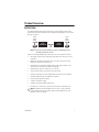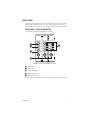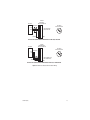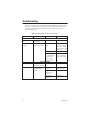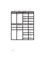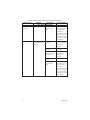
1
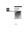
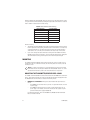
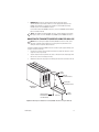
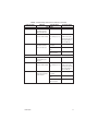
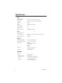
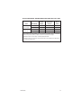
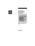
ADDENDUM
Addendum No.:
Date:
Manual Affected:
Manual Update:
C1648M ADDEN
April 29, 2005
FT85081/FR85081 Fiber Transmitter and Receiver
Installation Manual – C1648M
Attachment of Ferrite to Data Cable of FT85081 Transmitter
A snap-on ferrite is supplied with the FT85081MSTR,
FT85081SSTR, and FT85081SFCR transmitters. The ferrite
must be attached to the data cable of the transmitters to
comply with FCC and CE emissions requirements.
After data connections are made to the data connector on
the transmitter, attach the ferrite to the data cable. When
attaching the ferrite to the cable, position the ferrite as
close as possible to the transmitter.
NOTE: The ferrite should fit securely around the cable.
If the ferrite is loose and slides along the cable, loop the
cable through the ferrite before closing the ferrite.
If, however, the thickness of the cable prevents the ferrite
from closing, use a tie wrap to hold the ferrite in place
rather than looping the cable.
®
Pelco World Headquarters • 3500 Pelco Way, Clovis, California 93612-5699 USA
USA & Canada: Tel: 800/289-9100 • Fax: 800/289-9150
International: Tel: 1-559/292-1981 • Fax: 1-559/348-1120
www.pelco.com
I N S T A L L A T I O N
®
FT85081/FR85081
Fiber Transmitter
and Receiver
Eight-Channel Digitally Encoded Video
with Bidirectional Data
C1648M (4/05)
Contents
Important Safety Instructions . . . . . . . . . . . . . . . . . . . . . . . . . . . . . . . . . . . . . . . . . . . . . . . . . . . 4
Regulatory Notices . . . . . . . . . . . . . . . . . . . . . . . . . . . . . . . . . . . . . . . . . . . . . . . . . . . . . . . . . . . 6
Product Overview. . . . . . . . . . . . . . . . . . . . . . . . . . . . . . . . . . . . . . . . . . . . . . . . . . . . . . . . . . . . . 7
Description . . . . . . . . . . . . . . . . . . . . . . . . . . . . . . . . . . . . . . . . . . . . . . . . . . . . . . . . . . . . . 7
Models . . . . . . . . . . . . . . . . . . . . . . . . . . . . . . . . . . . . . . . . . . . . . . . . . . . . . . . . . . . . . . . . 8
Optional Accessories . . . . . . . . . . . . . . . . . . . . . . . . . . . . . . . . . . . . . . . . . . . . . . . . 8
Front Panel . . . . . . . . . . . . . . . . . . . . . . . . . . . . . . . . . . . . . . . . . . . . . . . . . . . . . . . . . . . . . 9
Front Panel - FT85081 Transmitter . . . . . . . . . . . . . . . . . . . . . . . . . . . . . . . . . . . . . . 9
Front Panel - FR85081 Receiver . . . . . . . . . . . . . . . . . . . . . . . . . . . . . . . . . . . . . . . 10
Rear Panel . . . . . . . . . . . . . . . . . . . . . . . . . . . . . . . . . . . . . . . . . . . . . . . . . . . . . . . . . . . . 11
Rear Panel - FT85081 Transmitter . . . . . . . . . . . . . . . . . . . . . . . . . . . . . . . . . . . . . 11
Rear Panel - FR85081 Receiver . . . . . . . . . . . . . . . . . . . . . . . . . . . . . . . . . . . . . . . 12
Installation . . . . . . . . . . . . . . . . . . . . . . . . . . . . . . . . . . . . . . . . . . . . . . . . . . . . . . . . . . . . . . . . . 13
Package Contents. . . . . . . . . . . . . . . . . . . . . . . . . . . . . . . . . . . . . . . . . . . . . . . . . . . . . . . 13
Data Communication Setup . . . . . . . . . . . . . . . . . . . . . . . . . . . . . . . . . . . . . . . . . . . . . . . 13
Mounting . . . . . . . . . . . . . . . . . . . . . . . . . . . . . . . . . . . . . . . . . . . . . . . . . . . . . . . . . . . . . 14
Mounting the Transmitter/Receiver into a Rack . . . . . . . . . . . . . . . . . . . . . . . . . . 14
Mounting the Transmitter/Receiver Using the Wall Clip. . . . . . . . . . . . . . . . . . . . 15
Connections. . . . . . . . . . . . . . . . . . . . . . . . . . . . . . . . . . . . . . . . . . . . . . . . . . . . . . . . . . . 16
Troubleshooting . . . . . . . . . . . . . . . . . . . . . . . . . . . . . . . . . . . . . . . . . . . . . . . . . . . . . . . . . . . . . 24
Specifications . . . . . . . . . . . . . . . . . . . . . . . . . . . . . . . . . . . . . . . . . . . . . . . . . . . . . . . . . . . . . . 28
List of Illustrations
1
2
3
4
5
6
7
8
9
10
11
12
13
14
2
Eight-Channel Video FT85081 Transmitter and FR85081 Receiver
with Bidirectional Data Channel . . . . . . . . . . . . . . . . . . . . . . . . . . . . . . . . . . . . . . . . . . . . 7
Front Panel of FT85081 Transmitter . . . . . . . . . . . . . . . . . . . . . . . . . . . . . . . . . . . . . . . . . . 9
Front Panel of FR85081 Receiver . . . . . . . . . . . . . . . . . . . . . . . . . . . . . . . . . . . . . . . . . . . 10
Rear Panel of FT85081 Transmitter . . . . . . . . . . . . . . . . . . . . . . . . . . . . . . . . . . . . . . . . . 11
Rear Panel of FR85081 Receiver . . . . . . . . . . . . . . . . . . . . . . . . . . . . . . . . . . . . . . . . . . . 12
Data Selection Switch . . . . . . . . . . . . . . . . . . . . . . . . . . . . . . . . . . . . . . . . . . . . . . . . . . . 13
Mounting the FT85081 Transmitter/FR85081 Receiver Using the Wall Clip. . . . . . . . . . 15
FT85081 Transmitter/FR85081 Receiver Connections . . . . . . . . . . . . . . . . . . . . . . . . . . . 16
RS-232 Data Communication Wiring . . . . . . . . . . . . . . . . . . . . . . . . . . . . . . . . . . . . . . . . 18
RS-422 Data Communication Wiring . . . . . . . . . . . . . . . . . . . . . . . . . . . . . . . . . . . . . . . . 19
RS-485 2-Wire (Half Duplex) Data Communication Wiring . . . . . . . . . . . . . . . . . . . . . . . 20
RS-485 4-Wire (Full Duplex) Data Communication Wiring . . . . . . . . . . . . . . . . . . . . . . . 21
Manchester Data Communication Wiring . . . . . . . . . . . . . . . . . . . . . . . . . . . . . . . . . . . . 22
Bi-Phase Data Communication Wiring . . . . . . . . . . . . . . . . . . . . . . . . . . . . . . . . . . . . . . 23
C1648M (4/05)
List of Tables
A
B
C
Data Selection Switch Settings . . . . . . . . . . . . . . . . . . . . . . . . . . . . . . . . . . . . . . . . . . . . 14
Data Connector Pin Assignments . . . . . . . . . . . . . . . . . . . . . . . . . . . . . . . . . . . . . . . . . . 17
Troubleshooting with Front-Panel Indicators . . . . . . . . . . . . . . . . . . . . . . . . . . . . . . . . . . 24
C1648M (4/05)
3
Important Safety Instructions
1. Read these instructions.
2. Keep these instructions.
3. Heed all warnings.
4. Follow all instructions.
5. Do not use this apparatus near water.
6. Clean only with dry cloth.
7. Do not block any ventilation openings. Install in accordance with the manufacturer’s
instructions.
8. Do not install near any heat sources such as radiators, heat registers, stoves, or other
apparatus (including amplifiers) that produce heat.
9. Do not defeat the safety purpose of the polarized or grounding-type plug. A polarized
plug has two blades with one wider than the other. A grounding plug has two blades
and a third grounding prong. The wide blade or the third prong are provided for your
safety. If the provided plug does not fit into your outlet consult an electrician for
replacement of the obsolete outlet.
10. Protect the power cord from being walked on or pinched particularly at plugs,
convenience receptacles, and the points where they exit from the apparatus.
11. Only use attachments/accessories specified by the manufacturer.
12. Use only with the cart, stand, tripod, bracket, or table specified by the manufacturer, or
sold with the apparatus. When a cart is used, use caution when moving the cart/
apparatus combination to avoid injury from tip-over.
13. Unplug this apparatus during lightning storms or when unused for long periods of time.
14. Refer all servicing to qualified service personnel. Servicing is required when the
apparatus has been damaged in any way, such as power-supply cord or plug is
damaged, liquid has been spilled or objects have fallen into the apparatus, the
apparatus has been exposed to rain or moisture, does not operate normally, or has been
dropped.
15. Apparatus shall not be exposed to dripping or splashing and that no objects filled with
liquids, such as vases shall be placed on the apparatus.
16. WARNING: To reduce the risk of fire or electric shock, do not expose this apparatus to
rain or moisture.
17. Installation should be done only by qualified personnel and conform to all local codes.
18. Unless the unit is specifically marked as a NEMA Type 3, 3R, 3S, 4, 4X, 6, or 6P
enclosure, it is designed for indoor use only and it must not be installed where exposed
to rain and moisture.
19. Use only installation methods and materials capable of supporting four times the
maximum specified load.
4
C1648M (4/05)
CAUTION: These servicing instructions are for use by qualified service personnel only.
To reduce the risk of electric shock do not perform any servicing other that contained in
the operating instructions unless you are qualified to do so.
The product and/or manual may bear the following marks:
This symbol indicates that dangerous voltage
constituting a risk of electric shock is present
within this unit.
This symbol indicates that there are important
operating and maintenance instructions in the
literature accompanying this unit.
C1648M (4/05)
CAUTION:
RISK OF ELECTRIC SHOCK.
DO NOT OPEN.
5
Regulatory Notices
This device complies with Part 15 of the FCC Rules. Operation is subject to the following two
conditions: (1) this device may not cause harmful interference, and (2) this device must accept
any interference received, including interference that may cause undesired operation.
RADIO AND TELEVISION INTERFERENCE
This equipment has been tested and found to comply with the limits of a Class A digital device,
pursuant to Part 15 of the FCC Rules. These limits are designed to provide reasonable protection
against harmful interference when the equipment is operated in a commercial environment.
This equipment generates, uses, and can radiate radio frequency energy and, if not installed
and used in accordance with the instruction manual, may cause harmful interference to radio
communications. Operation of this equipment in a residential area is likely to cause harmful
interference in which case the user will be required to correct the interference at his own
expense.
Changes and Modifications not expressly approved by the manufacturer or registrant of this
equipment can void your authority to operate this equipment under Federal Communications
Commission’s rules.
This Class A digital apparatus complies with Canadian ICES-003.
Cet appareil numérique de la classe A est conforme à la norme NMB-003 du Canada.
6
C1648M (4/05)
Product Overview
DESCRIPTION
The FT85081/FR85081 fiber transmitter and receiver provide the ability to transmit eight
unidirectional composite video channels and one bidirectional data channel over one optical
fiber (refer to Figure 1).
EIGHT
VIDEO
OUTPUTS
EIGHT
VIDEO
INPUTS
FT85081
TRANSMITTER
ONE
FIBER
FR85081
RECEIVER
DATA
DATA
Figure 1. Eight-Channel Video FT85081 Transmitter and FR85081 Receiver
with Bidirectional Data Channel
Features of the FT85081/FR85081 fiber optic transmission system include the following:
•
8-bit digitally encoded video for high-quality multi-channel video transmission over a
single fiber
•
Bidirectional data channel that supports RS-232, RS-422, RS-485 (2-wire/4-wire),
Manchester, and Bi-Phase communication
•
Wavelength division multiplexing (WDM), allowing video and data channels to be
transmitted in the same fiber using different wavelengths
•
Multimode fiber support for distances up to 1 km (0.6 mi)
•
Single-mode fiber support for distances up to 30 km (18.6 mi)
•
Exceeds all requirements for the RS-250C Medium-Haul Transmission specification
•
Compatible with NTSC, PAL, and SECAM video standards
•
No performance adjustments required
•
12 VDC or 24 VAC power supply
•
Standalone and rack-mountable modular design
•
LED indicators for monitoring of signal status, data activity, and operating power
NOTE: The FT85081 transmitter/FR85081 receiver is a Class 1 laser product that
complies with FDA radiation performance standard 21CFR Subchapter J and with
IEC 60825-1 Edition 1.2, 2001-08.
C1648M (4/05)
7
MODELS
The FT85081/FR85081 fiber transmitter and receiver consist of the following series of models:
Multimode Models:
FT85081MSTR
Eight-channel fiber optic video transmitter/single-channel data transceiver;
multimode, ST connector
FR85081MSTR
Eight-channel fiber optic video receiver/single-channel data transceiver;
multimode, ST connector
Single-Mode Models:
FT85081SSTR
Eight-channel fiber optic video transmitter/single-channel data transceiver;
single-mode, ST connector
FR85081SSTR
Eight-channel fiber optic video receiver/single-channel data transceiver;
single-mode, ST connector
FT85081SFCR
Eight-channel fiber optic video transmitter/single-channel data transceiver;
single-mode, FC connector
FR85081SFCR
Eight-channel fiber optic video receiver/single-channel data transceiver;
single-mode, FC connector
OPTIONAL ACCESSORIES
The following optional accessories are available:
RK5000-3U
19-inch rack mount chassis for 14 slots (no power), 3 RUs
RK5000PS-3U
19-inch rack mount chassis for 12 slots with power, 3 RUs
EPS5000-120
External/redundant power supply, 1 RU, 120 W x 2
RK5001B-3U
Blank filler panel, single width
RK5002B-3U
Blank filler panel, double width
RK5003-1UEXP
Adapter kit that allows a 3 RU triple-width fiber optic module to be used in
RK5000PS-5U rack mount chassis
8
C1648M (4/05)
FRONT PANEL
The front panel of the FT85081 transmitter and the FR85081 receiver provides LED indicators
that allow you to monitor data activity, signal status, and operating power. The following
sections provide a view of the front panel of the FT85081 transmitter and the FR85081 receiver.
FRONT PANEL - FT85081 TRANSMITTER
Figure 2 illustrates the front panel of the FT85081 transmitter.
8
4
Tx
7
3
Rx
6
2
5
1
Figure 2. Front Panel of FT85081 Transmitter
DATA TX LED
DATA RX LED
CARRIER DETECT LED
POWER LED (Pelco badge)
VIDEO PRESENT LEDs (1-8)
For detailed information about the front-panel indicators, refer to the Troubleshooting section.
C1648M (4/05)
9
FRONT PANEL - FR85081 RECEIVER
Figure 3 illustrates the front panel of the FR85081 receiver.
8
4
Tx
7
3
Rx
6
2
5
1
Figure 3. Front Panel of FR85081 Receiver
DATA TX LED
DATA RX LED
POWER LED (Pelco badge)
VIDEO PRESENT LEDs (1-8)
CARRIER DETECT LED
For detailed information about the front-panel indicators, refer to the Troubleshooting section.
10
C1648M (4/05)
REAR PANEL
Connections to the FT85081 transmitter and the FR85081 receiver are made to the rear panel
of the module. The following sections provide a view of the rear panel of the FT85081
transmitter and the FR85081 receiver.
REAR PANEL - FT85081 TRANSMITTER
Figure 4 illustrates the rear panel of the FT85081 transmitter.
1
2
3
4
5
6
7
8
GND
8
7
6
3
12 4
0
9
5
8 7 6
5
Figure 4. Rear Panel of FT85081 Transmitter
RACK POWER/ALARM CONNECTOR, 4-pin connector for power/alarm connection of
rack-mounted module
STANDALONE POWER CONNECTOR, 2-pin connector for power connection of standalone
module; removable mating connector with screw terminals (not shown)
VIDEO IN CONNECTORS (1-8), 75-ohm BNC analog video input
FIBER OPTIC CONNECTOR, ST or FC (dependent on FT85081 model)
DATA CONNECTOR, 9-pin connector; removable mating connector with screw terminals
(not shown)
DATA SELECTION SWITCH, 10-position rotary switch (positions 0-9)
For additional information about rear-panel connections and about the Data Selection switch,
refer to the Installation section.
C1648M (4/05)
11
REAR PANEL - FR85081 RECEIVER
Figure 5 illustrates the rear panel of the FR85081 receiver.
1
2
3
4
5
6
7
8
GND
8
7
6
3
12 4
0
9
5
8 7 6
5
Figure 5. Rear Panel of FR85081 Receiver
RACK POWER/ALARM CONNECTOR, 4-pin connector for power/alarm connection of
rack-mounted module
STANDALONE POWER CONNECTOR, 2-pin connector for power connection of standalone
module; removable mating connector with screw terminals (not shown)
VIDEO OUT CONNECTORS (1-8), 75-ohm BNC analog video output
FIBER OPTIC CONNECTOR, ST or FC (dependent on FR85081 model)
DATA CONNECTOR, 9-pin connector; removable mating connector with screw terminals
DATA SELECTION SWITCH, 10-position rotary switch (positions 0-9)
For additional information about rear-panel connections and about the Data Selection switch,
refer to the Installation section.
12
C1648M (4/05)
Installation
PACKAGE CONTENTS
The following items are supplied:
•
With the FT85081 transmitter:
1
Regulated switching power supply with four plug adapters (North American,
Australian, U.K., and European configurations); 100-240 VAC input, 12 VDC output
1
Wall clip with two 4-40 x .250-inch Phillips pan head screws with lock washers
(for attachment of single module to wall)
1
FT85081/FR85081 Fiber Transmitter and Receiver Installation manual (this manual)
•
With the FR85081 receiver:
1
Regulated switching power supply with four plug adapters (North American,
Australian, U.K., and European configurations); 100-240 VAC input, 12 VDC output
1
Wall clip with two 4-40 x .250-inch Phillips pan head screws with lock washers
(for attachment of single module to wall)
1
FT85081/FR85081 Fiber Transmitter and Receiver Installation manual (this manual)
DATA COMMUNICATION SETUP
NOTE: As a matter of convenience, it is recommended that you set the desired data
communication before mounting the FT85081 transmitter/FR85081 receiver into a rack
or onto a wall.
The Data Selection switch, which is located on the rear panel of the FT85081 transmitter/
FR85081 receiver, is a 10-position rotary switch that allows you to set the data communication
required for the transfer of data (refer to Figure 6).
7
3
12 4
0
6
9
5
5
8 7 6
3
12 4
0
1
2
3
4
5
6
7
8
GND
8
9
5
8 7 6
DATA
SELECTION
SWITCH
Figure 6. Data Selection Switch
C1648M (4/05)
13
With the FT85081 transmitter/FR85081 receiver powered off, turn the Data Selection switch
using a screwdriver until the number representing the required data communication is selected.
Refer to Table A for Data Selection switch settings.
Table A. Data Selection Switch Settings
Data Selection
Switch Setting
RS-232
0 (default setting)
RS-422
1
RS-485 2-Wire
2
RS-485 4-Wire
3
Manchester/Bi-Phase
4
Not used
5-9
Note the following:
•
The FT85081 transmitter/FR85081 receiver allows data translation between RS-232 and
RS-422 signal levels. Consequently, the Data Selection switch can be set to 0 (RS-232)
on the transmitter and to 1 (RS-422) on the receiver. Conversely, the Data Selection
switch can be set to 1 (RS-422) on the transmitter and to 0 (RS-232) on the receiver.
•
If you wish to change the data communication setting after the FT85081 transmitter/
FR85081 receiver has been powered on, power off the transmitter/receiver, change the
data communication setting, and then power on the transmitter/receiver again.
MOUNTING
The FT85081 transmitter/FR85081 receiver can be mounted into a rack or can be used as a
standalone module. As a standalone module, the unit can be placed on a desktop or can be
mounted to a wall.
NOTE: As a matter of convenience, it is recommended that you set the desired data
communication before mounting the FT85081 transmitter/FR85081 receiver. To set the
desired data communication, refer to the Data Communication Setup section.
MOUNTING THE TRANSMITTER/RECEIVER INTO A RACK
The FT85081 transmitter/FR85081 receiver can be installed into the RK5000 Series rack mount
chassis, which can be mounted into an industry-standard 19-inch (48.26 cm) equipment rack.
The RK5000 Series rack mount chassis includes the following models:
•
14
RK5000PS-3U and RK5000-3U: Designed to accommodate fiber optic modules as
follows:
–
The RK5000PS-3U rack mount chassis provides 12 single-width module slots and
a power supply.
–
The RK5000-3U rack mount chassis provides 14 single-width module slots (a
power supply is not included). Power to the modules can be supplied using the
optional external power supply (EPS5000-120).
For additional information, refer to the RK5000PS-3U/RK5000-3U Fiber Rack Mount
Chassis Installation manual.
C1648M (4/05)
•
RK5000PS-5U: Designed to accommodate Endura™ modules but can also
accommodate fiber optic modules with the use of the appropriate adapter kit. The
RK5003-1UEXP adapter kit is required for installation of the FT85081 transmitter/
FR85081 receiver into the RK5000PS-5U chassis.
For information about the RK5000PS-5U chassis, refer to the RK5000PS-5U Rack Mount
Chassis Installation manual.
NOTE: The FT85081 transmitter/FR85081 receiver is a triple-width fiber optic module
that occupies three slots in the RK5000PS-3U, RK5000-3U, and RK5000PS-5U chassis.
MOUNTING THE TRANSMITTER/RECEIVER USING THE WALL CLIP
NOTE: Before mounting the FT85081 transmitter/FR85081 receiver to a wall, ensure
that there is adequate space at both ends for viewing the front-panel LEDs and for
making the various rear-panel cable connections.
To attach the FT85081 transmitter/FR85081 receiver to a wall using the supplied wall clip, refer
to Figure 7 and do the following:
1.
Using the two vertical or horizontal wall-mounting holes, attach the wall clip to a wall
using two screws (not provided).
2.
Slide the module into the clip until the two holes on the bottom of the module align with
the two holes on the lower flange of the clip.
3.
Attach the module to the clip using the two Phillips pan head screws provided for the clip.
UPPER
FLANGE
VERTICAL
MOUNTING HOLE (2)
HORIZONTAL
MOUNTING HOLE (2)
TRANSMITTER/
RECEIVER
SCREW, PHILLIPS
PAN HEAD WITH
LOCK WASHER (2)
WALL CLIP
LOWER
FLANGE
Figure 7. Mounting the FT85081 Transmitter/FR85081 Receiver Using the Wall Clip
C1648M (4/05)
15
CONNECTIONS
Connections to the FT85081 transmitter and the FR85081 receiver are made on the rear panel
of the modules and consist of the following:
•
Power connection
NOTE: A 12 VDC or 24 VAC power supply can be used to power the transmitter/receiver
when used as a standalone module. A 12 VDC power supply is provided. If a 24 VAC
power supply is used, the power supply must be a Listed Direct Plug-In Power Unit
marked as Class 2 and rated as 24 VAC, 200 mA (minimum output).
•
Video input connections (transmitter only)
•
Video output connections (receiver only)
•
Fiber connection
•
Data connection
Figure 8 provides an illustration of FT85081 transmitter/FR85081 receiver connections.
POWER/ALARM
CONNECTION FOR
RACK-MOUNTED MODULE*
FIBER OPTIC CABLE
POWER CONNECTION
FOR STANDALONE MODULE†
COAXIAL
CABLE
1
2
3
4
5
6
7
8
GND
8
7
3
12 4
0
6
9
COAXIAL
CABLE
5
5
8 7 6
DATA COMMUNICATION
CABLE (REFER TO TABLE B
FOR DATA CONNECTOR
PIN ASSIGNMENTS AND
TO FIGURES 9-14 FOR
WIRING DIAGRAMS)
*REFER TO THE RK5000PS-3U/RK5000-3U FIBER RACK MOUNT CHASSIS INSTALLATION
MANUAL FOR INFORMATION.
† THE STRIPED WIRE OF THE SUPPLIED 12 VDC POWER SUPPLY CONNECTS TO THE
PIN 1 SCREW TERMINAL (DC+) OF THE STANDALONE POWER CONNECTOR. THE
OTHER WIRE CONNECTS TO THE PIN 2 SCREW TERMINAL (DC-).
Figure 8. FT85081 Transmitter/FR85081 Receiver Connections
16
C1648M (4/05)
Table B. Data Connector Pin Assignments
Pin
Number RS-232
RS-422
RS-485
2-Wire
RS-485
4-Wire
Manchester
Bi-Phase
1
—
Out+
In+/Out+
Out+
—
2
—
Out-
In-/Out-
Out-
—
—
—
3
—
In+
—
In+
In+ (W)
In+
4
—
In-
—
In-
In- (B)
In-
5
In
—
—
—
—
—
6
Out
—
—
—
—
—
7
—
—
—
—
Out+ (W)
Out+
8
—
—
—
—
Out- (B)
Out-
9
Ground
—*
—*
—*
Shield
Shield
*Ground may be required based on conditions of installation. Refer to the current version of
EIA/TIA-422 and EIA/TIA-485 standards for additional information.
NOTES:
•
In, In+, and In- denote data input to the transmitter/receiver.
•
Out, Out+, and Out- denote data output from the transmitter/receiver.
•
W denotes white wire, and B denotes black wire.
C1648M (4/05)
17
FR85081
RECEIVER –
DATA CONNECTOR
RX
TX
GND
RS-232
1
2
3
4
5 (RX) DATA IN
6 (TX) DATA OUT
7
8
GND
RS-232
DATA SELECTION
3
12 4
0
DEVICE A
9
5
8 7 6
RS-232 DATA CONNECTIONS BETWEEN DEVICE A AND FR85081 RECEIVER
FT85081
TRANSMITTER –
DATA CONNECTOR
RX
TX
GND
RS-232
1
2
3
4
5 (RX) DATA IN
6 (TX) DATA OUT
7
8
GND
RS-232
DATA SELECTION
3
12 4
0
DEVICE B
9
5
8 7
6
RS-232 DATA CONNECTIONS BETWEEN DEVICE B AND FT85081 TRANSMITTER
Figure 9. RS-232 Data Communication Wiring
18
C1648M (4/05)
RS-422
5
6
7
8
GND
RS-422
DATA SELECTION
3
12 4
0
DEVICE A
RX+
RXTX+
TX-
FR85081
RECEIVER –
DATA CONNECTOR
1 (TX+) DATA OUT+
2 (TX-) DATA OUT3 (RX+) DATA IN+
4 (RX-) DATA IN-
9
5
8 7
6
RS-422 DATA CONNECTIONS BETWEEN DEVICE A AND FR85081 RECEIVER
RS-422
5
6
7
8
GND
RS-422
DATA SELECTION
3
12 4
0
DEVICE B
RX+
RXTX+
TX-
FT85081
TRANSMITTER –
DATA CONNECTOR
1 (TX+) DATA OUT+
2 (TX-) DATA OUT3 (RX+) DATA IN+
4 (RX-) DATA IN-
9
5
8 7 6
RS-422 DATA CONNECTIONS BETWEEN DEVICE B AND FT85081 TRANSMITTER
Figure 10. RS-422 Data Communication Wiring
C1648M (4/05)
19
FR85081
RECEIVER –
DATA CONNECTOR
1 (TX+/RX+) DATA OUT+/DATA IN+
2 (TX-/RX-) DATA OUT-/DATA IN-
3
4
5
6
7
8
GND
RS-485 2-WIRE
DATA SELECTION
3
12 4
0
DEVICE A
RX+/TX+
RX-/TX-
RS-485
2-WIRE
9
5
8 7 6
RS-485 2-WIRE DATA CONNECTIONS BETWEEN DEVICE A AND FR85081 RECEIVER
RS-485
2-WIRE
1 (TX+/RX+) DATA OUT+/DATA IN+
2 (TX-/RX-) DATA OUT-/DATA IN3
4
5
6
7
8
GND
RS-485 2-WIRE
DATA SELECTION
3
12 4
0
DEVICE B
RX+/TX+
RX-/TX-
FT85081
TRANSMITTER –
DATA CONNECTOR
9
5
8 7
6
RS-485 2-WIRE DATA CONNECTIONS BETWEEN DEVICE B AND FT85081 TRANSMITTER
Figure 11. RS-485 2-Wire (Half Duplex) Data Communication Wiring
20
C1648M (4/05)
FR85081
RECEIVER –
DATA CONNECTOR
1 (TX+) DATA OUT+
2 (TX-) DATA OUT3 (RX+) DATA IN+
4 (RX-) DATA IN5
6
7
8
GND
RS-485 4-WIRE
DATA SELECTION
3
12 4
0
DEVICE A
RX+
RXTX+
TX-
RS-485
4-WIRE
9
5
8 7 6
RS-485 4-WIRE DATA CONNECTIONS BETWEEN DEVICE A AND FR85081 RECEIVER
RS-485
4-WIRE
1 (TX+) DATA OUT+
2 (TX-) DATA OUT3 (RX+) DATA IN+
4 (RX-) DATA IN5
6
7
8
GND
RS-485 4-WIRE
DATA SELECTION
3
12 4
0
DEVICE B
RX+
RXTX+
TX-
FT85081
TRANSMITTER –
DATA CONNECTOR
9
5
8 7
6
RS-485 4-WIRE DATA CONNECTIONS BETWEEN DEVICE B AND FT85081 TRANSMITTER
Figure 12. RS-485 4-Wire (Full Duplex) Data Communication Wiring
C1648M (4/05)
21
FR85081
RECEIVER –
DATA CONNECTOR
MANCHESTER
W*
B*
SHIELD
1
2
3 (RX+) DATA IN+
4 (RX-) DATA IN5
6
7
8
GND
MANCHESTER
DATA SELECTION
3
12 4
0
DEVICE A
9
5
8 7 6
MANCHESTER DATA CONNECTIONS BETWEEN DEVICE A AND FR85081 RECEIVER
FT85081
TRANSMITTER –
DATA CONNECTOR
MANCHESTER
W*
B*
SHIELD
1
2
3
4
5
6
7 (TX+) DATA OUT+
8 (TX-) DATA OUTGND
MANCHESTER
DATA SELECTION
3
12 4
0
DEVICE B
9
5
8 7 6
MANCHESTER DATA CONNECTIONS BETWEEN DEVICE B AND FT85081 TRANSMITTER
*W DENOTES WHITE WIRE, AND B DENOTES BLACK WIRE.
Figure 13. Manchester Data Communication Wiring
22
C1648M (4/05)
FR85081
RECEIVER –
DATA CONNECTOR
BI-PHASE
OUT+
OUT-
SHIELD
1
2
3 (RX+) DATA IN+
4 (RX-) DATA IN5
6
7
8
GND
BI-PHASE
DATA SELECTION
3
12 4
0
DEVICE A
9
5
8 7 6
BI-PHASE DATA CONNECTIONS BETWEEN DEVICE A AND FR85081 RECEIVER
FT85081
TRANSMITTER –
DATA CONNECTOR
IN+
IN-
BI-PHASE
SHIELD
1
2
3
4
5
6
7 (TX+) DATA OUT+
8 (TX-) DATA OUTGND
BI-PHASE
DATA SELECTION
3
12 4
0
DEVICE B
9
5
8 7
6
BI-PHASE DATA CONNECTIONS BETWEEN DEVICE B AND FT85081 TRANSMITTER
Figure 14. Bi-Phase Data Communication Wiring
C1648M (4/05)
23
Troubleshooting
LED indicators on the front panel of the FT85081 transmitter/FR85081 receiver (refer to Figure 2
and Figure 3, respectively) allow you to monitor signal status, data activity, and operating
power. Table C provides information about the front-panel indicators and associated
troubleshooting guidelines.
Table C. Troubleshooting with Front-Panel Indicators
Indicator Color
Meaning
Possible Cause
Power LED (Pelco badge)
Blue Pelco logo lights. Power is being applied –
to the module.
Blue Pelco logo does Power is not being
Power connection is
not light.
applied to the module. faulty.
Green
Red on transmitter
24
Corrective Action
No action required.
Check power
connection. If module is
rack mounted, reseat
module or power supply
as necessary.
Power supply has failed. Replace power supply.
Loss of power occurs
Check circuit breaker(s),
due to tripped circuit
fuse(s), or electrical
breaker(s), blown
service as necessary.
fuse(s), or faulty
electrical service.
Video Present LED
Incoming video signal is —
No action required.
present on the channel.
Incoming video signal is Video source is not
Check power connection
not present on the
powered on.
to the video source.
channel.
Video source is not
Check BNC connections.
connected to the
transmitter.
Coaxial cable is
Replace cable.
defective.
(Continued on next page)
C1648M (4/05)
Table C. Troubleshooting with Front-Panel Indicators (Continued)
Indicator Color
Meaning
Possible Cause
Video Present LED (Continued)
Red on receiver
Incoming video signal is Optical signal is not
not present on the
being received from the
channel.
transmitter. Carrier
Detect LED is also red.
Video source is not
powered on.
Video source is not
connected to the
transmitter.
Coaxial cable connected
to the transmitter is
defective.
Carrier Detect LED
Green on transmitter The optical signal is
—
being received from the
receiver.
Green on receiver
The optical signal is
—
being received from the
transmitter.
Red on transmitter
The optical signal is not Receiver is not powered
being received from the on.
receiver.
Fiber optic cable is not
connected.
Fiber optic cable
connectors are dirty or
are damaged.
Fiber optic cable is
defective.
Corrective Action
Refer to the Carrier
Detect LED
troubleshooting section
below.
Check power connection
to the video source.
Check BNC connections.
Replace cable.
No action required.
No action required.
Check power
connections. Replace
power supply if
necessary.
Check fiber optic
connections.
Clean, polish, or replace
fiber optic cable
connectors as
necessary.
Replace cable.
(Continued on next page)
C1648M (4/05)
25
Table C. Troubleshooting with Front-Panel Indicators (Continued)
Indicator Color
Red on transmitter
(continued)
Red on receiver
Meaning
Possible Cause
Carrier Detect LED (Continued)
A problem exists with
the optical power
budget.
The optical signal is not Transmitter is not
being received from the powered on.
transmitter.
Fiber optic cable is not
connected.
Fiber optic cable
connectors are dirty or
are damaged.
Fiber optic cable is
defective.
A problem exists with
the optical power
budget.
26
Corrective Action
Verify that losses in
fiber optic cable do not
exceed the optical
power budget
specification of the fiber
optic link. If the losses
do exceed the optical
power budget, contact
Product Support.
Check power
connections. Replace
power supply if
necessary.
Check fiber optic
connections.
Clean, polish, or replace
fiber optic cable
connectors as
necessary.
Replace cable.
Verify that losses in
fiber optic cable do not
exceed the optical
power budget
specification of the fiber
optic link. If the losses
do exceed the optical
power budget, contact
Product Support.
(Continued on next page)
C1648M (4/05)
Table C. Troubleshooting with Front-Panel Indicators (Continued)
Indicator Color
Flashing amber
Red
Not lit
Flashing amber
Red
Not lit
C1648M (4/05)
Meaning
Possible Cause
Data Tx LED
Data is being
—
transmitted onto the
fiber by the data port.
Data Selection switch is Data Selection switch is
set to an invalid setting. set to setting 5, 6, 7, 8,
or 9.
Data is not being
transmitted onto the
fiber by the data port.
Data is not present on
the channel.
Data connection is
faulty.
Data communication
cable is defective.
Data Rx LED
Data is being received —
from the fiber by the
data port.
Data Selection switch is Data Selection switch is
set to an invalid setting. set to setting 5, 6, 7, 8,
or 9.
Data is not being
received from the fiber
by the data port.
Data is not present on
the channel.
Data connection is
faulty.
Data communication
cable is defective.
Corrective Action
No action required.
Set Data Selection
switch to the correct
setting for the desired
data communication
(refer to Table A).
No action required.
Check data connections.
Replace cable.
No action required.
Set Data Selection
switch to the correct
setting for the desired
data communication
(refer to Table A).
No action required.
Check data connections.
Replace cable.
27
Specifications
VIDEO
Number of Channels
Modulation Type
Video Input
Bandwidth
Gain
Crosstalk
Differential Gain
Differential Phase
Tilt
Signal-to-Noise Ratio
DATA
Number of Channels
Data Communication
Maximum Baud Rate
GENERAL
Operating Temperature
Input Power Requirements
LED Indicators
Dimensions
Unit Weight
MECHANICAL
Connectors
Video
Rack Power/Alarm
Standalone Power
Data
Fiber Optic
28
8
Pulse code modulation, 8-bit resolution
1.0 Vp-p, 75 ohms; NTSC, PAL, and SECAM
6.5 MHz
Unity
-50 dB typical at 3.58 MHz
<1%
<1.2°
<1%
>60 dB (CCIR weighted)
1
RS-232, RS-422, RS-485 (2-wire/4-wire), Manchester,
Bi-Phase
500 kbps
-40° to 167°F (-40° to 75°C)
12 VDC or 24 VAC, 600 mA
Power
Video Present (per channel)
Carrier Detect
Data Tx
Data Rx
8.75” D x 3.48” W x 4.81” H
22.23 x 8.84 x 12.22 cm
3.50 lb (1.59 kg)
BNC (per channel)
4-pin connector
2-pin connector, screw terminal
9-pin connector, screw terminal
ST for multimode fiber
ST or FC for single-mode fiber
C1648M (4/05)
OPTICAL POWER BUDGET, TRANSMISSION DISTANCE, AND LASER CLASS 1 LIMIT
Fiber
Wavelength
Optical
Power
Budget
Multimode
(62.5/125 µm)
1310 nm (video)
20 dB†
1 km (0.6 mi)††
†
††
Single-mode
(9/125 µm)
850 nm (data)
1310 nm (video)
1550 nm (data)
20 dB
20 dB
20 dB
Maximum
Transmission
Distance
Laser
Class 1
Limit*
<15.6 mW
1 km (0.6 mi)
<0.78 mW
30 km (18.6 mi)
§
<15.6 mW
30 km (18.6 mi)
§
<10.0 mW
*The FT85081 transmitter/FR85081 receiver is classified by the FDA as a Class 1 laser product.
†
When using 50/125 µm fiber, subtract 3 dB from the optical power budget.
††
Maximum transmission distance is limited by fiber bandwidth.
§
Maximum transmission distance is based on attenuation of 0.5 dB/km plus a 5 dB buffer for
connector and splice losses.
C1648M (4/05)
29
PRODUCT WARRANTY AND RETURN INFORMATION
WARRANTY
Pelco will repair or replace, without charge, any merchandise proved defective in material or workmanship for a period of one year after the date of
shipment.
Exceptions to this warranty are as noted below:
• Five years on FT/FR8000 Series fiber optic products.
• Three years on Genex® Series products (multiplexers, server, and keyboard).
• Three years on Camclosure® and fixed camera models, except the CC3701H-2, CC3701H-2X, CC3751H-2, CC3651H-2X, MC3651H-2, and
MC3651H-2X camera models, which have a five-year warranty.
• Two years on standard motorized or fixed focal length lenses.
• Two years on Legacy®, CM6700/CM6800/CM9700 Series matrix, and DF5/DF8 Series fixed dome products.
• Two years on Spectra®, Esprit®, ExSite™, and PS20 scanners, including when used in continuous motion applications.
• Two years on Esprit® and WW5700 Series window wiper (excluding wiper blades).
• Eighteen months on DX Series digital video recorders, NVR300 Series network video recorders, and Endura™ Series distributed network-based video
products.
• One year (except video heads) on video cassette recorders (VCRs). Video heads will be covered for a period of six months.
• Six months on all pan and tilts, scanners or preset lenses used in continuous motion applications (that is, preset scan, tour and auto scan modes).
Pelco will warrant all replacement parts and repairs for 90 days from the date of Pelco shipment. All goods requiring warranty repair shall be sent freight
prepaid to Pelco, Clovis, California. Repairs made necessary by reason of misuse, alteration, normal wear, or accident are not covered under this
warranty.
Pelco assumes no risk and shall be subject to no liability for damages or loss resulting from the specific use or application made of the Products. Pelco’s
liability for any claim, whether based on breach of contract, negligence, infringement of any rights of any party or product liability, relating to the Products
shall not exceed the price paid by the Dealer to Pelco for such Products. In no event will Pelco be liable for any special, incidental or consequential
damages (including loss of use, loss of profit and claims of third parties) however caused, whether by the negligence of Pelco or otherwise.
The above warranty provides the Dealer with specific legal rights. The Dealer may also have additional rights, which are subject to variation from state
to state.
If a warranty repair is required, the Dealer must contact Pelco at (800) 289-9100 or (559) 292-1981 to obtain a Repair Authorization number (RA), and
provide the following information:
1. Model and serial number
2. Date of shipment, P.O. number, Sales Order number, or Pelco invoice number
3. Details of the defect or problem
If there is a dispute regarding the warranty of a product which does not fall under the warranty conditions stated above, please include a written
explanation with the product when returned.
Method of return shipment shall be the same or equal to the method by which the item was received by Pelco.
RETURNS
In order to expedite parts returned to the factory for repair or credit, please call the factory at (800) 289-9100 or (559) 292-1981 to obtain an authorization
number (CA number if returned for credit, and RA number if returned for repair).
All merchandise returned for credit may be subject to a 20% restocking and refurbishing charge.
Goods returned for repair or credit should be clearly identified with the assigned CA or RA number and freight should be prepaid. Ship to the appropriate
address below.
If you are located within the continental U.S., Alaska, Hawaii or Puerto Rico, send goods to:
Service Department
Pelco
3500 Pelco Way
Clovis, CA 93612-5699
If you are located outside the continental U.S., Alaska, Hawaii or Puerto Rico and are instructed to return goods to the USA, you may do one of the
following:
If the goods are to be sent by a COURIER SERVICE, send the goods to:
Pelco
3500 Pelco Way
Clovis, CA 93612-5699 USA
If the goods are to be sent by a FREIGHT FORWARDER, send the goods to:
Pelco c/o Expeditors
473 Eccles Avenue
South San Francisco, CA 94080 USA
Phone: 650-737-1700
Fax: 650-737-0933
REVISION HISTORY
Manual #
C1648M
Date
4/05
Comments
Original version.
Pelco, the Pelco logo, Spectra, Genex, Legacy, Esprit, and Camclosure are registered trademarks of Pelco.
Endura is a trademark of Pelco.
©Copyright 2005, Pelco.
All rights reserved.
Worldwide Headquarters
3500 Pelco Way
Clovis, California 93612 USA
USA & Canada
Tel: 800/289-9100
Fax: 800/289-9150
International
Tel: 1-559/292-1981
Fax: 1-559/348-1120
www.pelco.com
ISO9001
United States | Canada | United Kingdom | The Netherlands | Singapore | Spain | Scandinavia | France | Middle East