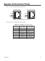
1
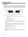
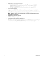
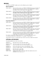
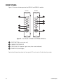
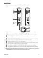
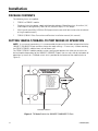
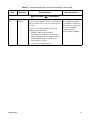
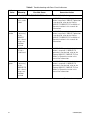
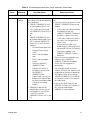
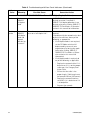
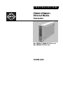
I N S T A L L A T I O N
®
FT82011/FR82011
Ethernet Media
Converter
One 10BASE-T/100BASE-TX Port and
One 100BASE-FX Fiber Port
C2653M (6/07)
Contents
Important Safety Instructions . . . . . . . . . . . . . . . . . . . . . . . . . . . . . . . . . . . . . . . . . . . . . . . . . . . 4
Regulatory Notices . . . . . . . . . . . . . . . . . . . . . . . . . . . . . . . . . . . . . . . . . . . . . . . . . . . . . . . . . . . 6
Product Overview . . . . . . . . . . . . . . . . . . . . . . . . . . . . . . . . . . . . . . . . . . . . . . . . . . . . . . . . . . . . 7
Description . . . . . . . . . . . . . . . . . . . . . . . . . . . . . . . . . . . . . . . . . . . . . . . . . . . . . . . . . . . . 7
Models. . . . . . . . . . . . . . . . . . . . . . . . . . . . . . . . . . . . . . . . . . . . . . . . . . . . . . . . . . . . . . . . 9
Optional Accessories . . . . . . . . . . . . . . . . . . . . . . . . . . . . . . . . . . . . . . . . . . . . . . . . 9
Front Panel. . . . . . . . . . . . . . . . . . . . . . . . . . . . . . . . . . . . . . . . . . . . . . . . . . . . . . . . . . . . 10
Rear Panel . . . . . . . . . . . . . . . . . . . . . . . . . . . . . . . . . . . . . . . . . . . . . . . . . . . . . . . . . . . . 11
Installation . . . . . . . . . . . . . . . . . . . . . . . . . . . . . . . . . . . . . . . . . . . . . . . . . . . . . . . . . . . . . . . .
Package Contents . . . . . . . . . . . . . . . . . . . . . . . . . . . . . . . . . . . . . . . . . . . . . . . . . . . . . .
Setting 10BASE-T/100BASE-TX Port Modes of Operation. . . . . . . . . . . . . . . . . . . . . . .
Mounting . . . . . . . . . . . . . . . . . . . . . . . . . . . . . . . . . . . . . . . . . . . . . . . . . . . . . . . . . . . . .
Mounting the FT82011/FR82011 Module into a Rack . . . . . . . . . . . . . . . . . . . . .
Mounting the FT82011/FR82011 Module to a Wall . . . . . . . . . . . . . . . . . . . . . . .
Connections. . . . . . . . . . . . . . . . . . . . . . . . . . . . . . . . . . . . . . . . . . . . . . . . . . . . . . . . . . .
12
12
12
14
14
14
16
Troubleshooting . . . . . . . . . . . . . . . . . . . . . . . . . . . . . . . . . . . . . . . . . . . . . . . . . . . . . . . . . . . . 18
Specifications . . . . . . . . . . . . . . . . . . . . . . . . . . . . . . . . . . . . . . . . . . . . . . . . . . . . . . . . . . . . . . 27
Appendix. RJ-45 Connector Pinouts . . . . . . . . . . . . . . . . . . . . . . . . . . . . . . . . . . . . . . . . . . . . . 29
List of Illustrations
1
2
3
4
5
6
7
FT82011 and FR82011 Point-to-Point Application. . . . . . . . . . . . . . . . . . . . . . . . . . . . . . . 7
Front Panel of FT82011 and FR82011 Modules. . . . . . . . . . . . . . . . . . . . . . . . . . . . . . . . 10
Rear Panel of FT82011 and FR82011 Modules (SC Fiber Connector Shown) . . . . . . . . . 11
TX Mode Switch for 10BASE-T/100BASE-TX Port . . . . . . . . . . . . . . . . . . . . . . . . . . . . . 12
Mounting the FT82011/FR82011 Module Using the Wall Clip . . . . . . . . . . . . . . . . . . . . 15
FT82011/FR82011 Module Connections . . . . . . . . . . . . . . . . . . . . . . . . . . . . . . . . . . . . . 16
RJ-45 MDI/MDI-X Connector Pinouts. . . . . . . . . . . . . . . . . . . . . . . . . . . . . . . . . . . . . . . 29
List of Tables
A
B
C
D
C2653M (6/07)
TX Mode Switch Settings . . . . . . . . . . . . . . . . . . . . . . . . . . . . . . . . . . . . . . . . . . . . . . . .
Troubleshooting with Front-Panel Indicators . . . . . . . . . . . . . . . . . . . . . . . . . . . . . . . . .
Troubleshooting with Rear-Panel Indicators. . . . . . . . . . . . . . . . . . . . . . . . . . . . . . . . . .
RJ-45 MDI/MDI-X Connector Pinouts. . . . . . . . . . . . . . . . . . . . . . . . . . . . . . . . . . . . . . .
13
18
22
29
3
Important Safety Instructions
1. Read these instructions.
2. Keep these instructions.
3. Heed all warnings.
4. Follow all instructions.
5. Do not use this apparatus near water.
6. Clean only with dry cloth.
7. Do not block any ventilation openings. Install in accordance with the manufacturer’s
instructions.
8. Do not install near any heat sources such as radiators, heat registers, stoves, or other
apparatus (including amplifiers) that produce heat.
9. Do not defeat the safety purpose of the polarized or grounding-type plug. A polarized plug has
two blades with one wider than the other. A grounding plug has two blades and a third
grounding prong. The wide blade or the third prong are provided for your safety. If the provided
plug does not fit into your outlet consult an electrician for replacement of the obsolete outlet.
10. Protect the power cord from being walked on or pinched particularly at plugs, convenience
receptacles, and the points where they exit from the apparatus.
11. Only use attachments/accessories specified by the manufacturer.
12. Use only with the cart, stand, tripod, bracket, or table specified by the manufacturer, or sold
with the apparatus. When a cart is used, use caution when moving the cart/apparatus
combination to avoid injury from tip-over.
13. Refer all servicing to qualified service personnel. Servicing is required when the apparatus has
been damaged in any way, such as power-supply cord or plug is damaged, liquid has been
spilled or objects have fallen into the apparatus, the apparatus has been exposed to rain or
moisture, does not operate normally, or has been dropped.
14. Apparatus shall not be exposed to dripping or splashing and that no objects filled with liquids,
such as vases shall be placed on the apparatus.
15. WARNING: To reduce the risk of fire or electric shock, do not expose this apparatus to rain or
moisture.
16. Installation should be done only by qualified personnel and conform to all local codes.
17. Use only installation methods and materials capable of supporting four times the maximum
specified load.
18. A CCC-approved power cord must be used to power this equipment when used in China.
19. CAUTION: These servicing instructions are for use by qualified service personnel only.
To reduce the risk of electric shock do not perform any servicing other than that contained in
the operating instructions unless you are qualified to do so.
4
C2653M (6/07)
The product and/or manual may bear the following marks:
This symbol indicates that dangerous voltage
constituting a risk of electric shock is present
within this unit.
This symbol indicates that there are important
operating and maintenance instructions in the
literature accompanying this unit.
C2653M (6/07)
CAUTION:
RISK OF ELECTRIC SHOCK.
DO NOT OPEN.
5
Regulatory Notices
This device complies with Part 15 of the FCC Rules. Operation is subject to the following two
conditions: (1) this device may not cause harmful interference, and (2) this device must accept any
interference received, including interference that may cause undesired operation.
RADIO AND TELEVISION INTERFERENCE
This equipment has been tested and found to comply with the limits of a Class A digital device,
pursuant to Part 15 of the FCC Rules. These limits are designed to provide reasonable protection
against harmful interference when the equipment is operated in a commercial environment. This
equipment generates, uses, and can radiate radio frequency energy and, if not installed and used in
accordance with the instruction manual, may cause harmful interference to radio communications.
Operation of this equipment in a residential area is likely to cause harmful interference in which case
the user will be required to correct the interference at his own expense.
Changes and Modifications not expressly approved by the manufacturer or registrant of this
equipment can void your authority to operate this equipment under Federal Communications
Commission’s rules.
This Class A digital apparatus complies with Canadian ICES-003.
Cet appareil numérique de la classe A est conforme à la norme NMB-003 du Canada.
6
C2653M (6/07)
Product Overview
DESCRIPTION
The FT82011/FR82011 Ethernet media converter converts 10BASE-T/100BASE-TX data to 100BASE-FX
data and vice versa. Designed for point-to-point applications, the FT82011/FR82011 media converter
provides one 10BASE-T/100BASE-TX port and one 100BASE-FX fiber port. The FT82011 and FR82011
media converters are used in combination with one another to provide wavelength compatibility. Using
wavelength division multiplexing (WDM), bidirectional data is transported in a single fiber (refer to
Figure 1).
ONE 10/100 Mbps
CONNECTION
ONE 10/100 Mbps
CONNECTION
FR82011
FT82011
ONE
FIBER
Figure 1. FT82011 and FR82011 Point-to-Point Application
Features of the FT82011/FR82011 Ethernet media converter include the following:
•
User-selectable 10BASE-T/100BASE-TX port functions:
–
Autonegotiation between 10 Mbps and 100 Mbps data rates and between full-duplex
and half-duplex modes
–
10 Mbps or 100 Mbps selectable
–
Full-duplex or half-duplex mode selectable
–
Enabling/disabling of flow control
NOTE: The 100BASE-FX fiber port is automatically forced to full-duplex 100 Mbps operation.
•
Auto MDI/MDI-X (Medium Dependent Interface/Medium Dependent Interface Crossover)
operation
•
Link-down detection, which propagates a link-down status among all 10BASE-T/100BASE-TX
and 100BASE-FX ports connected in the network when a 10BASE-T/100BASE-TX link or
100BASE-FX link goes down. As a result, all ports are disabled and data transmission halts
until the faulty link is restored.
•
Compliant with IEEE 802.3, 802.3u, 802.3x standards
•
Multimode fiber support for distances up to 2 km
•
Single-mode fiber support for distances up to 46 km
•
Laser diode for transmission of optical signals
NOTE: The FT82011/FR82011 media converter is a Class 1 laser product that complies with
FDA radiation performance standard 21CFR Subchapter J and with IEC 60825-1 Edition 1.2,
2001-08.
C2653M (6/07)
7
•
Compatible with other Ethernet equipment:
–
10BASE-T/100BASE-TX compatibility with all Pelco© and third-party 10BASE-T/
100BASE-TX Ethernet devices
–
Fiber optic compatibility with all Pelco Ethernet devices that support WDM
•
Environmentally hardened
•
Designed to meet NEMA TS 2 and Caltrans traffic signal control equipment standards for
ambient operating temperature, mechanical shock and vibration, humidity with condensation,
high-line/low-line voltage conditions, and transient voltage protection
NOTE: Conformal coating is required for operation in environments with relative humidity
above 95 percent (condensing).
8
•
No performance adjustments required
•
12 VDC or 24 VAC power supply
•
Stand-alone and rack-mountable modular design
•
LED indicators for monitoring of optic signal/laser status, 100BASE-FX port status including far
end fault indication (FEFI), 10BASE-T/100BASE-TX port status, and operating power
C2653M (6/07)
MODELS
The FT82011 and FR82011 modules consist of the following series of models:
Multimode Models:*
FT82011MSTR-1
Ethernet media converter, one 10BASE-T/100BASE-TX port, one multimode ST
fiber port, one fiber, fiber optic compatibity with FR82011MSTR-1 and other
multimode ST Pelco Ethernet devices that support WDM
FR82011MSTR-1
Ethernet media converter, one 10BASE-T/100BASE-TX port, one multimode ST
fiber port, one fiber, fiber optic compatibility with FT82011MSTR-1 and other
multimode ST Pelco Ethernet devices that support WDM
FT82011MSCR-1
Ethernet media converter, one 10BASE-T/100BASE-TX port, one multimode SC
fiber port, one fiber, fiber optic compatibility with FR82011MSCR-1 and other
multimode SC Pelco Ethernet devices that support WDM
FR82011MSCR-1
Ethernet media converter, one 10BASE-T/100BASE-TX port, one multimode SC
fiber port, one fiber, fiber optic compatibility with FT82011MSCR-1 and other
multimode SC Pelco Ethernet devices that support WDM
Single-Mode Models:*†
FT82011SSTR-1
Ethernet media converter, one 10BASE-T/100BASE-TX port, one single-mode ST
fiber port, one fiber, fiber optic compatibility with FT82011MSCR-1 and other
single-mode ST Pelco Ethernet devices that support WDM
FR82011SSTR-1
Ethernet media converter, one 10BASE-T/100BASE-TX port, one single-mode ST
fiber port, one fiber, fiber optic compatibility with FT82011SSTR-1 and other
single-mode ST Pelco Ethernet devices that support WDM
FT82011SSCR-1
Ethernet media converter, one 10BASE-T/100BASE-TX port, one single-mode SC
fiber port, one fiber, fiber optic compatibility with FR82011SSCR-1 and other
single-mode SC Pelco Ethernet devices that support WDM
FR82011SSCR-1
Ethernet media converter, one 10BASE-T/100BASE-TX port, one single-mode SC
fiber port, one fiber, fiber optic compatibility with FT82011SSCR-1 and other
single-mode SC Pelco Ethernet devices that support WDM
*For conformal coated models, replace the first letter F in the model number with the letter C.
The conformal coated version of FT82011MSTR-1, for example, is CT82011MSTR-1.
†
Single-mode FC connector is available upon request. Contact the factory for additional information.
OPTIONAL ACCESSORIES
The following optional accessories are available:
WM5001-3U
WM5001-3UEXP
RK5000-3U
RK5000PS-3U
EPS5000-120
RK5001B-3U
RK5002B-3U
RK5001-1UEXP
C2653M (6/07)
Wall mount base kit for single-width module
Wall mount expansion kit for single-width module
19-inch rack mount chassis for 14 slots (no power), 3 RUs
19-inch rack mount chassis for 12 slots with power, 3 RUs
External rack power supply, 1 RU, dual 120 W power outputs
Blank filler panel, single width
Blank filler panel, double width
Adapter kit that allows a 3 RU single-width fiber module to be used in
RK5000PS-5U rack mount chassis
9
FRONT PANEL
Figure 2 illustrates the front panel of the FT82011 and FR82011 modules.
FT82011
FR82011
Figure 2. Front Panel of FT82011 and FR82011 Modules
ì RESET BUTTON (restarts the unit)
î 100BASE-FX STATUS LED
ï OPTIC FAULT LED (optical signal status/laser status indicator)
ñ POWER LED (Pelco badge)
For detailed information about the front-panel LEDs, refer to the Troubleshooting section.
10
C2653M (6/07)
REAR PANEL
Figure 3 illustrates the rear panel of the FT82011 and FR82011 modules.
FT82011
FR82011
Figure 3. Rear Panel of FT82011 and FR82011 Modules (SC Fiber Connector Shown)
ì RACK POWER/ALARM CONNECTOR, 4-pin connector for power/alarm connection of rackmounted module
î STAND-ALONE POWER CONNECTOR, 2-pin connector for power connection of stand-alone
module; removable mating connector with screw terminals (not shown)
ï 10BASE-T/100BASE-TX PORTS 1-4, RJ-45 connectors
ñ FIBER OPTIC PORT, single-fiber ST or SC connector (dependent on FT82041/FR82041 model);
port A on FT82041 module and port B on FR82041 module
ó RJ-45 10BASE-T/100BASE-TX PORT STATUS LED, LEFT (link/activity status indicator)
r RJ-45 10BASE-T/100BASE-TX PORT STATUS LED, RIGHT (duplex mode/collision indicator)
For additional information about rear-panel connections, refer to the Installation section. For detailed
information about the RJ-45 LEDs, refer to the Troubleshooting section.
C2653M (6/07)
11
Installation
PACKAGE CONTENTS
The following items are supplied:
1
FT82011 or FR82011 module
1
Regulated switching power supply with four plug adapters (North American, Australian, U.K.,
and European configurations); 100-240 VAC, 50-60 Hz input, 12 VDC output
1
Wall clip with two 4-40 x 0.250-inch Phillips pan head screws with lock washers (for attachment
of single module to wall)
1
FT82011/FR82011 Fiber Transmitter and Receiver Installation manual (this manual)
SETTING 10BASE-T/100BASE-TX PORT MODES OF OPERATION
NOTE: As a matter of convenience, it is recommended that you verify the modes of operation for the
10BASE-T/100-BASE-TX port and then change the mode settings—if necessary—before mounting
the FT82011/FR82011 module into a rack or onto a wall.
The FT82011/FR82011 module provides various configuration options that allow you to select the
desired modes of operation for the 10BASE-T/100BASE-TX port. You can select the desired modes of
operation by means of a TX Mode switch that is provided on the bottom of the module (refer to
Figure 4).
TX Mode
0. Auto Neg / Dis FC
1. 100 FD / Dis FC
2. 100 HD / Dis FC
3. 10 FD / Dis FC
4. 10 HD / Dis FC
5. Auto Neg / En FC
6. 100 FD / En FC
7. 100 HD / En FC
8. 10 FD / En FC
9. 10 HD / En FC
TX MODE SWITCH
Figure 4. TX Mode Switch for 10BASE-T/100BASE-TX Port
12
C2653M (6/07)
Using the TX Mode switch, you can do the following:
•
Enable autonegotiation or select (force) a specific data rate and duplex mode:
–
Enabling autonegotiation allows the FT82011/FR82011 module to automatically
negotiate with the device to which the port is connected for data rate and duplex modes
of operation: 10 Mbps or 100 Mbps data rate and half-duplex or full-duplex mode.
The highest common denominator of operational modes is automatically selected.
Autonegotiation is enabled by default.
–
If autonegotiation is not desired, you can select a specific data rate and duplex mode:
•
•
•
Data rate configuration allows you to select 10 Mbps or 100 Mbps.
Duplex mode configuration allows you to select half-duplex mode or full-duplex
mode.
Enable or disable flow control. Flow control controls data transmission at the sending device
to avoid overfilling buffers and losing data at the receiving device. When the buffers on the
receiving device are full, a message is sent to the sending device to suspend the transmission
until the data in the buffers has been processed.
NOTE: For time-sensitive data applications (for example, video and audio applications), it is
recommended that flow control be disabled.
Flow control is disabled by default.
With the FT82011/FR82011 module powered off, set each TX Mode switch to the desired 10BASE-T/
100BASE-TX port modes of operation. Refer to Table A for TX Mode switch settings and
corresponding modes of operation. Note that each 10BASE-T/100BASE-TX port operates
independently of one another; therefore, each port can be set to different modes of operation as
appropriate.
Table A. TX Mode Switch Settings
TX Mode
Switch Position
10BASE-T/100BASE-TX Modes of Operation
Auto Neg/Dis FC—Enables autonegotiation between 10 Mbps and
0
100 Mbps and between half-duplex and full-duplex modes, disables
flow control (default setting)
1
100 FD/Dis FC—Selects 100 Mbps full-duplex, disables flow control
2
100 HD/DIS FC—Selects 100 Mbps half-duplex, disables flow control
3
10 FD/Dis FC—Selects 10 Mbps full-duplex, disables flow control
4
10 HD/Dis FC—Selects 10 Mbps half-duplex, disables flow control
Auto Neg/En FC—Enables autonegotiation between 10 and 100 Mbps
5
and between half-duplex and full-duplex modes, enables flow control
6
100 FD/En FC—Selects 100 Mbps full-duplex, enables flow control
7
100 HD/En FC—Selects 100 Mbps half-duplex, enables flow control
8
10 FD/En FC—Selects 10 Mbps full-duplex, enables flow control
9
10 HD/En FC—Selects 10 Mbps half-duplex, enables flow control
NOTE: Switch positions 0-4 disable flow control. Positions 5-9 enable flow control.
NOTE: TX Mode configuration must be set when the module is powered off. If you wish to change
a TX Mode switch setting after the module has been powered on, power off the module, change the
TX Mode switch setting, and then power on the module again.
C2653M (6/07)
13
MOUNTING
The FT82011/FR82011 module can be mounted into a rack or can be used as a stand-alone module.
As a stand-alone module, the unit can be placed on a desktop or can be mounted to a wall.
NOTE: As a matter of convenience, it is recommended that you set the modes of operation for the
10BASE-T/100-BASE-TX port—if required—before mounting the FT82011/FR82011 module into a
rack or onto a wall. For information about setting the port modes of operation, refer to the Setting
10BASE-T/100BASE-TX Port Modes of Operation section.
MOUNTING THE FT82011/FR82011 MODULE INTO A RACK
The FT82011/FR82011 module can be installed into an RK5000 Series rack mount chassis, which can
be mounted into an industry-standard 19-inch (48.26 cm) equipment rack. The RK5000 Series rack
mount chassis includes the following models:
•
RK5000PS-3U and RK5000-3U: Designed to accommodate fiber optic modules as follows:
–
The RK5000PS-3U rack mount chassis provides 12 single-width module slots and a
power supply.
–
The RK5000-3U rack mount chassis provides 14 single-width module slots (a power
supply is not included). Power to the modules can be supplied using the optional
external power supply (EPS5000-120).
For additional information, refer to the RK5000PS-3U/RK5000-3U Fiber Rack Mount Chassis
Installation manual.
•
RK5000PS-5U: Designed to accommodate Endura™ modules but can also accommodate fiber
optic modules with the use of the appropriate adapter kit. The RK5001-1UEXP adapter kit is
required for installation of the FT82011/FR82011 module into the RK5000PS-5U chassis.
For information about the RK5000PS-5U chassis, refer to the RK5000PS-5U Rack Mount Chassis
Installation manual.
MOUNTING THE FT82011/FR82011 MODULE TO A WALL
The FT82011/FR82011 module can be mounted to a wall in the following ways:
•
Using the supplied wall clip for attachment of a single module to a wall. For installation
instructions, refer to the Mounting the FT82011/FR82011 Module Using the Wall Clip section.
•
Using the optional WM5001 wall mount kits, which are designed for mounting of single-width
fiber optic modules. The WM5001-3U base kit allows mounting of a single module to a wall.
The WM5001-3UEXP expansion kit allows mounting of an additional module. It is
recommended that a maximum of three expansion kits be used with the base kit, allowing a
maximum of four single-width modules to be mounted to a wall.
NOTE: The WM5001 wall mount kits can be used with the WM5002 wall mount kits, which are
designed for mounting of double-width fiber optic modules. If mounting a mix of single-width
and double-width modules is desired, it is recommended that a maximum of two single-width
modules and one double-width module be mounted in combination with one another.
For mounting instructions using the wall mount kits, refer to the WM5000 Series Wall Mount
Kit Installation manual.
14
C2653M (6/07)
Mounting the FT82011/FR82011 Module Using the Wall Clip
NOTE: Before mounting the FT82011/FR82011 module to a wall, ensure that there is adequate space
at both ends for viewing the front-panel LEDs and for making the various rear-panel cable
connections.
To attach the FT82011/FR82011 module to a wall using the supplied wall clip, refer to Figure 5 and do
the following:
1. Using the two vertical or horizontal wall-mounting holes, attach the wall clip to a wall using
two screws (not provided).
2. Slide the module into the clip until the two holes on the bottom of the module align with the
two holes on the lower flange of the clip.
3. Attach the module to the clip using the two Phillips pan head screws provided for the clip.
UPPER
FLANGE
VERTICAL
MOUNTING HOLE (2)
HORIZONTAL
MOUNTING HOLE (2)
SCREW, PHILLIPS
PAN HEAD WITH
LOCK WASHER (2)
WALL CLIP
LOWER
FLANGE
Figure 5. Mounting the FT82011/FR82011 Module Using the Wall Clip
C2653M (6/07)
15
CONNECTIONS
Connections to the FT82011/FR82011 module are made on the rear panel of the unit (refer to Figure 6).
POWER/ALARM CONNECTION
FOR RACK-MOUNTED MODULE
POWER CONNECTION
FOR STAND-ALONE MODULE
FIBER OPTIC CABLE
10/100 NETWORK CABLE
Figure 6. FT82011/FR82011 Module Connections
As illustrated in Figure 6, FT82011/FR82011 connections consist of the following:
•
Power connection
NOTES:
•
–
A 12 VDC or 24 VAC power supply can be used to power the module when used as a
stand-alone unit. A 12 VDC power supply is provided. If a 24 VAC power supply is used,
the power supply must be a Listed Direct Plug-In Power Unit marked as Class 2 and
rated as 24 VAC, 0.50 A (minimum output).
–
In extreme temperature conditions, it is recommended that an industrial-rated outdoor
power supply be used.
10BASE-T/100BASE-TX connections
NOTES:
16
–
Use Category 5e or a higher category of cable to connect to a 10BASE-T/100BASE-TX
port. Cable length must not exceed 328 feet (100 meters).
–
The 10BASE-T/100BASE-TX port is an auto MDI/MDI-X port; therefore, either a straightthrough or crossover cable can be used. The port automatically detects the cable type
that is used. Refer to the Appendix for RJ-45 MDI/MDI-X pinout information.
C2653M (6/07)
•
Fiber connection
NOTE: Fiber port A of the FT82011 module connects to fiber port B of the FR82011 module or
of any other Pelco Ethernet switch that supports wavelength division multiplexing (WDM).
Similarly, fiber port B of the FR82011 module connects to fiber port A of the FT82011 module or
of any other Pelco Ethernet switch that supports WDM. Note that port A and port B provide
wavelength compatibility:
–
Multimode fiber port A transmits data at 1310 nm and receives data at 850 nm.
Multimode fiber port B transmits data at 850 nm and receives data at 1310 nm.
–
Single-mode fiber port A transmits data at 1310 nm and receives data at 1550 nm.
Single-mode fiber port B transmits data at 1550 nm and receives data at 1310 nm.
C2653M (6/07)
17
Troubleshooting
LED indicators on the front and rear panels of the FT82011/FR82011 module allow you to monitor
operational status:
•
LED indicators on the front panel allow you to monitor operating power, 100BASE-FX port
status, and optic signal/laser status. Refer to Table B for information about the front-panel
indicators and associated troubleshooting guidelines.
•
LED indicators on the rear panel allow you to monitor RJ-45 10BASE-T/100BASE-TX port
status. Refer to Table C for information about the rear-panel indicators and associated
troubleshooting guidelines.
Table B. Troubleshooting with Front-Panel Indicators
Indicator
Color
Meaning
Possible Cause
Corrective Action
Power LED (Pelco badge)
Blue
—
Power is
being applied
to the module.
No action required.
Not lit
Power is not Power connection is faulty.
being applied
to the module.
Check power connection.
If module is rack mounted,
reseat module or power
supply as necessary.
Power supply has failed.
Replace power supply.
Loss of power occurs due to tripped circuit
breakers, blown fuses, or faulty electrical
service.
Check circuit breakers,
fuses, or electrical service
as necessary.
100BASE-FX Status LED (
)
Green
A fiber link is
established.
—
No action required.
Flashing
green
Data activity
is occurring
on the fiber
link—data is
being transmitted or
received.
—
No action required.
(Continued on next page)
18
C2653M (6/07)
Table B. Troubleshooting with Front-Panel Indicators (Continued)
Indicator
Color
Meaning
Possible Cause
100BASE-FX Status LED (
Red
Ethernet link
is down.
) (Continued)
NOTE: In addition to a red 100BASE-FX
Status LED, the Optic Fault LED is green or
flashing red and the left RJ-45 Port Status
LED (Link/Activity) is not lit.
A link-down detection condition exists due to
any of the following fault conditions:
• Laser fault (Optic Fault LED is flashing red)
• 10BASE-T/100BASE-TX port on the
module does not transmit data to or
receive data from the external equipment
connected to it:
– Disconnected or defective Category 5e
(or higher) cable
– Defective 10BASE-T/100BASE-TX port
on the module
– Problem with external equipment
connected to the 10BASE-T/
100BASE-TX port
NOTE: A red 100BASE-FX Status LED
provides a far-end fault indication (FEFI) when
the remote fiber port cannot detect receipt of
an optical signal (Optic Fault LED on the
remote module is red). Due to link-down
detection, however, the 100BASE-FX Status
LED lights red regardless of whether the fault
is due to the failure of a 100BASE-FX transmit
link or a 10BASE-T/100BASE-TX link.
Optic Fault LED (
Green
Corrective Action
—
The optical
signal is being
received and
laser is operating properly.
Do any of the following to
restore the link:
• If a laser fault has
occurred, refer to the
Optic Fault LED section
in this table for
information.
• Check the cable and
external equipment that
connects to the
10BASE-T/100BASE-TX
port on the module. For
additional information,
refer to the RJ-45
10BASE-T/100BASE-TX
Port Status LED - Left
section in this table.
)
No action required.
(Continued on next page)
C2653M (6/07)
19
Table B. Troubleshooting with Front-Panel Indicators (Continued)
Indicator
Color
Meaning
Possible Cause
Optic Fault LED (
Red
Ethernet link
is down.
Corrective Action
) (Continued)
NOTE: In addition to a red Optic Fault LED,
the 100BASE-FX LED and the left RJ-45 Port
Status LED (Link/Activity) LED are not lit.
A link-down detection condition exists due to
any of the following fault conditions:
• 100BASE-FX port does not transmit or
receive optical signal:
– Disconnected or defective fiber optic
cable
– Defective 100BASE-FX port on local or
remote module
– Damaged or dirty fiber optic cable
connectors on local or remote module
– Optical dB losses in the fiber optic
installation exceed the optical power
budget specification stated in the
Specifications section.
– Laser fault on remote module
(Optic Fault LED is flashing red on the
remote module)
– Power not connected to remote
module
• 10BASE-T/100BASE-TX port on the remote
module does not transmit data to or
receive data from the external equipment
connected to it:
– Disconnected or defective Category 5e
(or higher) cable
– Defective 10BASE-T/100BASE-TX port
– Problem with external equipment connected to the 10BASE-T/100BASE-TX
port
For additional information, refer to the
RJ-45 10BASE-T/100BASE-TX Port Status
LED - Left section in this table.
Do any of the following to
restore the link:
• Check the connections
of the fiber optic cable.
If the cable is
disconnected, connect
the cable. If the cable is
defective, replace the
cable.
• Clean, polish, or replace
fiber optic cable connectors as necessary.
• Check for problems
with the fiber optic
installation, for example, excessive dB losses
in connectors, splices,
patch panels, cables,
and so on.
• Check power connection of the remote
module. Replace power
supply if necessary.
• Check the cable and
external equipment that
connects to the
10BASE-T/100BASE-TX
port on the remote
module.
• If the 100BASE-FX port
or 10BASE-T/
100BASE-TX port on the
module is defective,
contact Product
Support.
(Continued on next page)
20
C2653M (6/07)
Table B. Troubleshooting with Front-Panel Indicators (Continued)
Indicator
Color
Meaning
Possible Cause
Optic Fault LED (
Flashing
red
C2653M (6/07)
Ethernet link
is down.
Corrective Action
) (Continued)
NOTE: In addition to a flashing red Optic
Fault LED, the 100BASE-FX LED is red and the
left RJ-45 Port Status LED (Link/Activity) LED
is not lit.
Laser has shut down due to either of the
following fault conditions:
• Module is operating in extreme
environmental conditions; for example,
operating temperature is below or above
recommended range as stated in the
Specifications section.
• Laser has reached end of life.
Ensure that module operates according to operating conditions stated in the
Specifications section, and
then cycle the power.
If problem persists,
contact Product Support.
21
Table C. Troubleshooting with Rear-Panel Indicators
Indicator
Color
Meaning
Possible Cause
Corrective Action
RJ-45 10BASE-T/100BASE-TX Port Status LED - Left (Link/Activity)
Amber
A 10BASE-T —
link is established.
If 10BASE-T operation is desired, no
action is required. If 10BASE-T operation
is not desired, refer to the Setting
10BASE-T/100BASE-TX Port Modes of
Operation section in this manual for
information.
Flashing
amber
Data activity —
is occurring
on the
10BASE-T
link—data is
being transmitted or
received.
If 10BASE-T operation is desired, no
action is required. If 10BASE-T operation
is not desired, refer to the Setting
10BASE-T/100BASE-TX Port Modes of
Operation section in this manual for
information.
Green
A 100BASETX link is
established.
—
If 100BASE-TX operation is desired, no
action is required. If 100BASE-TX
operation is not desired, refer to the
Setting 10BASE-T/100BASE-TX Port
Modes of Operation section in this
manual for information.
Flashing
green
Data activity —
is occurring
on the
100BASE-TX
link—data is
being transmitted or
received.
If 100BASE-TX operation is desired, no
action is required. If 100BASE-TX
operation is not desired, refer to the
Setting 10BASE-T/100BASE-TX Port
Modes of Operation section in this
manual for information.
(Continued on next page)
22
C2653M (6/07)
Table C. Troubleshooting with Rear-Panel Indicators (Continued)
Indicator
Color
Meaning
Possible Cause
Corrective Action
RJ-45 10BASE-T/100BASE-TX Port Status LED - Left (Link/Activity) (Continued)
Not lit
Ethernet link A link-down detection condition
is down.
exists due to any of the following
fault conditions:
• 10BASE-T/100BASE-TX fault
on local module (Optic Fault
LED is green or blinking red
and 100BASE-FX Status LED is
red)
or
10BASE-T/100BASE-TX fault
on remote module (Optic Fault
LED is red and 100BASE-FX
Status LED is not lit on local
module):
– Disconnected or defective
Category 5e (or higher)
cable
– Cable is not the proper
type.
– Cable is not the proper
length.
– Defective 10BASE-T/
100BASE-TX port
– Problem with external
equipment connected to
the 10BASE-T/
100BASE-TX port
– Duplex mode setting (halfduplex or full-duplex) does
not match the duplex mode
setting of the remote
module.
• 100BASE-FX port on the
module does not transmit or
receive optical signal (Optic
Fault LED is red and
100BASE-FX Status LED is not
lit).
Do any of the following to restore the
link:
• Check the cable that connects to the
10BASE-T/100BASE-TX port on the
module:
– If the cable is disconnected from
the module or from the
10BASE-T/100BASE-TX compatible device, connect the cable.
– If the cable is defective, replace
the cable. Use Category 5e or
higher cable.
– Ensure that the cable is the
proper length. Cable length must
not exceed 128 feet (100 meters).
– Replace the module if the
10BASE-T/100BASE-TX port is
defective.
• Check the external equipment that
connects to the 10BASE-T/
100BASE-TX port on the module.
Ensure that the equipment is
powered on.
• Set the duplex mode setting on
modules to match one another (autonegotiation or forced half-duplex or
full-duplex). Refer to the Setting
10BASE-T/100BASE-TX Port Modes
of Operation section in this manual
for information.
• Refer to the Optic Fault LED and
100BASE-FX Status LED sections in
this table to troubleshoot
100BASE-FX fault conditions.
(Continued on next page)
C2653M (6/07)
23
Table C. Troubleshooting with Rear-Panel Indicators (Continued)
Indicator
Color
Meaning
Possible Cause
Corrective Action
RJ-45 10BASE-T/100BASE-TX Port Status LED - Right (Duplex/Collision)
Amber
Port is set to —
10BASE-T
full-duplex
mode.
If 10BASE-T full-duplex operation is
desired, no action is required. If
10BASE-T full-duplex operation is not
desired, refer to the Setting 10BASE-T/
100BASE-TX Port Modes of Operation
section in this manual for information.
Flashing
amber
Port is set to Normal or excessive collisions
occur on a half-duplex link.*
10BASE-T
half-duplex
mode and
network
collision has
occurred.*
If a normal collision occurs, no action is
required.
If a problem with the network exists due
to excessive collisions, do any of the
following as appropriate:
• If half-duplex mode is not required,
set the TX Mode switch to fullduplex mode by means of auto
negotiation or by forcing the mode
(refer to the Setting 10BASE-T/
100BASE-TX Port Modes of Operation section in this manual for
information).
• If half-duplex mode is required, do
any of the following as applicable:
– Replace the network cable if it is
defective or if it is not the proper
cable type. Use Category 5e or
higher cable.
– Ensure that the cable is the
proper length. Cable length must
not exceed 328 feet (100 meters).
– Replace the network interface
card (NIC) if it is defective or if it
is incompatible.
– Segment the network.
(Continued on next page)
24
C2653M (6/07)
Table C. Troubleshooting with Rear-Panel Indicators (Continued)
Indicator
Color
Meaning
Possible Cause
Corrective Action
RJ-45 10BASE-T/100BASE-TX Port Status LED - Right (Duplex/Collision) (Continued)
Green
Port is set to —
100BASE-TX
full-duplex
mode.
If 100BASE-TX full-duplex operation is
desired, no action is required.
If 100BASE-TX full-duplex operation is
not desired, refer to the Setting
10BASE-T/100BASE-TX Port Modes of
Operation section in this manual for
information.
Flashing
green
Port is set to Normal or excessive collisions
100BASE-TX occur on a half-duplex link.*
half-duplex
mode and
network
collision has
occurred.*
If a normal collision occurs, no action is
required.
If a problem with the network exists due
to excessive collisions, do any of the
following as appropriate:
• If half-duplex mode is not required,
set the TX Mode switch to fullduplex mode by means of auto
negotiation or by forcing the mode
(refer to the Setting 10BASE-T/
100BASE-TX Port Modes of Operation section in this manual for
information).
• If half-duplex mode is required, do
any of the following as applicable:
– Replace the cable if it is defective
or if it is not the proper cable
type. Use Category 5e or higher
cable.
– Ensure that the cable is the
proper length. Cable length must
not exceed 328 feet (100 meters).
– Replace the network interface
card (NIC) if it is defective or if it
is incompatible.
– Segment the network.
(Continued on next page)
C2653M (6/07)
25
Table C. Troubleshooting with Rear-Panel Indicators (Continued)
Indicator
Color
Meaning
Possible Cause
Corrective Action
RJ-45 10BASE-T/100BASE-TX Port Status LED - Right (Duplex/Collision) (Continued)
Not lit
Port is set to —
10BASE-T
half-duplex
mode and no
collisions
are
detected.*
If 10BASE-T half-duplex operation is
desired, no action is required.
If 10BASE-T half-duplex operation is not
desired, refer to the Setting 10BASE-T/
100BASE-TX Port Modes of Operation
section in this manual for information.
*A collision is a normal event on a half-duplex Ethernet link. A collision occurs when two or more
devices, referred to as stations, attempt to transmit at the same time on a shared physical medium.
Ethernet uses the CSMA/CD (Carrier Sense Multiple Access/Collision Detect) media access method by
which two or more stations share a common transmission medium. Using CSMA/CD, a station monitors
the medium and transmits a message in bit-serial form when it senses that no other station is
transmitting. If, after initiating a transmission, the message collides with that of another station, each
transmitting station then intentionally transmits for an additional predefined period to ensure
propagation of the collision throughout the system. To avoid another collision, each station waits a
random amount of time (backoff) before attempting to transmit again.
Excessive collisions occur when retransmission of a frame fails after 16 consecutive times and the
frame is dropped. Excessive collisions may indicate that the network is becoming congested.
26
C2653M (6/07)
Specifications
PERFORMANCE
Switch Type
Switch Method
Data Rate
Compliance
Interface
Operating Mode
Address Table Size
Quality of Service
Maximum Frame Size
GENERAL
Operating Temperature
Input Power Requirements
LED Indicators
Unmanaged Layer 2
Store and forward
10/100 Mbps
IEEE 802.3, 802.3u, 802.3x
Auto MDI/MDI-X
Full-duplex or half-duplex
1,024 MAC address entries with automatic learning and aging
IEEE 802.1p priority, tag-based, four queues per port,
weighted fair queuing scheduling
Untagged Ethernet frames up to 1,518 bytes
Tagged Ethernet frames up to 1,522 bytes
Unit Weight
-40° to 167°F (-40° to 75°C)
12 VDC or 24 VAC, 0.50 A
Power
100BASE-FX port status (link/activity, FEFI)
Optic Fault (optic signal/laser status)
10BASE-T/100BASE-TX port status (two LEDs:
link/activity and speed, duplex/collision and speed)
8.75" D x 1.08" W x 4.81" H
(22.23 x 2.74 x 12.22 cm)
1.6 lb (0.73 kg)
MECHANICAL
Connectors
Rack Power/Alarm
Stand-Alone Power
Electrical
Fiber Optic
One 4-pin connector
One 2-pin connector, screw terminal
One RJ-45, 10BASE-T/100BASE-TX
One single-fiber ST or SC
Dimensions
C2653M (6/07)
27
OPTICAL POWER BUDGET AND MAXIMUM TRANSMISSION DISTANCE
Model Number
Transmitter
End
Receiver
End
Wavelength
(Transmit/Receive)*
Fiber Port A
Optical
Power
Fiber Port B Budget
Maximum
Transmission
Distance
Multimode (62.5/125 μm)
FT82011MSTR-1 FR82011MSTR-1 1310/850 nm
850/1310 nm
26 dB†
2 km (1.2 mi)‡
FT82011MSCR-1 FR82011MSCR-1 1310/850 nm
850/1310 nm
26 dB†
2 km (1.2 mi)‡
Single-Mode (9/125 μm)
FT82011SSTR-1
FR82011SSTR-1
1310/1550 nm 1550/1310 nm
28 dB
46 km (28.6 mi)§
FT82011SSCR-1
FR82011SSCR-1
1310/1550 nm 1550/1310 nm
28 dB
46 km (28.6 mi)§
* The FT82011 and FR82011 modules are classified by the FDA as Class 1 laser products. For 850 nm,
the Class 1 laser limit is <0.78 mW. For 1310 nm, the Class 1 laser limit is <15.6 mW. For 1550 nm,
the Class 1 laser limit is <10.0 mW.
†
When using 50/125 μm multimode fiber, subtract 3 dB from the optical power budget.
‡
Maximum transmission distance is limited by fiber bandwidth.
§
Maximum transmission distance is based on attenuation of 0.5 dB/km plus a 5 dB buffer for
connector and splice losses.
NOTES:
28
•
Single-mode FC connector is available upon request. Contact the factory for additional
information.
•
For conformal coated models, replace the first letter F in the model number with the letter C.
The conformal coated version of FT82011MSTR-1, for example, is CT82011MSTR-1.
•
For models with higher optical power budgets, contact the factory.
C2653M (6/07)
Appendix. RJ-45 Connector Pinouts
Figure 7 illustrates RJ-45 MDI/MDI-X connector pinouts.
MDI (NORMAL MODE)
MDI-X (CROSSED MODE)
8
8
7
TX-
6
7
RX-
4
4
TX+
RXRX+
3
2
1
6
5
5
RX+
TXTX+
3
2
1
Figure 7. RJ-45 MDI/MDI-X Connector Pinouts
Table D summarizes RJ-45 MDI/MDI-X connector pinouts.
Table D. RJ-45 MDI/MDI-X Connector Pinouts
Pin Number
1
2
3
4
5
6
7
8
C2653M (6/07)
MDI
(Normal Mode)
RX+
RXTX+
Not used
Not used
TXNot used
Not used
MDI-X
(Crossed Mode)
TX+
TXRX+
Not used
Not used
RXNot used
Not used
29
The materials used in the manufacture of this document and its components are compliant to the
requirements of Directive 2002/95/EC.
This equipment contains electrical or electronic components that must be recycled properly to
comply with Directive 2002/96/EC of the European Union regarding the disposal of waste
electrical and electronic equipment (WEEE). Contact your local dealer for procedures for recycling
this equipment.
30
C2653M (6/07)
PRODUCT WARRANTY AND RETURN INFORMATION
WARRANTY
Pelco will repair or replace, without charge, any merchandise proved defective in material or workmanship for a period of one year after the date of
shipment.
Exceptions to this warranty are as noted below:
• Five years on fiber optic products and TW3000 Series unshielded twisted pair transmission products.
• Three years on Spectra® IV products.
• Three years on Genex® Series products (multiplexers, server, and keyboard).
• Three years on Camclosure® and fixed camera models, except the CC3701H-2, CC3701H-2X, CC3751H-2, CC3651H-2X, MC3651H-2, and MC3651H2X camera models, which have a five-year warranty.
• Three years on PMCL200/300/400 Series LCD monitors.
• Two years on standard motorized or fixed focal length lenses.
• Two years on Legacy®, CM6700/CM6800/CM9700 Series matrix, and DF5/DF8 Series fixed dome products.
• Two years on Spectra III™, Esprit®, ExSite™, and PS20 scanners, including when used in continuous motion applications.
• Two years on Esprit and WW5700 Series window wiper (excluding wiper blades).
• Two years (except lamp and color wheel) on Digital Light Processing (DLP®) displays. The lamp and color wheel will be covered for a period of
90 days. The air filter is not covered under warranty.
• Eighteen months on DX Series digital video recorders, NVR300 Series network video recorders, and Endura™ Series distributed network-based video
products.
• One year (except video heads) on video cassette recorders (VCRs). Video heads will be covered for a period of six months.
• Six months on all pan and tilts, scanners or preset lenses used in continuous motion applications (that is, preset scan, tour and auto scan modes).
Pelco will warrant all replacement parts and repairs for 90 days from the date of Pelco shipment. All goods requiring warranty repair shall be sent freight
prepaid to Pelco, Clovis, California. Repairs made necessary by reason of misuse, alteration, normal wear, or accident are not covered under this
warranty.
Pelco assumes no risk and shall be subject to no liability for damages or loss resulting from the specific use or application made of the Products. Pelco’s
liability for any claim, whether based on breach of contract, negligence, infringement of any rights of any party or product liability, relating to the Products
shall not exceed the price paid by the Dealer to Pelco for such Products. In no event will Pelco be liable for any special, incidental or consequential
damages (including loss of use, loss of profit and claims of third parties) however caused, whether by the negligence of Pelco or otherwise.
The above warranty provides the Dealer with specific legal rights. The Dealer may also have additional rights, which are subject to variation from state
to state.
If a warranty repair is required, the Dealer must contact Pelco at (800) 289-9100 or (559) 292-1981 to obtain a Repair Authorization number (RA), and
provide the following information:
1. Model and serial number
2. Date of shipment, P.O. number, Sales Order number, or Pelco invoice number
3. Details of the defect or problem
If there is a dispute regarding the warranty of a product which does not fall under the warranty conditions stated above, please include a written
explanation with the product when returned.
Method of return shipment shall be the same or equal to the method by which the item was received by Pelco.
RETURNS
In order to expedite parts returned to the factory for repair or credit, please call the factory at (800) 289-9100 or (559) 292-1981 to obtain an authorization
number (CA number if returned for credit, and RA number if returned for repair).
All merchandise returned for credit may be subject to a 20% restocking and refurbishing charge.
Goods returned for repair or credit should be clearly identified with the assigned CA or RA number and freight should be prepaid. Ship to the appropriate
address below.
If you are located within the continental U.S., Alaska, Hawaii or Puerto Rico, send goods to:
Service Department
Pelco
3500 Pelco Way
Clovis, CA 93612-5699
If you are located outside the continental U.S., Alaska, Hawaii or Puerto Rico and are instructed to return goods to the USA, you may do one of the
following:
If the goods are to be sent by a COURIER SERVICE, send the goods to:
Pelco
3500 Pelco Way
Clovis, CA 93612-5699 USA
If the goods are to be sent by a FREIGHT FORWARDER, send the goods to:
Pelco c/o Expeditors
473 Eccles Avenue
South San Francisco, CA 94080 USA
Phone: 650-737-1700
Fax: 650-737-0933
REVISION HISTORY
Manual #
Date
C2653M-BETA 5/07
C2653M
6/07
Comments
Preliminary version.
Official release.
Pelco, the Pelco logo, Camclosure, Esprit, Genex, Legacy, and Spectra are registered trademarks of Pelco.
Endura, ExSite, and Spectra III are trademarks of Pelco.
DLP is a registered trademark of Texas Instruments, Inc.
©Copyright 2007, Pelco.
All rights reserved.
®
Worldwide Headquarters
3500 Pelco Way
Clovis, California 93612 USA
USA & Canada
Tel: 800/289-9100
Fax: 800/289-9150
International
Tel: 1-559/292-1981
Fax: 1-559/348-1120
www.pelco.com
ISO9001
Australia
| Canada | Finland | France | Germany | Italy | Macau | The Netherlands | Russia | Singapore
| Spain | Sweden | United Arab Emirates | United Kingdom | United States
South Africa