1
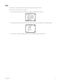
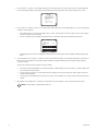
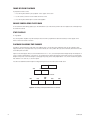
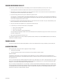
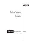
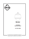
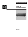
INSTALLATION/OPERATION
®
DX1104-080
Digital Video Recorder
C617M-A (7/04)
Contents
Contents . . . . . . . . . . . . . . . . . . . . . . . . . . . . . . . . . . . . . . . . . . . . . . . . . . . . . . . . . . . . . . . . . . . . . . . . . . . . . . . . . . . . . . . . . . . . . . . . . . . 2
List of Illustrations . . . . . . . . . . . . . . . . . . . . . . . . . . . . . . . . . . . . . . . . . . . . . . . . . . . . . . . . . . . . . . . . . . . . . . . . . . . . . . . . . . . . . . . . . . . 3
List of Tables . . . . . . . . . . . . . . . . . . . . . . . . . . . . . . . . . . . . . . . . . . . . . . . . . . . . . . . . . . . . . . . . . . . . . . . . . . . . . . . . . . . . . . . . . . . . . . . . 3
Important Safety Instructions . . . . . . . . . . . . . . . . . . . . . . . . . . . . . . . . . . . . . . . . . . . . . . . . . . . . . . . . . . . . . . . . . . . . . . . . . . . . . . . . . . . 4
Description . . . . . . . . . . . . . . . . . . . . . . . . . . . . . . . . . . . . . . . . . . . . . . . . . . . . . . . . . . . . . . . . . . . . . . . . . . . . . . . . . . . . . . . . . . . . . . . . . 5
Optional Customer-Supplied Items . . . . . . . . . . . . . . . . . . . . . . . . . . . . . . . . . . . . . . . . . . . . . . . . . . . . . . . . . . . . . . . . . . . . . . . . . . 5
Installation . . . . . . . . . . . . . . . . . . . . . . . . . . . . . . . . . . . . . . . . . . . . . . . . . . . . . . . . . . . . . . . . . . . . . . . . . . . . . . . . . . . . . . . . . . . . . . . . . 6
Programming. . . . . . . . . . . . . . . . . . . . . . . . . . . . . . . . . . . . . . . . . . . . . . . . . . . . . . . . . . . . . . . . . . . . . . . . . . . . . . . . . . . . . . . . . . . . . . . . 8
Camera Menu . . . . . . . . . . . . . . . . . . . . . . . . . . . . . . . . . . . . . . . . . . . . . . . . . . . . . . . . . . . . . . . . . . . . . . . . . . . . . . . . . . . . . . . . . . 9
All Resolution Menu . . . . . . . . . . . . . . . . . . . . . . . . . . . . . . . . . . . . . . . . . . . . . . . . . . . . . . . . . . . . . . . . . . . . . . . . . . . . . . . . . . . . 12
Alarm Output Menu . . . . . . . . . . . . . . . . . . . . . . . . . . . . . . . . . . . . . . . . . . . . . . . . . . . . . . . . . . . . . . . . . . . . . . . . . . . . . . . . . . . . . 13
Time Menu . . . . . . . . . . . . . . . . . . . . . . . . . . . . . . . . . . . . . . . . . . . . . . . . . . . . . . . . . . . . . . . . . . . . . . . . . . . . . . . . . . . . . . . . . . . . 15
Password Menu . . . . . . . . . . . . . . . . . . . . . . . . . . . . . . . . . . . . . . . . . . . . . . . . . . . . . . . . . . . . . . . . . . . . . . . . . . . . . . . . . . . . . . . . 16
Program Update Menu. . . . . . . . . . . . . . . . . . . . . . . . . . . . . . . . . . . . . . . . . . . . . . . . . . . . . . . . . . . . . . . . . . . . . . . . . . . . . . . . . . . 17
Help . . . . . . . . . . . . . . . . . . . . . . . . . . . . . . . . . . . . . . . . . . . . . . . . . . . . . . . . . . . . . . . . . . . . . . . . . . . . . . . . . . . . . . . . . . . . . . . . . 19
Operation . . . . . . . . . . . . . . . . . . . . . . . . . . . . . . . . . . . . . . . . . . . . . . . . . . . . . . . . . . . . . . . . . . . . . . . . . . . . . . . . . . . . . . . . . . . . . . . . .
Viewing Cameras . . . . . . . . . . . . . . . . . . . . . . . . . . . . . . . . . . . . . . . . . . . . . . . . . . . . . . . . . . . . . . . . . . . . . . . . . . . . . . . . . . . . . . .
Recording . . . . . . . . . . . . . . . . . . . . . . . . . . . . . . . . . . . . . . . . . . . . . . . . . . . . . . . . . . . . . . . . . . . . . . . . . . . . . . . . . . . . . . . . . . . . .
Manual Recording. . . . . . . . . . . . . . . . . . . . . . . . . . . . . . . . . . . . . . . . . . . . . . . . . . . . . . . . . . . . . . . . . . . . . . . . . . . . . . . . . .
Automatic Scheduled Recording . . . . . . . . . . . . . . . . . . . . . . . . . . . . . . . . . . . . . . . . . . . . . . . . . . . . . . . . . . . . . . . . . . . . . .
Automatic Event Recording . . . . . . . . . . . . . . . . . . . . . . . . . . . . . . . . . . . . . . . . . . . . . . . . . . . . . . . . . . . . . . . . . . . . . . . . . .
Saving Video . . . . . . . . . . . . . . . . . . . . . . . . . . . . . . . . . . . . . . . . . . . . . . . . . . . . . . . . . . . . . . . . . . . . . . . . . . . . . . . . . . . . . . . . . .
Transferring Data Using a USB Flash Drive. . . . . . . . . . . . . . . . . . . . . . . . . . . . . . . . . . . . . . . . . . . . . . . . . . . . . . . . . . . . . . . . . . .
Playback . . . . . . . . . . . . . . . . . . . . . . . . . . . . . . . . . . . . . . . . . . . . . . . . . . . . . . . . . . . . . . . . . . . . . . . . . . . . . . . . . . . . . . . . . . . . . .
Start Playback . . . . . . . . . . . . . . . . . . . . . . . . . . . . . . . . . . . . . . . . . . . . . . . . . . . . . . . . . . . . . . . . . . . . . . . . . . . . . . . . . . . . .
Search . . . . . . . . . . . . . . . . . . . . . . . . . . . . . . . . . . . . . . . . . . . . . . . . . . . . . . . . . . . . . . . . . . . . . . . . . . . . . . . . . . . . . . . . . . .
Fast Playback . . . . . . . . . . . . . . . . . . . . . . . . . . . . . . . . . . . . . . . . . . . . . . . . . . . . . . . . . . . . . . . . . . . . . . . . . . . . . . . . . . . . .
Pause Playback . . . . . . . . . . . . . . . . . . . . . . . . . . . . . . . . . . . . . . . . . . . . . . . . . . . . . . . . . . . . . . . . . . . . . . . . . . . . . . . . . . . .
Frame-by-Frame Playback. . . . . . . . . . . . . . . . . . . . . . . . . . . . . . . . . . . . . . . . . . . . . . . . . . . . . . . . . . . . . . . . . . . . . . . . . . . .
Change Camera Being Played Back . . . . . . . . . . . . . . . . . . . . . . . . . . . . . . . . . . . . . . . . . . . . . . . . . . . . . . . . . . . . . . . . . . . .
Stop Playback . . . . . . . . . . . . . . . . . . . . . . . . . . . . . . . . . . . . . . . . . . . . . . . . . . . . . . . . . . . . . . . . . . . . . . . . . . . . . . . . . . . . .
Playback Following Time Changes . . . . . . . . . . . . . . . . . . . . . . . . . . . . . . . . . . . . . . . . . . . . . . . . . . . . . . . . . . . . . . . . . . . . .
Viewing Recordings on a PC . . . . . . . . . . . . . . . . . . . . . . . . . . . . . . . . . . . . . . . . . . . . . . . . . . . . . . . . . . . . . . . . . . . . . . . . . . . . . .
Power Failure . . . . . . . . . . . . . . . . . . . . . . . . . . . . . . . . . . . . . . . . . . . . . . . . . . . . . . . . . . . . . . . . . . . . . . . . . . . . . . . . . . . . . . . . . .
Alarm Operation. . . . . . . . . . . . . . . . . . . . . . . . . . . . . . . . . . . . . . . . . . . . . . . . . . . . . . . . . . . . . . . . . . . . . . . . . . . . . . . . . . . . . . . .
Alarm Relay Output Operation . . . . . . . . . . . . . . . . . . . . . . . . . . . . . . . . . . . . . . . . . . . . . . . . . . . . . . . . . . . . . . . . . . . . . . . .
20
20
20
20
20
21
21
21
23
23
23
23
23
24
24
24
24
25
25
25
26
Troubleshooting. . . . . . . . . . . . . . . . . . . . . . . . . . . . . . . . . . . . . . . . . . . . . . . . . . . . . . . . . . . . . . . . . . . . . . . . . . . . . . . . . . . . . . . . . . . . . 27
Specifications . . . . . . . . . . . . . . . . . . . . . . . . . . . . . . . . . . . . . . . . . . . . . . . . . . . . . . . . . . . . . . . . . . . . . . . . . . . . . . . . . . . . . . . . . . . . . .
Electrical/Video. . . . . . . . . . . . . . . . . . . . . . . . . . . . . . . . . . . . . . . . . . . . . . . . . . . . . . . . . . . . . . . . . . . . . . . . . . . . . . . . . . . .
Mechanical . . . . . . . . . . . . . . . . . . . . . . . . . . . . . . . . . . . . . . . . . . . . . . . . . . . . . . . . . . . . . . . . . . . . . . . . . . . . . . . . . . . . . . .
General . . . . . . . . . . . . . . . . . . . . . . . . . . . . . . . . . . . . . . . . . . . . . . . . . . . . . . . . . . . . . . . . . . . . . . . . . . . . . . . . . . . . . . . . . .
Regulatory Notices . . . . . . . . . . . . . . . . . . . . . . . . . . . . . . . . . . . . . . . . . . . . . . . . . . . . . . . . . . . . . . . . . . . . . . . . . . . . . . . . .
2
28
28
28
28
29
C617M-A 8/04
List of Illustrations
1
2
3
4
DX1100 Series DVR Front Panel . . . . . . . . . . . . . . . . . . . . . . . . . . . . . . . . . . . . . . . . . . . . . . . . . . . . . . . . . . . . . . . . . . . . . . . . . . 5
DX1100 Series DVR Installation . . . . . . . . . . . . . . . . . . . . . . . . . . . . . . . . . . . . . . . . . . . . . . . . . . . . . . . . . . . . . . . . . . . . . . . . . . 6
Menu Tree . . . . . . . . . . . . . . . . . . . . . . . . . . . . . . . . . . . . . . . . . . . . . . . . . . . . . . . . . . . . . . . . . . . . . . . . . . . . . . . . . . . . . . . . . . 8
Recording and Playback When Hour Is Set Back . . . . . . . . . . . . . . . . . . . . . . . . . . . . . . . . . . . . . . . . . . . . . . . . . . . . . . . . . . . . 24
List of Tables
A
B
C617M-A 8/04
Video Coaxial Cable Requirements . . . . . . . . . . . . . . . . . . . . . . . . . . . . . . . . . . . . . . . . . . . . . . . . . . . . . . . . . . . . . . . . . . . . . . . 7
Maximum Frames per Second. . . . . . . . . . . . . . . . . . . . . . . . . . . . . . . . . . . . . . . . . . . . . . . . . . . . . . . . . . . . . . . . . . . . . . . . . . . 10
3
Important Safety Instructions
Observe the following warnings before installing and using this product:
1. Read these instructions.
2. Keep these instructions.
3. Heed all warnings.
4. Follow all instructions.
5. Do not use this apparatus near water.
6. Clean only with dry cloth.
7. Do not block any ventilation openings. Install in accordance with the manufacturer’s instructions.
8. Do not install near any heat sources such as radiators, heat registers, stoves, or other apparatus (including amplifiers) that produce heat.
9. Do not defeat the safety purpose of the polarized or grounding-type plug. A polarized plug has two blades with one wider than the other. A
grounding type plug has two blades and a third grounding prong. The wide blade or the third prong are provided for your safety. If the
provided plug does not fit into your outlet, consult an electrician for replacement of the obsolete outlet.
10. Protect the power cord from being walked on or pinched particularly at plugs, convenience receptacles, and the point where they exit from
the apparatus.
11. Only use attachments/accessories specified by the manufacturer.
12. Use only with the cart, stand, tripod, bracket, or table specified by the manufacturer, or sold with the apparatus. When a cart is used, use
caution when moving the cart/apparatus combination to avoid injury from tip-over.
13. Unplug this apparatus during lightning storms or when unused for long periods of time.
14. Refer all servicing to qualified service personnel. Servicing is required when the apparatus has been damaged in any way, such as powersupply cord or plug is damaged, liquid has been spilled or objects have fallen into the apparatus, the apparatus has been exposed to rain or
moisture, does not operate normally, or has been dropped.
15. Apparatus shall not be exposed to dripping or splashing and that no objects filled with liquids, such as vases shall be placed on the
apparatus.
16. WARNING: To reduce the risk of fire or electric shock, do not expose this apparatus to rain or moisture.
17. Installation should be done only by qualified service personnel and conform to all local codes.
18. The socket-outlet shall be installed near the equipment and shall be easily accessible.
CAUTION: These servicing instructions are for use by qualified service personnel only. To reduce the risk of electric shock do not perform any
servicing other than that contained in the operating instructions unless you are qualified to do so.
CAUTION: Danger of explosion if battery is incorrectly replaced. Replace only with the same or equivalent type. Dispose of used batteries
according to the instructions provided by the battery manufacturer.
Only use replacement parts recommended by Pelco.
The product and/or manual may bear the following marks:
This symbol indicates that dangerous voltage constituting a risk of electric shock is
present within this unit.
This symbol indicates that there are important operating and maintenance instructions
in the literature accompanying this unit.
4
CAUTION:
RISK OF ELECTRIC SHOCK.
DO NOT OPEN.
C617M-A 8/04
Description
The DX1104-080 digital video recorder (DVR) is a compact recorder that can store and play back images from four cameras and audio from one
camera. The DVR can be placed on a shelf or desktop for easy access to the front panel controls for operation and programming.
Live video from all four cameras can be viewed while recording. Recording can be done continuously or for a scheduled time in a 24-hour period.
Each camera has its own alarm input for alarm recording.
An 80 GB hard drive generally allows continuous recording up to four weeks under the most common recording conditions. Recording time will
vary depending on image size, number of cameras recorded, resolution selection, and record rate.
Recording can be stopped at any time to play back video. Search functions during playback allow frame-by-frame viewing, fast playback, and
playback of alarm events.
The DVR uses proprietary compression algorithms to prevent alteration of the video image, as well as password protection to guard against
unauthorized or unintentional recording or playback.
The DX1104-080 lets you load the latest software version (available from Pelco’s web site) into the DVR via a USB flash drive that is supplied
with the DVR. The USB flash drive can also be used to save recorded video and audio from the DVR to a PC.
Power
Record
1
2
3
4
5
6
7
8
9
0
Stop
Search
Play/Pause
Function
Search
1100 SERIES
DIGITAL VIDEO RECORDER
Figure 1. DX1100 Series DVR Front Panel
OPTIONAL CUSTOMER-SUPPLIED ITEMS
•
A preamplified microphone is needed to record audio.
•
PC with the following minimum requirements:
C617M-A 8/04
•
Windows® 98, 2000, or XP operating system
•
Pentium® CPU (128 MB SDRAM and 400 MHz processing speed)
•
Matrox G400™ video card (16 MB memory)
•
Sound Blaster®-compatible card
5
Installation
The following parts are supplied:
1
DX1100 Series DVR
1
230 VAC power cord adapter
1
USB extension cable (for connecting non-adjacent equipment)
1
USB flash drive (USB 1.1 compliant) (Supplied for a limited time only)
�
�
�
FLASH DRIVE
��
POWER
INPUT
CAMERA
1
2
3
4
OUTPUT
VIDEO
ON
AUDIO
6e 6d 7a
IN
ALARM
USB
SENSOR
NTSC
OUT
1 GND 2 GND 3 GND 4 GND
OFF
AC IN
7c
7b
POWER
CONNECTION
PAL
12 VDC LAMP
6c
12 VDC
BUZZER
6b
� �
6a
�
Figure 2. DX1100 Series DVR Installation
6
C617M-A 8/04
WARNING: Adequate ventilation is required for proper operation of the DVR. Allow two inches of space above the unit and on each
side for air circulation.
1. Connect cameras to the CAMERA INPUT connectors (BNC) on the rear of the DVR. Refer to Table A for video coaxial cable distances.
2. Connect a monitor to one of the VIDEO OUTPUT connectors (BNC) on the rear of the DVR. Refer to Table A for video coaxial cable distances.
3. To save data from the DVR, use the USB flash drive or connect a peripheral recording device to the remaining VIDEO OUTPUT connector
(BNC) on the rear of the DVR. Refer to Table A for video coaxial cable distances.
Table A. Video Coaxial Cable Requirements
Cable Type*
RG59/U
RG6/U
RG11/U
Maximum Distance
750 ft (229 m)
1,000 ft (305 m)
1,500 ft (457 m)
*Minimum cable requirements:
75 ohms impedance
All-copper center conductor
All-copper braided shield with 95% braid coverage
4. If audio is desired, connect a preamplified microphone to the AUDIO IN jack on the rear of the DVR.
NOTE: Before using the DX1104-080’s audio recording feature, consult your location’s applicable laws regarding audio
surveillance.
5. To save audio from the DVR, use the USB flash drive or connect a peripheral recording device to the AUDIO OUT jack on the rear of the DVR.
6. Connect alarm inputs and alarm relay output as follows:
a.
Inputs – Connect wiring (not supplied) to your alarms (not supplied). Two wires are required for each alarm. You can have one alarm
for each camera.
b.
Output – Connect wiring (not supplied) to a 12 VDC light or buzzer (not supplied). Two wires are required.
c.
Bring the alarm input and output wiring to the back of the DVR and thread the wiring through the Induced Voltage Protector (supplied).
Loop the wiring over the voltage protector and thread it through the voltage protector a second time.
d.
Connect the alarm input wires to the SENSOR connectors.
e.
Connect the light or buzzer to the ALARM output connectors.
7. Connect the recorder to power.
a.
Place the NTSC/PAL switch in the proper mode.
b.
If applicable, connect the 230 VAC adapter to the end of the power cord. Plug in the power cord.
c.
Turn on the DVR. When the recorder is turned on for the first time, the Help screens will appear on the monitor. To bypass the Help
screens, press the Play/Pause button.
8. Turn on the cameras and monitor. The DVR begins recording the cameras.
IMPORTANT: If you have any unused camera inputs, the video appears washed out. The degree of washout depends on how
many inputs have no cameras connected to them. If only one camera is connected, the video is completely washed out. When you
program the DVR (step 11), you must turn off any unused camera inputs. Video will then appear normal.
9. Go to Time Menu in the Programming section and set the time and date.
10. Initialize the DVR. Refer to the instructions on the separate sheet included with this manual.
This is a necessary step as the DVR may not operate properly during playback and search operation if there are conflicts in the date and
time.
11. Proceed to the Programming section to set up the recording parameters and enter a password (optional).
C617M-A 8/04
7
Programming
Programming allows you to configure camera, audio, and alarm operation; set the system date and time; define a password; and update the
program.
CAMERA/AUDIO
On
Camera 1:
On
Camera 2:
On
Camera 3:
On
Camera 4:
On
Preview:
fps (Frame Per Second): 01
Audio:
On
Quit
CAMERA 1*
AUTOMATIC RECORDING TIME CHANGE
Camera operation:
On
Automatic Recording:
On
Automatic recording time change
Resolution
Recording starting time: 00 Quit
Recording ending time: 24
Event recording starting time: 00
Event recording ending time: 24
Event recording duration (sec.): 030
Quit
*Same menu for cameras 2-4.
RESOLUTION
Lowest resolution:
Off
Low resolution:
Off
Standard resolution:
On
High resolution:
Off
Highest resolution:
Off
RESOLUTION
Quit
SETUP MENU
Camera/Audio
All Resolution
Alarm Output
Time
Password
Program Update
Exit
Help: ON
ALARM OUTPUT
Enable Alarm Output:
00
Disable Alarm Output:
24
Lowest resolution:
Off
Low resolution:
Off
Standard resolution:
On
High resolution:
Off
Highest resolution:
Off
Quit
Automatically Enable
On
Alarm Output:
Quit
TIME
TIME
Year/Month/Date/Hour/Minute
On
Daylight Savings Time:
Quit
OR
Year/Month/Date/Hour/Minute
On
Daylight Savings Time:
-Starting Time: Month/Date/Hour
-Ending Time: Month/Date/Hour
Quit
PASSWORD
User level password protection: Off
Password change
Quit
PROGRAM UPDATE
Current Version:
Next Version:
Update
Quit
Figure 3. Menu Tree
8
C617M-A 8/04
CAMERA MENU
Use this menu to define the following:
•
Which cameras the DVR will record
•
Whether starting and stopping of recording will be done manually or automatically
•
What the record rate (frames per second) will be
•
What the recording resolution (low to high) will be
•
Whether live video can be viewed in record mode
•
Starting and stopping times for scheduled recording
•
Whether audio recording will be on or off
TIP: You can return to the previous menu at any time by pressing the Stop button.
Skip steps 1 and 2 if you are already in the Setup Menu.
1. Press and hold the Function button. The Function Key List appears. Keep holding the Function button.
FUNCTION KEY LIST
0 : Setup
1 : Camera 1 recording/stop
2 : Camera 2 recording/stop
3 : Camera 3 recording/stop
4 : Camera 4 recording/stop
5 : All the cameras recording
6 : All the cameras stop
: Alarm On
: Alarm Off
2. Press and release the 0 button, and then release the Function button. Enter the password if requested. The Setup Menu appears.
SETUP MENU
Camera/Audio
All Resolution
Alarm Output
Time
Password
Program Update
Exit
Help: ON
3. Use the Search (<</>>) buttons to move around within the menu. Highlight Camera/Audio and then press the Play/Pause button to select.
The Camera menu appears.
CAMERA/AUDIO
On
Camera 1:
On
Camera 2:
On
Camera 3:
On
Camera 4:
On
Preview:
fps (Frame Per Second): 01
Audio:
On
Quit
4. If the Preview field shows On, live video from the cameras will appear on the monitor while the DVR is recording or is in recording standby
mode (not recording).
If the Preview field shows Off, live video will not be shown.
To change the Preview status, use the Search (<</>>) buttons to highlight Preview, and then press the Play/Pause button to toggle between
On and Off.
C617M-A 8/04
9
5. The fps (Frame Per Second) field shows the recording rate for all cameras.
To change the fps, use the Search (<</>>) buttons to highlight fps, and then use the number keypad to enter the frames per second. The
maximum frames per second is determined by the number of cameras being recorded and whether the Preview feature is on or off. Refer to
Table B for the maximum frames per second.
Table B. Maximum Frames per Second
Cameras
1
2
3
4
Preview On
15
5
3
2
Preview Off
30
7
5
3
6. If the Audio field shows ON, audio from the cameras will be recorded while the DVR is recording. If the field shows OFF, audio will not be
recorded (even though video may be).
To change audio recording, use the Search (<</>>) buttons to highlight Audio, and then press the Play/Pause button to toggle between On
and Off.
7. To configure any of the four cameras, use the Search (<</>>) buttons to highlight the camera number, and then press the Play/Pause button.
The menu for that camera appears.
CAMERA 1*
Camera operation:
On
Automatic Recording:
On
Automatic recording time change
Resolution
Quit
*Same menu for cameras 2-4.
8. CAMERA OPERATION
Use the Search (<</>>) buttons to highlight Camera Operation, and then press the Play/Pause button to toggle between On or Off. On
means the DVR will record video for that channel, and Off means it will not record video, even if a camera is connected.
IMPORTANT NOTE: If camera inputs are not used, make sure Camera Operation is OFF. Video washout occurs if unused inputs
are left on. The degree of washout depends on how many inputs have no cameras connected to them. The most severe case is
when all inputs are turned on but only one camera is connected; in this case the video is completely washed out.
9. AUTOMATIC RECORDING
Use the Search (<</>>) buttons to highlight Automatic Recording, and then press the Play/Pause button to toggle between On or Off. On
means the DVR will record automatically during the times you will select in the following steps. Off means you will manually turn the
recorder on and off.
10. AUTOMATIC RECORDING TIME CHANGE
Use the Search (<</>>) buttons to highlight Automatic Recording Time Change, and then press the Play/Pause button to select. The Automatic Recording Time Change menu appears.
AUTOMATIC RECORDING TIME CHANGE
Recording starting time: 00
Recording ending time: 24
Quit
Event recording starting time: 00
Event recording ending time: 24
Event recording duration (sec.): 030
10
C617M-A 8/04
11. Use the Search (<</>>) buttons to highlight each field in the menu.
Recording Times
The recorder will record continuously between the specified times. Use the number buttons to enter the hour of the starting time and ending time. Enter two digits. Enter the hours in 24-hour format. For example, enter 08 for 8 a.m. and 15 for 3 p.m. For 24-hour recording, enter
a start time of 00 and an ending time of 24. For no recording, enter a start time of 24 and an end time of 00.
Event Recording Times
Event recording means the recorder will only record if there are alarms during the specified time period. Use the number buttons to enter
the hour of the starting time and ending time. Enter two digits. Enter the hours in 24-hour format. For example, enter 08 for 8 a.m. and 15
for 3 p.m. For 24-hour recording, enter a start time of 00 and an ending time of 24. For no recording, enter a start time of 24 and an end time
of 00.
NOTE: Recording and event recording times should be set for different time periods. For example, you may want to record continuously in the daytime when there is a lot of activity, but record only alarms at night.
Event Recording Duration
This is the time the recorder will continue recording after the alarm goes away. The time can be set from 0 to 200 seconds.
Recording Bar
At the bottom of the screen is a bar that shows when recording will occur. Red is for continuous recording, blue is for event recording, and
white is for no recording. If you overlap the continuous and event recording times, the bar will be red.
Quit
When you finish entering the times, use the Search (<</>>) buttons to highlight Quit, and then press the Play/Pause button to select. The
Camera Number menu appears.
12. RESOLUTION
In this step the camera’s resolution is set. You can set each camera’s resolution individually, allowing you to use different resolutions for
the different cameras. Or you can set the resolution for all cameras at one time; in this case, the resolution will be the same for all cameras.
To set each camera’s resolution individually, follow the steps below.
If you want to use the same resolution for all cameras, skip this step and proceed to step 13 to finish the individual setup of
cameras. Then set the resolution for all cameras in the All Resolution menu (next section).
a.
Use the Search (<</>>) buttons to highlight Resolution, and then press the Play/Pause button to select. The Resolution menu appears.
RESOLUTION
Lowest resolution:
Off
Low resolution:
Off
Standard resolution:
On
High resolution:
Off
Highest resolution:
Off
Quit
b.
Use the Search (<</>>) buttons to highlight a resolution, and then press the Play/Pause button. When one resolution is turned On, all
others are set to Off.
c.
Use the Search (<</>>) buttons to highlight Quit, and then press the Play/Pause button to select. The Camera Number menu appears.
d.
Use the Search (<</>>) buttons to highlight Quit, and then press the Play/Pause button to select. The Camera menu appears.
13. Repeat steps 7-12 to configure other cameras. When you finish configuring all cameras, press the Stop button as many times as necessary
to return to the Setup Menu. Highlight another menu item in the Setup Menu and then press the Play/Pause button to select it, or highlight
Exit and then press the Play/Pause button to end the programming session.
C617M-A 8/04
11
ALL RESOLUTION MENU
Use this menu to set the resolution for all cameras. If you want to use different resolutions for the cameras, set the resolutions in the Camera
menu (previous section).
NOTES: Setting the resolution in this menu will overwrite all camera resolution settings made in the individual camera settings (step 12
of previous section).
Higher resolutions require more disk storage space, reducing the recording time; lower resolutions need less disk space, increasing the
recording time.
Skip steps 1 and 2 if you are already in the Setup Menu.
1. Press and hold the Function button. The Function Key List appears. Keep holding the Function button.
FUNCTION KEY LIST
0 : Setup
1 : Camera 1 recording/stop
2 : Camera 2 recording/stop
3 : Camera 3 recording/stop
4 : Camera 4 recording/stop
5 : All the cameras recording
6 : All the cameras stop
: Alarm On
: Alarm Off
2. Press and release the 0 button, and then release the Function button. Enter the password if requested. The Setup Menu appears.
SETUP MENU
Camera/Audio
All Resolution
Alarm Output
Time
Password
Program Update
Exit
Help: ON
3. Use the Search (<</>>) buttons to highlight All Resolution, and then press the Play/Pause button to select. The All Resolution menu
appears.
RESOLUTION
Lowest resolution:
Off
Low resolution:
Off
Standard resolution:
On
High resolution:
Off
Highest resolution:
Off
Quit
4. Use the Search (<</>>) buttons to highlight a resolution, and then press the Play/Pause button. When one resolution is turned On, all others
are set Off.
5. Use the Search (<</>>) buttons to highlight Quit, and then press the Play/Pause button to select. The Setup Menu appears.
TIP: Pressing the Stop button also returns you to the Setup Menu.
6. Use the Search (<</>>) buttons to highlight another menu item in the Setup Menu and then press the Play/Pause button to select it, or
highlight Exit and then press the Play/Pause button to end the programming session.
12
C617M-A 8/04
ALARM OUTPUT MENU
The ALARM output on the rear panel is a single-pole, normally open, latching, dry contact. This output can be used to notify you if there has been
an alarm event that might require review. The alarm output can be enabled or disabled (armed/disarmed) manually, or it can be programmed to
enable (arm) or disable (disarm) at the same time automatically every day.
If the output is enabled and an alarm input is activated, the output relay will latch closed after a 20-second delay and will remain closed until it
is manually disabled. The 20-second delay allows you to enter your premises and disable the alarm output before it is activated.
The alarm output menu is used to set up automatic arming and disarming of the relay at specified times each day. (For manual operation, refer to
Alarm Relay Output Operation in the Operation section.) This feature may be used in conjunction with the event recording capabilities of the
DX1100 to notify you that an alarm event was recorded.
NOTE: The alarm output programming does not affect recording. It only affects the operation of the alarm output relay. For event (alarm)
recording, refer to Recording in the Operation section.
Application example:
A company has a rear door that is not to be opened for any reason between 5 p.m. and 7 a.m. During the day, the area around this door is
recorded continuously, but to conserve disk space, the area is only recorded at night if the door is opened. The owner does not want to review the
video unless the door was opened after hours.
In this case, the alarm output would be programmed to enable at 5 p.m. and disable at 7 a.m. The DX1100 would also be programmed for automatic (continuous) recording from 7 a.m. to 5 p.m. and event recording from 5 p.m. to 7 a.m. (refer to Camera Menu in the Programming section).
At 5 p.m. continuous recording would cease. If an alarm input is activated, the DVR would immediately begin recording the associated camera.
The relay would latch closed after the 20-second delay. When the owner returned in the morning, a light attached to the relay output would be
on, indicating that there was an alarm during the night. A search for recorded video starting at 5 p.m. would immediately take you to the first
alarm event. All other events could be reviewed in sequence.
To program the relay for automatic arming/disarming:
Skip steps 1 and 2 if you are already in the Setup Menu.
1. Press and hold the Function button. The Function Key List appears. Keep holding the Function button.
FUNCTION KEY LIST
0 : Setup
1 : Camera 1 recording/stop
2 : Camera 2 recording/stop
3 : Camera 3 recording/stop
4 : Camera 4 recording/stop
5 : All the cameras recording
6 : All the cameras stop
: Alarm On
: Alarm Off
2. Press and release the 0 button, and then release the Function button. Enter the password if requested. The Setup Menu appears.
SETUP MENU
Camera/Audio
All Resolution
Alarm Output
Time
Password
Program Update
Exit
Help: ON
C617M-A 8/04
13
3. Use the Search (<</>>) buttons to move around within the menu. Highlight Alarm Output and press the Play/Pause button to select. The
Alarm Output menu appears.
ALARM OUTPUT
Enable Alarm Output:
00
Disable Alarm Output:
24
Automatically Enable
Alarm Output:
On
Quit
4. Use the Search (<</>>) buttons to highlight the fields for starting and ending times. When you highlight a field, use the number buttons to
enter the time. The starting and ending times refer to the hour. Enter two digits. Enter the hours in 24-hour format. For example, enter 08 for
8 a.m. and 15 for 3 p.m.
At the bottom of the screen is a bar that shows the hours when the alarm output will be enabled. Red means enabled and white means
disabled.
5. Use the Search (<</>>) buttons to highlight Automatically Enable Alarm Output, and then press the Play/Pause button to toggle between
On or Off.
6. When you finish, use the Search (<</>>) buttons to highlight Quit, and then press the Play/Pause button to select. The Setup Menu appears.
TIP: Pressing the Stop button also returns you to the Setup Menu.
7. Use the Search (<</>>) buttons to highlight another menu item in the Setup Menu and then press the Play/Pause button to select it, or
highlight Exit and then press the Play/Pause button to end the programming session.
14
C617M-A 8/04
TIME MENU
The DVR uses the time and date to index video on the hard disk drive so you can find it later. Changing the time can cause the DVR to work
improperly when you try to play back video. If you set the hour ahead, this is not a problem. But if you set the hour back, there will be more than
one recording at the same time. Therefore, you should refrain from making frequent changes as this will complicate searching by time and date.
For more information, refer to Playback Following Time Changes in the Operation section.
To set the system time and date:
Skip steps 1 and 2 if you are already in the Setup Menu.
1. Press and hold the Function button. The Function Key List appears. Keep holding the Function button.
FUNCTION KEY LIST
0 : Setup
1 : Camera 1 recording/stop
2 : Camera 2 recording/stop
3 : Camera 3 recording/stop
4 : Camera 4 recording/stop
5 : All the cameras recording
6 : All the cameras stop
: Alarm On
: Alarm Off
2. Press and release the 0 button, and then release the Function button. Enter the password if requested. The Setup Menu appears.
SETUP MENU
Camera/Audio
All Resolution
Alarm Output
Time
Password
Program Update
Exit
Help: ON
3. Use the Search (<</>>) buttons to move around within the menu. Highlight Time and press the Play/Pause button to select. The Time menu
appears.
TIME
TIME
Year/Month/Date/Hour/Minute
Daylight Savings Time:
Quit
On
OR
Year/Month/Date/Hour/Minute
On
Daylight Savings Time:
-Starting Time: Month/Date/Hour
-Ending Time: Month/Date/Hour
Quit
4. There are five fields for entering the date and time. The fields, from left to right, are for the year, month, day, hour, and minute. Use the
Search (<</>>) buttons to move between the fields. In each field enter two digits. For numbers below 10, enter a 0 as the first digit. Enter
the hour in 24-hour format; for example, 08 is 8 a.m. and 15 is 3 p.m.
5. Use the Search (<</>>) buttons to highlight Daylight Savings Time, and then press the Play/Pause button to toggle between On or Off. If
your unit is set for PAL operation, also enter the starting and ending times.
6. Use the Search (<</>>) buttons to highlight Quit, and then press the Play/Pause button to select. The Setup Menu appears.
TIP: Pressing the Stop button also returns you to the Setup Menu.
7. Use the Search (<</>>) buttons to highlight another menu item in the Setup Menu and then press the Play/Pause button to select it, or
highlight Exit and then press the Play/Pause button to end the programming session.
C617M-A 8/04
15
PASSWORD MENU
Use this menu to change the password (optional).
Skip steps 1 and 2 if you are already in the Setup Menu.
1. Press and hold the Function button. The Function Key List appears. Keep holding the Function button.
FUNCTION KEY LIST
0 : Setup
1 : Camera 1 recording/stop
2 : Camera 2 recording/stop
3 : Camera 3 recording/stop
4 : Camera 4 recording/stop
5 : All the cameras recording
6 : All the cameras stop
: Alarm On
: Alarm Off
2. Press and release the 0 button, and then release the Function button. Enter the password if requested. The Setup Menu appears.
SETUP MENU
Camera/Audio
All Resolution
Alarm Output
Time
Password
Program Update
Exit
Help: ON
3. Use the Search (<</>>) buttons to move around within the menu. Highlight Password and press the Play/Pause button to select.
The Password menu appears.
PASSWORD
User level password protection: Off
Password change
Quit
4. Use the Search (<</>>) buttons to highlight User Level Password Protection, and then press the Play/Pause button to toggle between
On or Off.
ENTER PASSWORD
“Input your password.”
5. Use the Search (<</>>) buttons to highlight Password Change, and then press the Play/Pause button to select. The Enter Password screen
appears.
6. The DVR ships from the factory with a password of 0000. Enter four numbers for a new password.
7. You will be prompted to verify your password by entering it a second time. If the two passwords agree, “Registered” appears on the screen
and then the Password menu reappears. If the passwords do not agree, “Registration Cancelled” appears on the screen and then the
Password menu reappears.
8. Use the Search (<</>>) buttons to highlight Quit, and then press the Play/Pause button to select. The Setup Menu appears.
TIP: Pressing the Stop button also returns you to the Setup Menu.
9. Use the Search (<</>>) buttons to highlight another menu item in the Setup Menu and then press the Play/Pause button to select it, or
highlight Exit and then press the Play/Pause button to end the programming session.
16
C617M-A 8/04
PROGRAM UPDATE MENU
Use this menu to load a newer version of software into your unit. This menu also shows the current version of software that is in your DVR.
NOTE: To perform this update, you will need a USB flash drive (32 MB minimum and FAT or FAT32 format) and a PC to access the Pelco
Internet web site (www.pelco.com).
1. Load the new version of software from the Pelco web site onto the USB flash drive. Contact Pelco Technical Support at 1-800-289-9100 if
you need assistance.
2. Refer to Figure 2. Once the new software is on the USB flash drive, insert the USB flash drive into the USB port on the DVR.
3. (Skip this step and step 4 if you are already in the Setup Menu.) Press and hold the Function button. The Function Key List appears. Keep
holding the Function button.
FUNCTION KEY LIST
0 : Setup
1 : Camera 1 recording/stop
2 : Camera 2 recording/stop
3 : Camera 3 recording/stop
4 : Camera 4 recording/stop
5 : All the cameras recording
6 : All the cameras stop
: Alarm On
: Alarm Off
4. Press and release the 0 button, and then release the Function button. Enter the password if requested. The Setup Menu appears.
SETUP MENU
Camera/Audio
All Resolution
Alarm Output
Time
Password
Program Update
Exit
Help: ON
5. Use the Search (<</>>) buttons to move around within the menu. Highlight Program Update and press the Play/Pause button to select. The
Program Update screen appears unless one of the following conditions exists.
•
If there is no update file in the USB flash drive, the error message “File name error” appears and you will be returned to the Setup
Menu.
•
If the USB flash drive is not inserted in the DVR, the error message “Device not found” appears and you will be returned to the Setup
Menu.
The Program Update screen shows the current software version in the DVR and the new software version that will be updated from the
USB flash drive.
PROGRAM UPDATE
Current Version:
Next Version:
Update
C617M-A 8/04
Quit
17
6. Use the Search (<</>>) buttons to highlight Update and then press the Play/Pause button to select. (If you do not want to update your
program, highlight Quit and press the Play/Pause button.) The update starts and the Program Update Processing screen appears, which
shows the progress of the update.
PROGRAM UPDATE
“Program update processing”
10%
A defect in the USB flash drive or in the file can cause an error, in which case the error message “Error on program update process” appears
and you will be returned to the Setup Menu.
7. When the update is finished, the message “Program update completed successfully” appears.
PROGRAM UPDATE
“Program update completed
successfully”
8. You must reboot the unit to operate it with the new software. It takes about 10 seconds to reboot the first time following the software
update. This lets the DVR safely back up the new software.
If you fail to reboot the unit, it will operate with the previous software version.
18
C617M-A 8/04
HELP
If the Help function is enabled, the Help screens appear on the monitor whenever power is turned on.
Skip steps 1 and 2 if you are already in the Setup Menu.
1. Press and hold the Function button. The Function Key List appears. Keep holding the Function button.
FUNCTION KEY LIST
0 : Setup
1 : Camera 1 recording/stop
2 : Camera 2 recording/stop
3 : Camera 3 recording/stop
4 : Camera 4 recording/stop
5 : All the cameras recording
6 : All the cameras stop
: Alarm On
: Alarm Off
2. Press and release the 0 button, and then release the Function button. Enter the password if requested. The Setup Menu appears.
SETUP MENU
Camera/Audio
All Resolution
Alarm Output
Time
Password
Program Update
Exit
Help: ON
3. Use the Search (<</>>) buttons to highlight Help, and then press the Play/Pause button to select ON or OFF.
C617M-A 8/04
19
Operation
The Record LED on the front panel indicates what the DVR is doing.
Recording:
Red (blinking)
Playback:
Green (steady)
Fast Playback:
Green (blinking)
Alarm Event Recording Enabled:
Yellow (steady)
Stop:
Off
VIEWING CAMERAS
If the Preview feature in the Camera menu is On, you can view live video on the monitor. Video is displayed full-screen only if one camera is
turned on. If more than one camera is turned on, video is shown in a quad view.
If the Preview feature in the Camera menu is Off, you cannot view live video on the monitor.
RECORDING
MANUAL RECORDING
NOTE: Automatic Recording in the Camera menu must be OFF.
1. Press and hold the Function button. The Function Key list appears. Keep holding the Function button.
FUNCTION KEY LIST
0 : Setup
1 : Camera 1 recording/stop
2 : Camera 2 recording/stop
3 : Camera 3 recording/stop
4 : Camera 4 recording/stop
5 : All the cameras recording
6 : All the cameras stop
: Alarm On
: Alarm Off
2. Press buttons 1-6 to start or stop recording. Buttons 1-4 are toggle switches: if a camera is recording, pressing a button will stop recording;
if a camera is not recording; pressing a button will start recording.
3. Release the Function button. Cameras set to record will record continuously until you repeat steps 1 and 2 and stop recording.
AUTOMATIC SCHEDULED RECORDING
Scheduled recording allows you to program the DVR to turn on and off at specified times each day. This way you record only when you need to
and can conserve hard disk drive space. When the hard disk drive is full, the DVR starts to overwrite the oldest data.
NOTE: Turning off certain cameras does not save the video from those cameras. All turning off certain cameras does is provide more
disk space to record other cameras. When the hard disk drive is full, the DVR will start overwriting the oldest video recorded.
Refer to Camera Menu in the Programming section to set the start and stop times for recording.
If you need to stop recording a camera before the programmed end time, you must go back into the programming menus and turn off the automatic recording for that camera.
20
C617M-A 8/04
AUTOMATIC EVENT RECORDING
Event recording allows you to program the DVR to record only when an alarm input is activated. The DVR will record for as long as the alarm
input is active. After the alarm goes away, the DVR will continue to record for the programmed time. Event recording allows you to conserve even
more hard disk drive space than scheduled recording. When the hard disk drive is full, the DVR starts to overwrite the oldest data.
Refer to Camera Menu in the Programming section to set the start and stop times for recording.
If you need to stop recording a camera before the programmed end time, you must go back into the programming menus and turn off the automatic recording for that camera.
Recording example:
A company has a rear door that is not to be opened for any reason between 5 p.m. and 7 a.m. During the day, the area around this door is
recorded continuously (scheduled recording), but to conserve disk space, the area is only recorded at night if the door is opened (event recording).
In this case, the recorder would be programmed for scheduled (continuous) recording from 7 a.m. to 5 p.m. and event recording from 5 p.m. to
7 a.m. (refer to Camera Menu in the Programming section).
SAVING VIDEO
When the hard disk drive is full, the DVR starts to overwrite the oldest data. Data should be backed up on a regular basis to ensure that important video is not lost.
NOTE: Turning off certain cameras does not save the video from those cameras. All turning off certain cameras does is provide more
disk space to record other cameras. When the hard disk drive is full, the DVR will start overwriting the oldest video recorded.
To save video:
1. Connect a peripheral recording device, such as a VCR or video printer, to the VIDEO OUTPUT connector on the rear of the DVR.
2. Turn on the peripheral recording device. If the DVR is in the record mode, the video also will be recorded on the peripheral device. If the
DVR is in the playback mode, the video will be recorded on the peripheral device.
TRANSFERRING DATA USING A USB FLASH DRIVE
WARNING: The transfer procedure that follows will format the USB flash drive (FAT or FAT32 format, which are the only formats the
USB flash drive accepts). Formatting erases existing data on the USB flash drive. It cannot be recovered. Transfer to another medium any
data on the USB flash drive that you do not want to lose.
The following procedure transfers data onto the USB flash drive. (The amount is limited. For example, with audio enabled and recording four
channels at a size of 4 KB and at 1 fps, you could transfer roughly 25 minutes onto a 32 MB USB flash drive. This is an estimate only and not an
implied or expressed guarantee of actual storage. The amount you can store on the USB flash drive may vary based on video sources.)
NOTE: The DX1140-080 comes with a USB flash drive. If you are using a different USB flash drive, make sure it meets the following
requirements:
•
•
•
USB 1.1 compliant
Only offered as a storage device—no additional software features (such as security, mail, and others)
32, 64, 128, or 256 MB
Do the following:
1. Press the Play/Pause button.
2. Enter the password if requested. The Play screen appears.
PLAY
From
to
/
/
/
/
Data search is possible by Year/month/date.
CH
Camera
Playing time
Playback
C617M-A 8/04
Audio:
Backup
21
3. Use the Search (<</>>) buttons to select Backup and then press the Play/Pause button. (You do not have to choose a camera number and
time.) The following confirmation screen appears, warning that data on the USB flash drive will be erased and cannot be recovered.
BACKUP
The current file in USB
memory stick will be erased
while backup process.
The erased file cannot be
recovered.
Will you continue?
YES
NO
4. Use the Search (<</>>) buttons to select Yes to continue (or No to abort), and then press the Play/Pause button. If Yes, then a “Reading disk
information” message appears.
•
If the USB flash drive is not inserted in the DVR or there is an error on the flash drive, the error message “Device not found” appears
and you are returned to the Play window.
•
If there is no problem, you are returned to the Backup menu, as shown below, when the disk information has been read.
BACKUP
From
/
/
to /
/
Available Capacity:
MByte
Start Time
End Time
Download
•
Quit
The Backup menu shows the first recording date and time and the last recording time, with the available recording capacity directly
below.
5. To start the backup, use the Search (<</>>) buttons to enter the date and time to backup, select Download, and then press the Play/Pause
button. If there are no problems, the percentage of backup completed is displayed. When finished, the message “Backup completed
successfully” appears.
However, the following messages can appear if there are problems:
•
If the amount of data to be backed up is more than the flash drive’s available capacity, the error message “Less capacity” appears and
you are returned to the Play window.
•
If the time range you selected is out of the range that was recorded, the error message “Wrong time setting” appears and you are
returned to the Play window.
•
If a problem occurs during backup processing, the error message “Error on backup process” appears and you are returned to the Play
window.
6. When backup to the USB flash drive is completed, insert the flash drive into the USB port on your PC and transfer the file to the PC.
NOTE: Viewing software is exported with the video clip.
22
C617M-A 8/04
PLAYBACK
START PLAYBACK
To begin playback:
1. Press the Play/Pause button.
2. Enter the password if requested.
3. The Play window appears.
PLAY
From 2003 /01/01
to 2003/03/03
Data search is possible by Year/Month/Date.
Camera
Playing time
2003 02
Playback
3CH Audio:
05
09
00
Backup
4. Press a number button (1-4) to select the camera to view. The camera channel appears on the screen.
5. Press the Search (<</>>) buttons to select Audio and then press the Play/Pause button to toggle ON/OFF. If you choose ON, audio will be
outputted when video is played.
6. Press the Search (>>) button to go to the time and date fields. Select the time and date you want to play back. At the top of the window, the
“From” and “to” fields show the time period that is recorded on the hard drive. You may choose the playback time within this period.
At the bottom of the window are five fields for entering the playing time. The fields, from left to right, are for the year, month, day, hour, and
minute. Use the Search (<</>>) buttons to move between the fields. In each field enter two digits. For numbers below 10, enter a 0 as the
first digit. Enter the hour in 24-hour format; for example, 08 is 8 a.m. and 15 is 3 p.m.
7. Do one of the following:
•
If you intend to play back data from a previous software version, press the Play/Pause button.
•
If you want to play back data from a new software version, use the Search (<</>>) buttons to select Playback and then press the Play/
Pause button.
Playback begins. “PLAY” appears on the screen.
SEARCH
To search during playback, use the Search (<</>>) buttons. Press and hold the button for the direction you want to search. As you hold the button,
the search increases speed. Release the button when you find the video you want to view.
FAST PLAYBACK
To increase the playback speed, press the Search (>>) button once.
To resume playback at normal speed, press the Pause/Play button once.
PAUSE PLAYBACK
To pause playback:
1. Press the Play/Pause button to pause playback. “Pause” appears on the screen.
2. Press the Play/Pause button again to resume playback.
C617M-A 8/04
23
FRAME-BY-FRAME PLAYBACK
To play back one frame at a time:
1. Press the Play/Pause button to pause playback. “Pause” appears on the screen.
2. Use the Search (>>) buttons to move forward one frame at a time.
3. Press the Play/Pause button again to resume normal playback.
CHANGE CAMERA BEING PLAYED BACK
To view a different camera during playback, press the number button (1-4) of the camera you want to observe. Playback starts at the beginning of
the search time selected.
STOP PLAYBACK
To stop playback:
Press the Stop button. Playback stops and recording resumes if the DVR is programmed for automatic recording. Live video appears on the
monitor if the Preview feature is turned on.
PLAYBACK FOLLOWING TIME CHANGES
The DVR uses the time and date to index video on the hard disk drive so you can find it later. Changing the time can cause the DVR to work
improperly when you try to play back video. If you set the hour ahead, this is not a problem. But if you set the hour back, there will be more than
one recording at the same time.
Figure 4 shows what happens when you set the hour back from 2 a.m. to 1 a.m., such as during the October Daylight Saving Time changeover. If
you try to search for video between 1 a.m. and 2 a.m., the recorder may not operate properly because there will be two hours of recorded video
during this time period. To view video during this overlapping time period, you must start playback before 1 a.m.; then the recorder will play both
hours between 1 a.m. and 2 a.m., as shown in Figure 4.
You cannot do a backward search through the overlapping time period. You can, however, do a forward search.
2400
0100
0200
0300
RECORDING WHEN HOUR IS SET BACK
2400
0100
0100/
0200
0200
0300
PLAYBACK WHEN HOUR IS SET BACK
Figure 4. Recording and Playback When Hour Is Set Back
24
C617M-A 8/04
VIEWING RECORDINGS ON A PC
Using the viewer software that came with your DX1104-080, you can view video from the DVR that you save on your PC. To do so:
1. Save the data file from the DVR to the USB flash drive. (Refer to the Transferring Data Using a USB Flash Drive section.)
2. Move the file to your local PC into a folder that your create for that purpose. (Refer to the instructions that came with your flash drive for
transferring the data from the USB flash drive to your computer.)
3. Locate the DX1100_Viewer.exe file on your PC. Double click to open the viewer.
(The viewer file is on the DVR’s hard drive and should be downloaded onto your PC. The viewer file is then automatically downloaded onto
the USB flash drive every time data is transferred. Note also that in your PC’s Control Panel, the Display settings must be set to 1024 x 768
for the viewer to display correctly on the PC screen.)
4. Locate the file you want to view by clicking the file folder icon in the lower left corner of the viewer. This opens a window where you can
browse to find the file you want. These files have a .bin extension.
5. Once you locate the file, either double-click it or single-click it and then click Open.
6. Use the three icons to the right of the file name to control playback.
•
The icon on the left plays the file.
•
The center icon stops play.
•
The icon on the right moves the view frame by frame.
Also, date and time are displayed in a window on the viewer. A bar below the time window shows your position in the file. You can also use
the slider to change position.
7. When you finish viewing the file, click Exit to close.
The minimum PC requirements are as follows: Window® 98, Windows 2000, or Windows XP; Pentium 400 MMX and above; VGA 16 MB video,
Sound Blaster-compatible sound card.
POWER FAILURE
In the event of a power failure, the DVR has battery backup to save the time and date and menu settings. The battery is good for three years.
ALARM OPERATION
When an alarm input on the rear of the DVR is triggered, two things can happen:
•
The DVR will start recording.
•
The alarm output relay will turn on a light or other device to alert you that there has been an alarm.
Application example:
A company has a rear door that is not to be opened for any reason between 5 p.m. and 7 a.m. During the day, the area around this door is
recorded continuously, but the area is only recorded at night if the door is opened. The owner does not want to review the video unless the door
was opened after hours.
In this case, the alarm output relay would be programmed to enable at 5 p.m. and disable at 7 a.m. (refer to Alarm Output Menu in the Programming section). The DX1100 would also be programmed for automatic (continuous) recording from 7 a.m. to 5 p.m. and event (alarm) recording
from 5 p.m. to 7 a.m. (refer to Camera Menu in the Programming section).
At 5 p.m. continuous recording would cease. If an alarm input is activated, the DVR would immediately begin recording the associated camera.
The relay would latch closed after the 20-second delay. When the owner returned in the morning, a light attached to the relay output would be
on, indicating that there was an alarm during the night. A search for recorded video starting at 5 p.m. would immediately take you to the first
alarm event. All other events could be reviewed in sequence.
C617M-A 8/04
25
ALARM RELAY OUTPUT OPERATION
Once the relay is triggered, it remains on until you manually turn it off. You can set the relay to arm itself automatically or you can manually arm
the relay.
This relay operates independently of the event (alarm) recording in the camera setup menus. The relay does not start alarm recording. It only
operates the device connected to the ALARM connectors on the rear panel.
Arming the Relay
Automatic armament is done in the Alarm Output menu, in which you specify the hours that the relay will operate if there is an alarm.
To manually arm the relay:
1. Press and hold the Function button. The Function Key List appears. Keep holding the Function button.
FUNCTION KEY LIST
0 : Setup
1 : Camera 1 recording/stop
2 : Camera 2 recording/stop
3 : Camera 3 recording/stop
4 : Camera 4 recording/stop
5 : All the cameras recording
6 : All the cameras stop
: Alarm On
: Alarm Off
2. Press and release the Search backward (<<) button, and then release the Function button. A 60-second countdown begins (the numbers
appear on the screen) before the relay is armed. This is an exit feature that allows you to leave the area without tripping the alarm. Once
the relay is armed, it remains armed until it is triggered or you disarm it.
Relay Operation
When an alarm input is activated, a 20-second countdown begins before the relay turns on the warning light or buzzer. The numbers appear on
the screen. This is an entry feature that allows you to disarm the alarm when you enter your own premises.
Once the relay operates, the light or buzzer remains on until you manually turn off the relay.
Turning Off the Relay
1. Press and hold the Function button. The Function Key List appears. Keep holding the Function button.
FUNCTION KEY LIST
0 : Setup
1 : Camera 1 recording/stop
2 : Camera 2 recording/stop
3 : Camera 3 recording/stop
4 : Camera 4 recording/stop
5 : All the cameras recording
6 : All the cameras stop
: Alarm On
: Alarm Off
2. Press and release the Search forward (>>) button, and then release the Function button.
The relay is now turned off.
If you are manually controlling the operation of the relay, another alarm will not activate the relay. To arm the relay again, refer to the procedure
in this section under Arming the Relay.
If the relay has been programmed to operate in the Alarm Output menu, another alarm will operate the relay as long as it is still within the programmed time period.
26
C617M-A 8/04
Troubleshooting
Symptom: You cannot stop recording even after pushing the Stop button.
Check the Camera menu for the camera(s) that will not stop recording. Make sure the Automatic Recording feature is turned off.
Symptom: There is no video on the monitor while the DVR is recording or is in recording standby mode (not recording).
Check the Camera menu for the camera(s). Make sure Preview is turned on.
C617M-A 8/04
27
Specifications
Electrical/Video
Input Voltage:
80-240 VAC, 50/60 Hz
Power Consumption:
20 watts
Signal System:
NTSC or PAL
Video Compression:
MPEG
Resolution:
352 x 240 pixels, true color
Recording Speed:
1-30 fps, depending on system setup
Video and Audio Storage:
80 GB hard drive
Video Inputs:
4
Video Outputs:
2 (1 monitor, 1 video printer)
Audio Input:
1, RCA pin jack, unbalanced level, 2.0 Vp-p (maximum),1.0 Vp-p (typical), 1 kohm or higher
Audio Output:
1, RCA pin jack, unbalanced level
Audio Output to Audio Input Gain:
X2 gain (typical)
Audio Compression:
G.723.1, 6.3 Kbps
Audio Size per Second:
Estimated 1 KB/sec
Alarm Inputs:
4, normally open dry contact
Alarm Output:
1, normally open, latching, Form A
Mechanical
Connectors
Alarm Inputs:
Alarm Output:
Camera Inputs:
Monitor Output:
Video Printer Output:
USB Port:
4 pairs, push-in
1 pair of relay contacts, push-in
4, BNC
1, BNC
1, BNC
1 USB 1.1 port*
USB Flash Drive (Supplied For a Limited Time Only)
Compliance
USB 1.1 compliant
Operating System
Windows® 2000, Windows® XP
General
Operating Temperature:
41° to 104°F (5° to 40°C)
Relative Humidity:
Maximum 80% noncondensing
Dimensions:
2.8 (H) x 9.1 (W) x 14.6 (D) inches (7 x 23 x 37 cm)
Weight:
7 lb (3.18 kg)
(Design and product specifications subject to change without notice.)
* USB compatibility has been successfully tested for these recommended USB flash drives:
Dell®
Lexar JumpDrive™ V1.0
Lexar JumpDrive™
Lexar Media JumpDrive™
Memorex®
Memory Experts ClipDrive Bio™
SanDisk Mini Cruzer®
Sony Micro Vault™
28
(64 MB)
(64 MB)
(256 MB)
(128 MB)
128 MB)
(64 MB)
(256 MB)
(128 MB)
C617M-A 8/04
REGULATORY NOTICES
This device complies with Part 15 of the FCC Rules. Operation is subject to the following two conditions: (1) this device may not cause harmful
interference, and (2) this device must accept any interference received, including interference that may cause undesired operation.
Radio and Television Interference
This equipment has been tested and found to comply with the limits of a Class B digital device, pursuant to Part 15 of the FCC Rules. These limits
are designed to provide reasonable protection against harmful interference in a residential installation. This equipment generates, uses, and can
radiate radio frequency energy and, if not installed and used in accordance with the instructions, may cause harmful interference to radio communications. However there is no guarantee that the interference will not occur in a particular installation. If this equipment does cause harmful
interference to radio or television reception, which can be determined by turning the equipment off and on, the user is encouraged to try to
correct the interference by one or more of the following measures:
•
Reorient or relocate the receiving antenna.
•
Increase the separation between the equipment and the receiver.
•
Connect the equipment into an outlet on a circuit different from that to which the receiver is connected.
•
Consult the dealer or an experienced radio/TV technician for help.
You may also find helpful the following booklet, prepared by the FCC: “How to Identify and Resolve Radio-TV Interference Problems.” This booklet is available from the U.S. Government Printing Office, Washington D.C. 20402.
Changes and Modifications not expressly approved by the manufacturer or registrant of this equipment can void your authority to operate this
equipment under Federal Communications Commission’s rules.
This Class B digital apparatus complies with Canadian ICES-003.
Cet appareil numérique de la classe B est conforme à la norme NMB-003 du Canada.
C617M-A 8/04
29
PRODUCT WARRANTY AND RETURN INFORMATION
WARRANTY
Pelco will repair or replace, without charge, any merchandise proved defective in material or
workmanship for a period of one year after the date of shipment.
Exceptions to this warranty are as noted below:
• Five years on the following fixed camera models: CC3701H-2, CC3701H-2X, CC3751H-2,
CC3651H-2X, MC3651H-2, and MC3651H-2X.
• Three years on all other fixed camera models (including Camclosure® Integrated Camera
Systems) and Genex® Series (multiplexers, server, and keyboard).
• Two years on all standard motorized or fixed focal length lenses.
• Two years on Legacy®, CM6700/CM6800/CM8500/CM9500/CM9700 Series Matrix, DF5
and DF8 Series Fixed Dome products.
• Two years on Spectra®, Esprit®, and PS20 Scanners, including when used in continuous
motion applications.
• Two years on Esprit® and WW5700 series window wiper (excluding wiper blades).
• Eighteen months on DX Series digital video recorders and NVR300 network video
recorders.
• One year (except video heads) on video cassette recorders (VCRs). Video heads will be
covered for a period of six months.
• Six months on all pan and tilts, scanners or preset lenses used in continuous motion
applications (that is, preset scan, tour and auto scan modes).
Pelco will warrant all replacement parts and repairs for 90 days from the date of Pelco
shipment. All goods requiring warranty repair shall be sent freight prepaid to Pelco, Clovis,
California. Repairs made necessary by reason of misuse, alteration, normal wear, or accident
are not covered under this warranty.
Pelco assumes no risk and shall be subject to no liability for damages or loss resulting from
the specific use or application made of the Products. Pelco’s liability for any claim, whether
based on breach of contract, negligence, infringement of any rights of any party or product
liability, relating to the Products shall not exceed the price paid by the Dealer to Pelco for
such Products. In no event will Pelco be liable for any special, incidental or consequential
damages (including loss of use, loss of profit and claims of third parties) however caused,
whether by the negligence of Pelco or otherwise.
The above warranty provides the Dealer with specific legal rights. The Dealer may also have
additional rights, which are subject to variation from state to state.
If a warranty repair is required, the Dealer must contact Pelco at (800) 289-9100 or (559) 2921981 to obtain a Repair Authorization number (RA), and provide the following information:
1. Model and serial number
2. Date of shipment, P.O. number, Sales Order number, or Pelco invoice number
3. Details of the defect or problem
If there is a dispute regarding the warranty of a product which does not fall under the
warranty conditions stated above, please include a written explanation with the product
when returned.
Method of return shipment shall be the same or equal to the method by which the item was
received by Pelco.
RETURNS
In order to expedite parts returned to the factory for repair or credit, please call the factory at
(800) 289-9100 or (559) 292-1981 to obtain an authorization number (CA number if returned
for credit, and RA number if returned for repair).
All merchandise returned for credit may be subject to a 20% restocking and refurbishing
charge.
Goods returned for repair or credit should be clearly identified with the assigned CA or RA
number and freight should be prepaid. Ship to the appropriate address below.
If you are located within the continental U.S., Alaska, Hawaii or Puerto Rico, send goods to:
Service Department
Pelco
3500 Pelco Way
Clovis, CA 93612-5699
If you are located outside the continental U.S., Alaska, Hawaii or Puerto Rico and are
instructed to return goods to the USA, you may do one of the following:
If the goods are to be sent by a COURIER SERVICE, send the goods to:
Pelco
3500 Pelco Way
Clovis, CA 93612-5699 USA
If the goods are to be sent by a FREIGHT FORWARDER, send the goods to:
Pelco c/o Expeditors
473 Eccles Avenue
South San Francisco, CA 94080 USA
Phone: 650-737-1700
Fax: 650-737-0933
REVISION HISTORY
Manual #
C617M
C617M-A
Date
5/04
7/04
Comments
Original version.
Revised the manual to add material about the USB flash drive, which is included with the DX1104-080 for a limited time only.
Pelco, the Pelco logo, Spectra, Genex, Esprit, Camclosure, and Legacy are registered trademarks of Pelco.
Windows is a registered trademark of Microsoft Corporation.
JumpDrive is a trademark of Lexar Media.
ClipDrive Bio is a trademark of Memory Experts International.
Micro Vault is a trademark of Sony Electronics Inc.
© Copyright 2004, Pelco. All rights reserved.
Dell is a registered trademark of Dell, Inc.
Memorex is a registered trademark of Memorex Products, Inc.
Mini Cruzer is a registered trademark of SanDisk Corporation.
Specifications subject to change without notice.
®
World Headquarters
3500 Pelco Way
Clovis, California 93612 USA
USA & Canada
Tel: 800/289-9100
Fax: 800/289-9150
International
Tel: 1-559/292-1981
Fax: 1-559/348-1120
www.pelco.com
ISO9001
Orangeburg, New York | Las Vegas, Nevada | Eindhoven, The Netherlands | Wokingham, United Kingdom | Montreal, Canada | Singapore