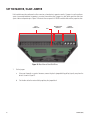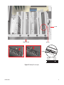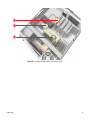
1
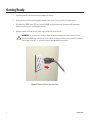
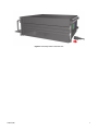
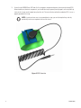
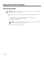
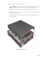
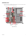
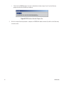
DX8000 Hard Drive
Upgrade Installation
For Single Drive Systems
DX8000 Digital Video Recorder
C1606M (6/04)
Protecting people and property in a million locations worldwide.
Introduction
The following instructions serve as a guide for replacing the primary hard disk drive of your DX8000 Series digital video
recorder (DVR). Step-by-step directions show you how to install the DX8000-UP250 hard disk upgrade kit.
PARTS LIST
NOTE: This upgrade kit includes a Pelco-certified hard disk drive. Using any other hard disk drive with the
DX8000 voids the manufacturer’s warranty for the DX8000.
Qty
1
2
1
Description
250 GB hard disk drive
Mounting screws
DX8000 Reinstallation CD
TOOLS NEEDED
1
1
4
C1606M (6/04)
Phillips-head screwdriver #1 (nonmagnetic)
Properly grounded ESD wrist strap and mat
Small containers for storing screws (optional)
1
Getting Ready
1.
Familiarize yourself with the instructions throughout this manual.
2.
Check that you have all the necessary parts and tools. Refer to the Parts List and Tools Needed sections.
3.
Shut down the DX8000 Series DVR unit. Refer to DX8000 Installation Manual or Operations and Programming
Manual for instructions on shutting down your unit.
4.
Unplug the power cord from the wall socket and then from the rear of the DVR.
WARNING: For safety reasons, you must remove the power cord because current continues to flow
through the DX8000 even when the unit is off. Remove the power cord from the wall socket first and then
from the rear of the DVR. It is critical that the unit be unplugged for your safety.
Figure 1. Removing Power Cord from Wall
2
C1606M (6/04)
Figure 2. Removing Power Cord from Unit
C1606M (6/04)
3
5.
Ensure that the DX8000 Series DVR and all of its components are protected against electrostatic discharge (ESD).
Before handling any electronic components, you should take steps to ground yourself properly so that any built-up
static electric charges are dissipated away from the unit. The most effective method for combating ESD is to use a
properly grounded wrist strap.
NOTE: If you do not have access to a grounded wrist strap, you can discharge built-up static by
periodically touching an unpainted section of the chassis.
Figure 3. ESD Protection
4
C1606M (6/04)
Prepare Unit for Drive Installation
OPEN THE UNIT CHASSIS
WARNING: The chassis assembly includes parts with sharp edges. To avoid injury, use caution when working in
and around the DX8000’s chassis and components.
1.
If the DX8000 is mounted in a rack, remove it and transport it to an area that will provide full access to the unit
chassis:
a.
b.
c.
Disconnect any cables or connections that might restrict access to or the removal of the unit.
Unscrew the fasteners that are securing the unit in the rack.
Carefully lift the unit out of the rack.
NOTE: Removing the DX8000 from a rack may require more than one person. Refer to the DX8000
Installation Manual for rack mounting information.
2.
C1606M (6/04)
Place the DX8000 on a flat surface with ample workspace.
5
3.
Using a Phillips-head screwdriver, remove the chassis cover:
WARNING: Make sure unit is turned off and you are wearing a properly grounded ESD wrist strap
before attempting to open the DX8000 chassis cover. Refer to the Getting Ready section.
a.
Remove the two top-most screws on the left and right side panels of the DX8000. Refer to Figure 4.
b.
Remove the four silver screws fastening the cover to the rear of the unit. These screws are the ones closest to
the top of the unit. Refer to Figure 4.
c.
Carefully remove the chassis cover by sliding it back and up. Set aside the cover. Figure 5 illustrates the
interior of the DX8000.
Figure 4. Removing Chassis Cover
6
C1606M (6/04)
COMPONENT LAYOUT
Figure 5 shows the location of your DX8000 Series DVR’s major components. Certain cables and components have been
omitted from the illustration in this manual for the purpose of clarity.
DIMM SOCKETS (RAM)
POWER SUPPLY
CD-RW
CPU
HARD DRIVE
REAR OF DVR
FRONT OF DVR
VGA CARD
PCI SLOT 1
2
3
4
5
6
REAR CROSS-BRACE
MOTHERBOARD
IDE CONNECTORS
(SECONDARY)
FRONT CROSS-BRACE
MOTHERBOARD
IDE CONNECTORS
(PRIMARY)
Figure 5. DX8000 Interior
C1606M (6/04)
7
Move the Front Cross-Brace
1.
Unscrew and lift out the front cross-brace (found at the center of the unit). Moving this part out of the way will
make it easier for you to access the hard drive mounting baskets.
a.
Use a Phillips-head screwdriver to remove the two flat-head screws that secure the front cross-brace. Refer to
Figure 6.
Figure 6. Removing Front Cross-Brace
8
C1606M (6/04)
b.
Carefully place the cross-brace and fan across the rear section of the unit. Refer to Figure 7.
WARNING: Do not disconnect the wires or remove the front cross-brace entirely from the unit—
doing so may cause damage to the fan’s power connection.
Figure 7. Placing Front Cross-Brace Across Rear of Unit
C1606M (6/04)
9
Disconnect the Data and Power Cables
When removing the data and power cables, pull the connectors straight out. Do not rock connectors back and forth or
remove a cable by pulling it by its wires or cable.
1.
Remove the IDE data cable from the existing hard drive, CD-RW drive, and motherboard:
a.
Carefully pull the plastic tab of each cable connector away from the hard drive and CD-RW drive. Refer to
Figure 8.
b.
Following the same procedure, remove the other end of the IDE cable from the drive interface connector on the
motherboard. Refer to Figure 8.
HARD DRIVE
IDE CONNECTOR
1a
CD-RW
IDE CONNECTOR
1a
MOTHERBOARD
IDE CONNECTOR
1b
Figure 8. Removing the IDE Data Cable
10
C1606M (6/04)
2.
Remove the power connectors from the hard drive.
HARD DRIVE
POWER CONNECTOR
Figure 9. Removing Hard Drive Power Connection
C1606M (6/04)
11
Remove the Drive Mount Basket
1.
Remove the first hard drive mounting basket:
a.
Using a Phillips-head screwdriver, unfasten and save the four screws that attach the drive basket to the
chassis. Refer to Figure 10.
b.
Gently lift the basket up and out with the drive attached. Be careful not to force the basket free or to disturb
other components inside the unit.
Figure 10. Removing Hard Drive Basket
12
C1606M (6/04)
Replace the Primary Hard Disk
NOTE: This upgrade kit includes a Pelco-certified hard disk drive. Using any other hard disk drive with the
DX8000 voids the manufacturer’s warranty for this product.
REMOVE THE ORIGINAL DRIVE
1.
2.
Using a Phillips-head screwdriver, unfasten the screws attaching the drive to the basket. Refer to Figure 11.
Gently remove the original hard drive from the basket and set aside.
Figure 11. Removing the Original Hard Drive
C1606M (6/04)
13
MOUNT THE NEW DRIVE
1.
Mount the new drive in the drive basket. Use the drive slot closest to the CD-RW drive. Refer to Figure 12.
a.
b.
c.
Make sure the drive is mounted in the basket so that access to the connectors is not blocked.
Attach the drive to the basket using the two screws that came with the upgrade kit.
Tighten the screws securely but do not over-tighten.
Figure 12. Inserting the New Drive into the Basket
14
C1606M (6/04)
2.
Mount the drive basket back into the chassis:
a.
Align the basket and press down firmly to ensure that it fits flush against the top of the chassis bracket. Refer
to Figure 13.
b.
Secure the drive basket to the chassis using the four screws you set aside earlier.
Figure 13. Replacing Drive Basket
C1606M (6/04)
15
SET THE MASTER / SLAVE JUMPER
Each hard drive must be configured as either a master or slave device to operate correctly. A jumper is used to configure
a pair of connected hard drives to operate in a master/slave relationship. A jumper is a small plastic part that slides over
a pair of drive configuration pins. Figure 14 illustrates the rear panel of a 250 GB hard disk drive and the jumper location.
DATA
CONNECTOR
PIN 1
MASTER/SLAVE
JUMPERS
POWER
CONNECTOR
Figure 14. Rear View of Hard Disk Drive
1.
16
Set the jumper:
a.
Using your fingernails or a pair of tweezers, remove the plastic jumper block by pulling it gently away from the
drive as shown in Figure 15.
b.
Set the drive to be the master disk by replacing the jumper block.
C1606M (6/04)
CD-RW
FRONT OF DVR
MASTER
JUMPER
MASTER
SETTING
SLAVE
SETTING
Figure 15. Setting Drive Jumper
C1606M (6/04)
17
RECONNECT THE DATA AND POWER CABLES
IMPORTANT: Data and power cable connectors fit together only one way. All connectors are keyed to
ensure that they are inserted in the proper orientation. Examine the drive, motherboard, and cable
connectors before installation so that connectors are properly aligned. Make sure connectors are seated
in the mating connectors securely, but do not force the connection. When installing drive power cables,
push the connectors straight in or out; do not rock connectors back and forth.
1.
18
Connect the CD-RW drive to the system motherboard using the data cable that you removed earlier:
a.
Connect the gray connector of the data cable that came with your DX8000 to the CD-RW drive as illustrated in
Figure 16.
b.
Connect the black connector of the data cable to the newly installed hard drive. Refer to Figure 16.
c.
Connect the blue connector of the data cable to the primary (blue) IDE connector on the system motherboard.
Refer to Figure 16.
C1606M (6/04)
1b
1a
1c
Figure 16. Installing CD-RW and Hard Drive Data Cable
C1606M (6/04)
19
3.
Connect the hard drive power connector according to the diagram in Figure 17.
HARD DRIVE
POWER CONNECTOR
Figure 17. Installing Power Connector
20
C1606M (6/04)
Reassemble the Unit
1.
Replace the front cross-brace and secure it with the flat-head screws you set aside earlier. Refer to Figure 18.
Figure 18. Replacing Front Cross-Brace
C1606M (6/04)
21
2.
Replace the chassis cover using the same screws you removed from the side and rear of the unit. Refer to Figure 19.
Figure 19. Replacing Chassis Cover
22
C1606M (6/04)
3.
Reinstall the unit in a rack enclosure if necessary, and reconnect all cables and peripheral equipment that you
removed earlier.
4.
Plug the power cord back into the power supply and then into the wall.
5.
Turn on the power switch and allow the unit to start up and find the new hard disk. This may take several minutes.
6.
Proceed to the following sections for instructions on how to initialize the drive for service in the DX8000.
ON/OFF
Figure 20. Restarting Unit
C1606M (6/04)
23
Install Software on the New Drive
To complete the installation of a new primary hard disk in your DX8000, all necessary operating system and application
software must be installed. Installation of this software will require that you configure the DX8000 to boot from the
CD/DVD drive. Then follow the on-screen directions to prepare the new hard disk drive for service in your DVR.
CONFIGURE SYSTEM TO BOOT FROM CD/DVD
To change the boot drive from the hard disk to the CD/DVD drive:
24
1.
Insert the DX8000 Reinstallation CD into your DVR’s CD/DVD drive.
2.
Boot the DX8000 Series DVR by turning on the power switch, or restart the system if it is already running. Refer to
the Operations and Programming Manual for instructions on restarting the DX8000.
C1606M (6/04)
3.
Press the Delete key on the keyboard as the system is booting and before the Windows® operating system loads.
The BIOS main screen appears.
AwardBIOS Setup Utility
Advanced
Power Boot Exit
Main
Item Specific Help
System
System
Legacy
Floppy
Time
Date
Diskette A
3 Mode Support
[19:48:32]
[02/04/2004]
[1.44M, 2.5 in.]
[Disabled]
Primary Master
Primary Slave
Secondary Master
Secondary Slave
Keyboard Features
[Maxtor 7Y250P0]
[TEAC
CD-W552E]
[AUTO]
[AUTO]
Language
Supervisor Password
User Password
Halt On
Installed Memory
[English (US)]
[Disabled]
[Disabled]
[All but keyboard]
256MB
F1 Help
ESC Exit
Select Item -/+
Change
Select Menu Enter Select
Supervisor password
controls full access.
<Enter> to change
password. <Enter> again
to disable password.
Values
F5 Setup Defaults
Sub-Menu F10 Save and Exit
Figure 21. DX8000 BIOS Setup Main Screen
C1606M (6/04)
25
4.
If you receive a prompt requesting that you enter a password, contact your system administrator for assistance
logging into and changing the DX8000 BIOS Setup.
5.
Use the cursor control (arrow) keys on your keyboard and move right to the Boot option in the Main screen.
6.
Press the minus (-) key on your keyboard to change the boot sequence from the hard disk to the CD or DVD drive
installed on your system. The screen should look something like the example in Figure 22.
6
Main
AwardBIOS Setup Utility
Advanced
Power Boot Exit
Item Specific Help
1.
2.
3.
4.
APAPI CD-ROM
IDE Hard Drive
Other Boot Device
Removable Device
[TEAC CD-W552E]
[Maxtor 7Y250P0]
[INT18 Device (Networ] Boot Sequence:
[Disabled]
<Enter> To select
the device.
Plug & Play O/S
Reset Configuration data
Boot Virus Detection
Quick Power On Self Test
Boot Up Floppy Seek
Full Screen Logo
Interrupt Mode
F1 Help
ESC Exit
[No]
[No]
[Disabled]
[Enabled]
[Disabled]
[Enabled]
[APIC]
Select Item -/+
Change
Select Menu Enter Select
To select the boot
sequence, use the up or
down arrow. Press <+>
to move the device up
the list, or <-> to
move it down the list.
Values
F5 Setup Defaults
Sub-Menu F10 Save and Exit
Figure 22. BIOS Boot Screen with CD/DVD Drive at Top
26
C1606M (6/04)
7.
Press the F10 function key on your keyboard to save and exit the BIOS setup screen.
8.
Finalize BIOS changes:
•
•
9.
C1606M (6/04)
To accept the boot sequence changes and reboot, press the Enter key.
To cancel the changes, press the Esc key and then press Ctrl+Alt+Delete keys simultaneously to reboot.
Wait while your system boots from the DX8000 Reinstallation CD and then proceed to the following section.
27
INSTALL SOFTWARE
1.
The DX8000 Recovery dialog box appears.
2
3
Figure 23. DX8000 Recovery Dialog Box
28
2.
Carefully read the warning presented in the dialog box and type the word Yes to confirm that you want to continue
the reinstallation process.
3.
Click the Proceed button to continue the installation procedure. The Partition Size Verification dialog box appears.
C1606M (6/04)
4
Figure 24. Partition Size Verification Dialog Box
4.
Click Yes. The Proceed with Disk Restore dialog box appears.
CAUTION: Proceeding with the recovery procedure will permanently overwrite the software and data
stored on your system’s C: drive.
C1606M (6/04)
29
5
Figure 25. Proceed with Disk Restore Dialog Box
5.
Click Yes. A progress bar appears reporting the progress of the system installation. When the recovery process is
complete, you will be prompted to restart your computer.
CAUTION: At this time, the DX8000 Reinstallation procedure will replace the contents of your primary C:
drive partition with a hard disk image of the DX8000 system and application software. The imaging
process may take up to 20 minutes. Do not press any keys or restart your DVR during the installation
procedure.
6
Figure 26. Clone Complete Dialog Box
6.
30
Click Reset Computer. The DVR restarts.
C1606M (6/04)
7.
Press the Delete key on the keyboard as the system is booting and before the Windows operating system loads. The
BIOS main screen appears.
AwardBIOS Setup Utility
Advanced
Power Boot Exit
Main
Item Specific Help
System
System
Legacy
Floppy
Time
Date
Diskette A
3 Mode Support
[19:48:32]
[02/04/2004]
[1.44M, 2.5 in.]
[Disabled]
Primary Master
Primary Slave
Secondary Master
Secondary Slave
Keyboard Features
[Maxtor 7Y250P0]
[TEAC
CD-W552E]
[AUTO]
[AUTO]
Language
Supervisor Password
User Password
Halt On
Installed Memory
[English (US)]
[Disabled]
[Disabled]
[All but keyboard]
256MB
F1 Help
ESC Exit
Select Item -/+
Change
Select Menu Enter Select
Supervisor password
controls full access.
<Enter> to change
password. <Enter> again
to disable password.
Values
F5 Setup Defaults
Sub-Menu F10 Save and Exit
Figure 27. DX8000 BIOS Setup Main Screen
8.
If you receive a prompt requesting that you enter a password, contact your system administrator for assistance
logging into and changing the DX8000 BIOS Setup.
9.
Use the cursor control (arrow) keys on your keyboard and move right to the Boot option in the Main screen.
C1606M (6/04)
31
10. Press the minus (-) key on your keyboard to change the boot sequence from the CD/DVD drive back to the hard disk.
The screen should look something like the example in Figure 28.
10
Main
AwardBIOS Setup Utility
Advanced
Power Boot Exit
Item Specific Help
1.
2.
3.
4.
IDE Hard Drive
APAPI CD-ROM
Other Boot Device
Removable Device
[Maxtor 7Y250P0]
[TEAC CD-W552E]
[INT18 Device (Networ] Boot Sequence:
[Disabled]
<Enter> To select
the device.
Plug & Play O/S
Reset Configuration data
Boot Virus Detection
Quick Power On Self Test
Boot Up Floppy Seek
Full Screen Logo
Interrupt Mode
F1 Help
ESC Exit
[No]
[No]
[Disabled]
[Enabled]
[Disabled]
[Enabled]
[APIC]
Select Item -/+
Change
Select Menu Enter Select
To select the boot
sequence, use the up or
down arrow. Press <+>
to move the device up
the list, or <-> to
move it down the list.
Values
F5 Setup Defaults
Sub-Menu F10 Save and Exit
Figure 28. BIOS Boot Screen with Hard Disk Drive at Top
11. Press the F10 function key on your keyboard to save and exit the BIOS setup screen.
12. Press the Enter key to accept the change and reboot your DVR.
32
C1606M (6/04)
Initialize the New Drive
1.
While the DX8000 starts, the built-in setup program will automatically detect the newly installed drive and
reconfigure the basic settings of the unit to make use of the increased storage capacity. No action by the user is
necessary during this step.
2.
After the unit has detected and prepared the newly added drive, the Windows® operating system will automatically
reboot to complete the drive preparation process. No action by the user is necessary during this step.
3.
After the system has been rebooted, the PDB Initialize screen appears. Before the new drive can be used to store
video data, it must be made compatible with the DX8000’s Pelco proprietary database (PDB) file structure. Follow
the steps below after the PDB Initialize screen appears to finalize storage setup:
a.
Click the plus (+) sign next to the blue box—the one that reads, “Space on one or more hard disk drives has
not yet been allocated to the PDB database.” Refer to Figure 29.
3a
Figure 29. Opening List of Drives
C1606M (6/04)
33
b.
Click the Not Used button. Refer to Figure 30. A drop-down menu appears.
3b
Figure 30. Opening Drive Option Menu
c.
Select the Allocation option from the drop-down menu.
3c
Figure 31. Selecting Allocation Option
34
C1606M (6/04)
d.
Click Begin Allocation.
3d
Figure 32. Initializing Drive Allocation
e.
The Formatting dialog box appears. Click Start.
3e
Figure 33. Formatting Dialog Box
C1606M (6/04)
35
f.
Wait while the DX8000 prepares the newly installed drive for video storage. You will see the following
progress bar while the formatting is underway.
Figure 34. PDB Database Creation Progress Bar
4.
36
After the storage allocation procedure is complete, the DX8000 will reboot automatically and the unit will be ready
to resume service.
C1606M (6/04)
PRODUCT WARRANTY AND RETURN INFORMATION
WARRANTY
Pelco will repair or replace, without charge, any merchandise proved defective in material or workmanship for a period of one year after the date of
shipment.
Exceptions to this warranty are as noted below:
•
•
•
•
•
•
•
•
•
Five years on the following fixed camera models: CC3701H-2, CC3701H-2X, CC3751H-2, CC3651H-2X, MC3651H-2, and MC3651H-2X.
Three years on all other fixed camera models (including Camclosure® Integrated Camera Systems) and Genex® Series (multiplexers, server, and keyboard).
Two years on all standard motorized or fixed focal length lenses.
Two years on Legacy®, CM6700/CM6800/CM8500/CM9500/CM9700 Series Matrix, DF5 and DF8 Series Fixed Dome products.
Two years on Spectra®, Esprit®, and PS20 Scanners, including when used in continuous motion applications.
Two years on Esprit® and WW5700 series window wiper (excluding wiper blades).
Eighteen months on DX Series digital video recorders and NVR300 network video recorders.
One year (except video heads) on video cassette recorders (VCRs). Video heads will be covered for a period of six months.
Six months on all pan and tilts, scanners or preset lenses used in continuous motion applications (that is, preset scan, tour and auto scan modes).
Pelco will warrant all replacement parts and repairs for 90 days from the date of Pelco shipment. All goods requiring warranty repair shall be sent freight
prepaid to Pelco, Clovis, California. Repairs made necessary by reason of misuse, alteration, normal wear, or accident are not covered under this warranty.
Pelco assumes no risk and shall be subject to no liability for damages or loss resulting from the specific use or application made of the Products. Pelco’s
liability for any claim, whether based on breach of contract, negligence, infringement of any rights of any party or product liability, relating to the Products
shall not exceed the price paid by the Dealer to Pelco for such Products. In no event will Pelco be liable for any special, incidental or consequential damages
(including loss of use, loss of profit and claims of third parties) however caused, whether by the negligence of Pelco or otherwise.
The above warranty provides the Dealer with specific legal rights. The Dealer may also have additional rights, which are subject to variation from state to
state.
If a warranty repair is required, the Dealer must contact Pelco at (800) 289-9100 or (559) 292-1981 to obtain a Repair Authorization number (RA), and provide
the following information:
1. Model and serial number
2. Date of shipment, P.O. number, Sales Order number, or Pelco invoice number
3. Details of the defect or problem
If there is a dispute regarding the warranty of a product which does not fall under the warranty conditions stated above, please include a written explanation
with the product when returned.
Method of return shipment shall be the same or equal to the method by which the item was received by Pelco.
RETURNS
In order to expedite parts returned to the factory for repair or credit, please call the factory at (800) 289-9100 or (559) 292-1981 to obtain an authorization
number (CA number if returned for credit, and RA number if returned for repair).
All merchandise returned for credit may be subject to a 20% restocking and refurbishing charge.
Goods returned for repair or credit should be clearly identified with the assigned CA or RA number and freight should be prepaid. Ship to the appropriate
address below.
If you are located within the continental U.S., Alaska, Hawaii or Puerto Rico, send goods to:
Service Department
Pelco
3500 Pelco Way
Clovis, CA 93612-5699
If you are located outside the continental U.S., Alaska, Hawaii or Puerto Rico and are instructed to return goods to the USA, you may do one of the following:
If the goods are to be sent by a COURIER SERVICE, send the goods to:
Pelco
3500 Pelco Way
Clovis, CA 93612-5699 USA
If the goods are to be sent by a FREIGHT FORWARDER, send the goods to:
Pelco c/o Expeditors
473 Eccles Avenue
South San Francisco, CA 94080 USA
Phone: 650-737-1700
Fax: 650-737-0933
® Pelco, the Pelco logo, Spectra, Genex, Legacy, Coaxitron, Esprit and Camclosure are registered trademarks of Pelco.
™ Spectra II and Spectra III are trademarks of Pelco.
© Copyright 2004, Pelco. All rights reserved.
Worldwide Headquarters
3500 Pelco Way
Clovis, California 93612 USA
USA & Canada
Tel: 800/289-9100
Fax: 800/289-9150
International
Tel: 1-559/292-1981
Fax: 1-559/348-1120
www.pelco.com
ISO9001
United States | Canada | United Kingdom | The Netherlands | Singapore | Spain | Scandinavia | France | Middle East
Pelco and the Pelco logo are registered trademarks of Pelco.
Windows is a registered trademark of Microsoft Corporation.
C1606M (6/04)
© Copyright 2004, Pelco. All rights reserved.