1
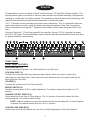
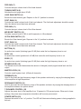
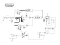
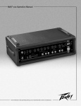
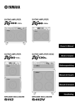
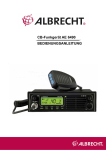
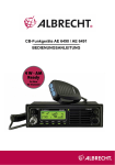
Intended to alert the user to the presence of uninsulated “dangerous voltage” within the product’s
enclosure that may be of sufficient magnitude to constitute a risk of electric shock to persons.
Intended to alert the user of the presence of important operating and maintenance (servicing)
instructions in the literature accompanying the product.
CAUTION: Risk of electrical shock — DO NOT OPEN!
CAUTION: To reduce the risk of electric shock, do not remove cover. No user serviceable parts inside. Refer
servicing to qualified service personnel.
WARNING: To prevent electrical shock or fire hazard, do not expose this appliance to rain or moisture. Before
using this appliance, read the operating guide for further warnings.
Este símbolo tiene el propósito, de alertar al usuario de la presencia de “(voltaje) peligroso” que no tiene
aislamiento dentro de la caja del producto que puede tener una magnitud suficiente como para constituir
riesgo de corrientazo.
Este símbolo tiene el propósito de alertar al usario de la presencia de instruccones importantes sobre la
operación y mantenimiento en la literatura que viene con el producto.
PRECAUCION: Riesgo de corrientazo — ¡No abra!
PRECAUCION: Para disminuír el riesgo de corrientazo, no abra la cubierta. No hay piezas adentro que el usario
pueda reparar. Deje todo mantenimiento a los técnicos calificados.
ADVERTENCIA: Para evitar corrientazos o peligro de incendio, no deje expuesto a la lluvia o humedad este
aparato Antes de usar este aparato, Iea más advertencias en la guía de operación.
Ce symbole est utilisé pur indiquer à l’utilisateur la présence à l’intérieur de ce produit de tension nonisolée dangereuse pouvant être d’intensité suffisante pour constituer un risque de choc électrique.
Ce symbole est utilisé pour indiquer à l’utilisateur qu’il ou qu’elle trouvera d’importantes instructions sur
l’utilisation et l’entretien (service) de l’appareil dans la littérature accompagnant le produit.
ATTENTION: Risques de choc électrique — NE PAS OUVRIR!
ATTENTION: Afin de réduire le risque de choc électrique, ne pas enlever le couvercle. Il ne se trouve à l’intérieur
aucune pièce pouvant être reparée par l’utilisateur. Confier I’entretien à un personnel qualifié.
AVERTISSEMENT: Afin de prévenir les risques de décharge électrique ou de feu, n’exposez pas cet appareil à la
pluie ou à l’humidité. Avant d’utiliser cet appareil, lisez les avertissements supplémentaires situés dans le guide.
Dieses Symbol soll den Anwender vor unisolierten gefährlichen Spannungen innerhalb des Gehäuses
warnen, die von Ausreichender Stärke sind, um einen elektrischen Schlag verursachen zu können.
Dieses Symbol soll den Benutzer auf wichtige Instruktionen in der Bedienungsanleitung aufmerksam
machen, die Handhabung und Wartung des Produkts betreffen.
VORSICHT: Risiko — Elektrischer Schlag! Nicht öffnen!
VORSICHT: Um das Risiko eines elektrischen Schlages zu vermeiden, nicht die Abdeckung enfernen. Es befinden
sich keine Teile darin, die vom Anwender repariert werden könnten. Reparaturen nur von qualifiziertem
Fachpersonal durchführen lassen.
ACHTUNG: Um einen elektrischen Schlag oder Feuergefahr zu vermeiden, sollte dieses Gerät nicht dem Regen
oder Feuchtigkeit ausgesetzt werden. Vor Inbetriebnahme unbedingt die Bedienungsanleitung lesen.
2
ENGLISH
Congratulations on your purchase of the all new Revolution® 112 TransTube® Series amplifier. This
amp represents years of research on vacuum tube emulation and channel switching configurations,
resulting in a totally new TransTube package. The preamp has been designed using technology that
redefines tube-like distortion and harmonic generation in solid-state amps.
The T™ Dynamics circuitry simulates tube power amp compression. This, in combination with resonance and presence circuitry, yields the closest tube amp simulation to date. This compression
effect is increased by turning the T™ Dynamics control down, which lowers the power level of the
amp.
Using the Revolution® 112 with an external 8 ohm speaker, like our 112 SX, increases the power
from 80 to 100 watts. The footswitchable channel selection and the footswitchable effects loop allow
for greater flexibility in performance.
1
2
3
4
5
6
7
8
10
11
9
12
14
15
16
17
18
19
20
22
23
21
13
FRONT PANEL
FRONT PANEL FEATURES
HIGH GAIN INPUT (1)
Used for most electric guitars. It is 6 dB louder than Low Gain input.
LOW GAIN INPUT (2)
Provided for instruments that have extremely high outputs, which can result in overdriving
(distorting) the High Gain input. If both inputs are used simultaneously, the output levels are the
same (both are Low Gain).
VOLUME (3)
Controls the volume level of the Clean channel.
BRIGHT SWITCH (4)
Provides a preset boost (6 dB) to treble frequencies. To activate, depress the switch to its “in”
position.
CHANNEL SELECT SWITCH (5)
Allows selection of the Ultra or Clean channel. The “in” position of the switch selects the Ultra
channel and the “out” position selects Clean.
NOTE: Channel selection may also be achieved by the remote footswitch. If remote selection
is desired, the channel switch must be in the “in” position.
LOW, MID, AND HIGH EQ (6)
Passive tone controls that regulate the low, mid, and high frequencies of the Clean channel.
3
PRE GAIN (7)
Controls the input volume level of the Lead channel.
THRASH SWITCH (8)
Notches the mid range about 20 dB.
LEAD GAIN SWITCH (9)
Boosts the Lead channel gain. Depress to the “in” position to activate.
POST GAIN (10)
Controls the overall volume level of the Lead channel. The final level adjustment should be made
after the desired sound has been achieved.
PRE GAIN (11)
Controls the input volume level of the Ultra channel.
MID BOOST SWITCH (12)
Provides a preset boost (3 dB) to mid frequencies in Ultra channel.
ULTRA GAIN SWITCH (13)
Boosts the Ultra channel gain. Depress to the “in” position to activate.
POST GAIN (14)
Controls the overall volume level of the Ultra channel. The final level adjustment should be made
after the desired sound has been achieved.
BOTTOM (15)
An active tone control (shelving type ±15 dB) that varies the low frequency boost or cut.
BODY (16)
An active tone control (peak/notch ±15 dB) that varies the mid frequency boost or cut.
EDGE (17)
An active tone control (shelving type ±15 dB) that varies the high frequency boost or cut.
REVERB LEVEL (18)
The Reverb level control determines the amount of delayed (reverb) signal mixed back into the
output.
MASTER LEVEL (19)
Controls overall system level. (Affects all channels)
PRESENCE (20)
Used to fine-tune the high frequency range of the speaker enclosure by varying the damping factor
of the amplifier at high frequencies.
RESONANCE SWITCH (21)
Used to fine-tune the low frequency range of the speaker enclosure by varying the damping factor of
the amplifier between two preset values.
T-DYNAMICS CONTROL (22)
Adjusts the power level of the amplifier from 10 percent to 100 percent power. When set to lower
settings, the power amp compression simulation will be more pronounced.
POWER SWITCH (23)
Depress the switch to the “on” position. The LED will illuminate indicating power is being supplied to
the unit.
4
BACK PANEL
24
25
26
27
28
29
30 31
32
BACK PANEL FEATURES
GROUND SWITCH (24)
Three position rocker-type switch, which, in most applications, should be operated in its center or
zero position. There may be some situations when audible hum and/or noise will come from the
loudspeaker. If this situation arises, position the ground switch to either positive or negative (+ or -)
until the noise is minimized.
Note: Should the noise problem continue, consult your Authorized Peavey Dealer, the Peavey
Factory, or a qualified service technician. THE GROUND SWITCH IS NOT FUNCTIONAL ON
220/240 VOLT MODELS.
AC LINE CORD—120 V PRODUCTS ONLY (25)
For your safety, we have incorporated a three-wire line (mains) cable with proper grounding
facilities. It is not advisable to remove the ground pin under any circumstances. If it is
necessary to use the equipment without proper grounding facilities, suitable grounding adaptors
should be used. Less noise and greatly reduced shock hazard exists when the unit is operated with
the proper grounded receptacles.
(For UK Only) As the colours of the wires in the mains lead of this apparatus may not correspond
with the coloured markings identifying the terminals in your plug, proceed as follows:
• The wire which is coloured green and yellow must be connected to the terminal which is marked
by the letter E or by the earth symbol, or coloured green or green and yellow.
• The wire which is coloured blue must be connected to the terminal which is marked with the letter
N or coloured black.
• The wire which is coloured brown must be connected the terminal which is marked with the letter
L or the coloured red.
EXTERNAL SPEAKER JACK (26)
Provided for connection of external speaker cabinet. Minimum external speaker impedance is
8 ohms. Use of an external 8 ohm speaker boosts amp output to 100 watts.
REMOTE FOOTSWITCH JACK (27)
Provided for the connection of the supplied remote footswitch. The footswitch is used to select the
Ultra, Lead, or Clean channel and bypass the EFX Loop. When using remote footswitch, always
insert the plug fully (second click) to ensure proper operation. The proper footswitch is Peavey part
number 90000019.
POWER AMP INPUT (28)
Used to connect Line Level signal to the power amplifier.
5
PREAMP OUT (29)
The preamp out can be used to route the amplified signal to a mixing console, tape recorder, etc.
Connect the preamp output using a shielded cable to an input of the tape recorder, mixer, etc. This
patch does not affect the operation of the amplifier.
EFFECTS LEVEL SWITCH (30)
Selects the effects loop operating level: -10 dBV (0.3V RMS) when “out” and 0 dBV (1V RMS) when
“in.”
EFFECTS RETURN (31)
Input for returning signals from external low-level effects or signal processing equipment.
EFFECTS SEND (32)
Output for supplying signals to external low-level effects or signal processing equipment.
6
REVOLUTION® 112 SPECIFICATIONS
Power Amplifier Section:
Effects Send:
The following specs are measured at 1 kHz with the master EQ
set flat at 0 dB, all gain switches in the out position, the main
reverb at 0, nominal signal levels are with channel level controls
set at 5, minimum level are with channel level controls set at 10.
Load Impedance: 1 K Ohms or greater
Nominal Output Level:
Efx. Level switch “out”: -10dBV, 0.3V RMS
Efx. Level switch “in”: 0dBV, 1V RMS
Rated Power and Load:
Effects Return:
Power specs measured with T™ Dynamics @ 10
80 W RMS into 8 ohms
100 W RMS into 4 ohms
Impedance: High-Z, 22 K ohms
Designed Input Level:
Efx. Level switch “out”: -10dBV, 0.3V RMS
Power @ Clipping: (typically)
Efx. Level switch “in”: 0dBV, 1V RMS
(5% THD, 1 kHz, 120 V AC line)
80 W RMS into 8 ohms
100 W RMS into 4 ohms
(Switching jack provides Effects Send to Effects Return connection when not used)
Frequency Response:
Preamp Output:
+0/-3 dB 65 Hz to 20 kHz @ 65 W RMS into 8 ohms
Load Impedance: 1 K ohm or greater
Nominal Output Level: 0 dBV, 1 V RMS
Hum and Noise:
Greater than 80 dB below rated power
Power Amp Input:
Power Consumption:
Impedance: High-Z, 25K Ohms
Designed Input Level: 0 dBV, 1 V RMS
(Switching jack provides preamp output to power amp input connection when not used)
300 W @ 60 Hz, 120 V AC, Domestic
300 W @ 50/60 Hz, 220-230/240 V AC, Export
PREAMP SECTION
The following specs are measured @ 1 kHz with the controls
preset as follows:
Push Bright, Off (Out)
Channel Select Clean (Out)
Low & High @ 10
Mid @ 0
Lead Pre & Post Gain @ 10
Lead Gain & Mid Boost, Off (Out)
Ultra Pre & Post @ 10
Ultra Gain & Mid Boost, Off (Out)
Bottom, Body & Edge @ 0
Reverb @ 0
Master Level @ 10
Normal Levels are with Clean Volume @ 5
Minimum Levels are with Clean Volume @ 10
System Hum and Noise @ Nominal Input Level:
(20 Hz to 20 kHz unweighted)
Greater than 70 dB below rated power
Equalization:
Special Low, Mid, and High passive type EQ
(Clean channel only)
Push Bright: +6 dB @ 2 kHz (Clean channel only)
Special Bottom, Body, and Edge active EQ (Lead and
Ultra channels)
Push Thrash: -12 dB @ 1 kHz (Lead channel)
Push Mid Boost: +3dB @ 1kHz (Ultra channel only)
Push Gain: Increases gain (Lead and Ultra channels)
Presence: +6dB @ 5kHz
Push Resonance: +6 dB @ resonant frequency of cabinet
Preamp High Gain Input:
External Footswitch Functions
(part number 90000019):
Impedance: High-Z, 1 M ohm
Nominal Input Level: -15 dBV, 175 mV RMS
Minimum Input Level: -25dBV, 55 mV RMS
Maximum Input Level: 0 dBV, 1 V RMS
Ultra/Lead: Selects Ultra or Lead channel
Bypass/Clean: Lead and Ultra channel defeat
(with front panel Channel switch “in”)
Select Effects: Effects loop bypass
Preamp Low Gain Input:
Impedance: High-Z, 44 K ohms
Nominal Input Level: -9 dBV, 350 mV RMS
Minimum Input Level: -19 dBV, 110 mV RMS
Maximum Input Level: 6 dBV, 2 V RMS
Dimensions and Weight:
20.0” H x 23.5” W x 11.375” D
(50.8 cm x 59.7 cm x 28.9 cm)
45.9 lbs. (20.8 kg)
7
REVOLUTION® 112
BLOCK
DIAGRAM
REVOLUTION
BLOCK
DIAGRAM
(FLOWCHART)
(FLOWCHART)
TONE
CLEAN
LO
MID
HI
VOLUME
CLEAN
PUSH
BRIGHT
PUSH
THRASH
1st
GAIN STAGE
HIGH
GAIN AMP
FOOT
SWITCH
EFX.
EQUALIZATION
POST
BYPASS
INPUTS
SWITCH LOGIC
CLEAN/ULTRA
SWITCH
LOGIC
LEAD
LEAD
LEAD/
ULTRA
PUSH
CHANNEL
FOOT
SWITCH
BOT.
BODY
EDGE
PRE GAIN
LEAD
PUSH
GAIN
EFX.
RETURN
EFX
LEVEL
EFX.
SEND
8
FOOT
SWITCH
POST
ULTRA
PREGAIN
ULTRA
ULTRA
PUSH
MID
BOOST
PUSH
GAIN
REVERB
LEVEL
RESONANCE
PRESENCE
PREAMP
OUT
MASTER
LEVEL
SPEAKER
POWER
AMP
T.DYNAMICS
EXTERNAL
SPEAKER
POWER
AMP IN
REVOLUTION® 112
RECOMMENDED
TONE SETTINGS
Recommended Tone Settings for:
Basic Clean, Thrash Metal, Moderate Distortion
In
Basic Clean
In
In
In
Out
Thrash
Metal
Moderate
Distortion
In
EQ
Volume, Reverb & Master = Adjust to preference
Recommended Tone Settings for:
Loud & Clean, Mild Distortion & Classic Heavy Lead
Out
Loud & Clean
Out
In
Out
Mild
Distortion
Out
Classic
Heavy
In
EQ
Reverb & Master = Adjust to preference
Tone Settings given are general and will vary according to the type of guitar, gauge, type of strings, the type of pickup and
even the type of pick. Personal preference, playing style and type of music greatly contribute to desired tonality.
9
ESPAÑOL
Lo felicitamos por adquirir el amplificador completamente novedoso Revolution® 112 de la serie
TransTube®. Este amplificador representa años de investigación en la emulación de tubos de vacío
y las configuraciones de conmutación de canales, que dieron como resultado un sistema TransTube
totalmente renovado. Este preamplificador fue diseñado utilizando una tecnología que redefine los
conceptos de distorsión de tubos y generación de frecuencias armónicas de los amplificadores de
estado sólido.
Los circuitos T™ Dynamics simulan la compresión de los amplificadores de potencia con tubos de
vacío. Todo esto, junto con los circuitos de resonancia y presencia, produce la
simulación que más se asemeja hasta la fecha a los amplificadores con tubos de vacío. Este efecto
de compresión aumenta cuando se reduce el control T™ Dynamics, que a su vez baja el nivel de
potencia del amplificador.
Si el amplificador Revolution® 112 se utiliza junto con un altavoz externo de 8 Ω, como nuestro
112 SX, la potencia aumenta de 80 a 100 W. La selección de canales y el circuito de efectos, que
pueden conmutarse mediante pedales, ofrecen aún más flexibilidad de operación.
Consulte los diagramas del panel delantero en la sección de inglés de est manual.
PANEL FRONTAL
FUNCIONES DEL PANEL FRONTAL
ENTRADA DE ALTA GANANCIA (1)
Utilizada para la mayoría de las guitarras eléctricas. Su salida tiene 6 dB más de nivel que la
entrada de baja ganancia.
ENTRADA DE BAJA GANANCIA (2)
Provista para los instrumentos de salidas extremadamente altas, que pueden dar como resultado la
sobreexcitación (distorsión) de la entrada de alta ganancia. Si ambas entradas se utilizan
simultáneamente, los niveles de salida son los mismos (ambos son de baja ganancia).
VOLUMEN (3)
Controla el nivel de volumen total del canal limpio.
CONMUTADOR DE BRILLO (4)
Provee un refuerzo preconfigurado (6 dB) para frecuencias altas. Para activarlo, lleve el conmutador hacia adentro.
CONMUTADOR DE SELECCIÓN DE CANAL (5)
Permite la selección de los canales ultra o limpio. Cuando está hacia adentro, selecciona el canal
ultra; hacia afuera, el canal limpio.
NOTA: La selección de canales también puede efectuarse con el conmutador de pedal
remoto. Si se desea utilizar el conmutador de pedal, el selector de canales debe estar
hacia adentro.
ECUALIZACIÓN DE FRECUENCIAS BAJAS, MEDIAS Y ALTAS (6)
Controles de tono pasivos que regulan las frecuencias altas, medias y bajas del canal limpio.
10
PREGANANCIA (7)
Controla el nivel del volumen de entrada del canal líder.
CONMUTADOR DE SONIDO THRASH (8)
Aumenta las frecuencias medias en alrededor de 20 dB.
CONMUTADOR DE GANANCIA DEL CANAL LÍDER (9)
Refuerza la ganancia del canal líder. Para activarlo, llévelo hacia adentro.
POSGANANCIA (10)
Controla el nivel general del volumen del canal líder. El ajuste del nivel final debe efectuarse
después de haber logrado el sonido deseado.
PREGANANCIA (11)
Controla el nivel del volumen de entrada del canal ultra.
CONMUTADOR DE REFUERZO DE FRECUENCIAS MEDIAS (12)
Proporciona un refuerzo preconfigurado (3 dB) a las frecuencias intermedias del canal ultra.
CONMUTADOR DE GANANCIA DEL CANAL ULTRA (13)
Refuerza la ganancia del canal ultra. Para activarlo, llévelo hacia adentro.
POSGANANCIA (14)
Controla el nivel general del volumen del canal ultra. El ajuste del nivel final debe efectuarse
después de haber logrado el sonido deseado.
FRECUENCIAS INFERIORES (15)
Control de tono activo (recorte de ± 15 dB) que varía el refuerzo o el corte de las frecuencias bajas.
FRECUENCIAS CENTRALES (16)
Control de tono activo (picos/valles de ± 15 dB) que varía el refuerzo o el corte de las frecuencias
medias.
FRECUENCIAS SUPERIORES (17)
Control de tono activo (recorte de ± 15 dB) que varía el refuerzo o el corte de las frecuencias altas.
NIVEL DE REVERBERACIÓN (18)
El control del nivel de reverberación determina la intensidad de las señales demoradas
(reverberación) que se combinan nuevamente en la salida.
NIVEL MAESTRO (19)
Controla el nivel de volumen general del sistema. (Afecta todos los canales.)
PRESENCIA (20)
Utilizado para graduar con precisión la gama de frecuencias altas del gabinete del altavoz, variando
el factor de atenuación del amplificador para los agudos.
CONMUTADOR DE RESONANCIA (21)
Utilizado para graduar con precisión los márgenes de frecuencias bajas del gabinete del altavoz,
variando el factor de atenuación del amplificador entre tres valores preconfigurados.
CONTROL TDYNAMICS (22)
Regula el nivel de potencia del amplificador entre 10 y 100%. Cuando se configura en los valores
inferiores, la simulación de la compresión del amplificador de potencia será más pronunciada.
11
INTERRUPTOR DE ALIMENTACIÓN (23)
Para encender la unidad, lleve este interruptor a la posición de encendido. El indicador LED se
ilumina para indicar que la unidad recibe alimentación.
POSTERIOR PANEL
25
24
26
27
28
29 30
31
FUNCIONES DEL PANEL POSTERIOR
CABLE DE ALIMENTACIÓN DE CA – Sólo en modelos para 120 V (24)
Para su seguridad, hemos incorporado un cable de alimentación de línea (alimentación
principal) de tres conductores con un terminal de toma de tierra apropiado. No se recomienda
eliminar el terminal de toma de tierra en ninguna circunstancia. Si es necesario utilizar el equipo
sin los elementos de toma de tierra apropiados, deben utilizarse adaptadores de toma de tierra
adecuados. Cuando la unidad se opera con tomacorrientes con tomas de tierra apropiadas, hay
menos ruidos y un riesgo mucho menor de choques eléctricos.
ENCHUFE HEMBRA PARA ALTAVOZ EXTERNO (25)
Provisto para la conexión de un gabinete de altavoz externo. La impedancia mínima del
altavoz externo es de 8 Ω. La utilización de un altavoz externo de 8 Ω refuerza la salida
del amplificador hasta 100 W.
ENCHUFE HEMBRA PARA EL CONMUTADOR DE PEDAL REMOTO (26)
Provisto para conectar el conmutador de pedal remoto que se suministra. El conmutador de pedal
se utiliza para seleccionar los canales ultra, líder o limpio y para evitar el circuito de efectos
especiales (EFX). Cuando se utiliza el conmutador de pedal remoto, se debe siempre enchufar el
conector completamente (dos clics) para asegurar el funcionamiento correcto. El conmutador de
pedal ad5 accesorio Peavey Nº 90000019.
ENTRADA DE AMPLIFICADOR DE POTENCIA (27)
Se utiliza para conectar la señal de nivel de línea al amplificador de potencia.
SALIDA DE PREAMPLIFICADOR (28)
La salida del preamplificador puede utilizarse para llevar la señal amplificada a consolas
mezcladoras, grabadores de cinta, etc. Conecte la salida del preamplificador a una entrada
del grabador de cinta, mezclador, etc., mediante un cable blindado. Esta conexión no afecta
el funcionamiento del amplificador.
CONMUTADOR DE NIVEL DE EFECTOS (29)
Selecciona el nivel operativo del circuito de efectos: –10 dB V (0,3 Vef) cuando está hacia afuera
y 0 dB V (1 Vef) cuando está hacia adentro.
RETORNO DE EFECTOS (30)
Entrada para devolver señales de un equipo externo de efectos o de procesamiento de señales de
bajo nivel.
SEÑAL DE MUESTRA DE EFECTOS (31)
Salida para proveer señales a equipos externos de efectos o de procesamiento de señales de bajo
nivel.
12
FRANÇAIS
Nous vous félicitons pour l’achat de cet amplificateur TransTube® Revolution® 112. La technologie
TransTube® représente des années de recherche sur l’émulation du ”son lampe” et sur les amplis
pour guitare en général. Le préampli a été développé afin de recréer toutes les caractéristiques du
rendu harmonique et de la distortion de lampes.
Le circuit T™ Dynamics simule parfaitement la compression d’étages de puissance à lampes. Ceci,
en plus des contrôles de présence et résonance permet au Révolution de fournir l’émulation la plus
réussie des tubes électroniques réalisée jusqu’à présent. Cet effet de compression décroît lorsque
vous tournez le contrôle T™ Dynamics dans le sens horaire et s’accroît dans le sens inverse.
En utilisant le Revolution® 112 avec un haut-parleur externe de 8 Ohm tel le 112 SX, la puissance de
l’amplificateur passe de 80 à 100 Watt. La sélection des canaux et de la boucle d’effets par
footswitch vous assure une flexibilité maximum.
Veuillez-vous référer au <<front panel>> art situé dans
la section en langue anglaise de ce manual.
FACE AVANT
FEATURES FACE AVANT
ENTRÉE HIGH GAIN (1)
Utilisez cette entrée pour la plupart des guitares électriques. Elle est 6 dB plus forte que l’entrée
Low Gain.
ENTRÉE LOW GAIN (2)
Utilisez cette entrée avec des instruments possédant un trés haut niveau de sortie et pouvant
provoquer une distortion (non musicale) à l’entrée High Gain. Si les deux entrées sont utilisées
simultanément, les niveaux d’entrée seront les mêmes (de type Low Gain).
VOLUME (3)
Contrôle le volume général du canal Clean.
SÉLECTEUR BRIGHT (4)
Boost les fréquences aiguës de 6 dB. Enfoncez le sélecteur pour activer.
SÉLECTEUR DE CANAL (5)
Permet la sélection des canaux Ultra ou Clean. En position enfoncée, le canal Ultra est sélectionné
et en position ressortie, le canal Clean est actif.
NOTE: La sélection des canaux peut aussi être réalisée par footswitch. Pour son utilisation,
enfoncez le sélecteur.
EQ LOW, MID ET HIGH (6)
Contrôles de tonalité passifs affectant les graves médiums et aiguês du canal Clean.
PRE GAIN (7)
Contrôle le niveau d’entrée du canal Lead.
SÉLECTEUR THRASH (8)
Creuse les médiums d’environ 20 dB.
13
SÉLECTEUR LEAD GAIN (9)
Boost le gain du canal Lead. Enfoncez le sélecteur pour activer.
POST GAIN (10)
Contrôle le volume général du canal Lead. Ce contrôle doit être ajusté une fois que vous avez
trouvé votre son.
PRE GAIN (11)
Contrôle le niveau d’entrée du canal Ultra.
SÉLECTEUR MID BOOST (12)
Boost les fréquences médiums de 3 dB pour le canal Ultra.
SÉLECTEUR ULTRA GAIN (13)
Boost le gain du canal Ultra. Enfoncez le sélecteur pour activer.
POST GAIN (14)
Contrôle le volume général du canal Ultra. Ce contrôle doit être ajusté une fois que vous avez
trouvé votre son.
BOTTOM (15)
Contrôles de tonalité actif (±15 dB) affectant le niveau des fréquences graves.
BODY (16)
Contrôles de tonalité actif (±15 dB) affectant le niveau des fréquences médiums.
EDGE (17)
Contrôles de tonalité actif (±15 dB) affectant le niveau des fréquences aiguës.
NIVEAU RÉVERBE (18)
Le contrôle de niveau de réverbe détermine la quantité de signal affecté par l’effet ajoutée au signal
original.
NIVEAU MASTER (19)
Contrôle le volume général de l’amplificateur (tous les canaux sont affectés)
PRESENCE (20)
Permet d’ajuster la reproduction des hautes fréquences de l’enceinte en faisant varier le facteur
d’amortissement des hautes fréquences (ajoute de la brillance au signal).
SÉLECTEUR DE RESONANCE (21)
Permet d’ajuster la reproduction des basses fréquences de l’enceinte en faisant varier le facteur
d’amortissement des basses fréquences (contrôle le punch de l’amplificateur).
CONTRÔLE T-DYNAMICS (22)
Ajuste la puissance de l’amplificateur de 10 à 100 % de la puissance maximale. Pour des réglages
modérés, la simulation de la compression de l’étage de puissance sera plus prononcée.
INTERRUPTEUR D’ALIMENTATION (23)
Appuyez sur cet interrupteur pour mettre l’appareil sous tension. La led d’alimentation s’allumera
pour indiquer que l’appareil est alimenté.
14
FACE ARRIÈRE
24
25
26
27
28
29 30
31
FEATURES FACE ARRIÈRE
PRISE D’ALIMENTATION (24)
Le Revolution 112 dispose d'une prise d'alimentation IEC permettant de connecter un cordon
d’alimentation standard aux normes IEC. L'appareil doit toujours être relié à la terre. Votre
sécurité en dépend.
SORTIE HP EXTERNE (25)
Permet de connecter un haut-parleur externe à l’amplificateur. L’impédance minimale de ce HP
doit être de 8 Ohm. L’utilisation d’une enceinte externe de 8 Ohm fait passer la puissance de
l’ampli de 80 à 100 Watt.
PRISE FOOTSWITCH (26)
Permet la connexion du footswitch inclu. Il permet la sélection des canaux Ultra, Lead ou Clean
et la commutation de la boucle d’effets. Insérez correctement la prise du pédalier (2 clics) pour un
fonctionnement idéal. La référence Peavey du footswitch est: 90000019.
ENTRÉE POWER AMP IN (27)
Permet de connecter à l’amplificateur de puissance des signaux au niveau Ligne .
SORTIE PREAMP OUT (28)
Cette sortie permet d’acheminer le signal sortant du préampli vers une console de mixage, une
platine cassette, etc... Utilisez un câble blindé pour ce type de connexions. L’utilisation de cette
sortie n’affecte pas le fonctionnement de l’amplificateur.
SÉLECTEUR DE NIVEAU DE LA BOUCLE D’EFFETS (29)
Détermine le niveau de fonctionnement de la boucle d’effets: -10 dBV (0.3V RMS) en position sortie
ou 0 dBV (1V RMS) en position enfoncée.
EFFECTS RETURN (30)
Permet le retour du signal traité par un processeur d’effets externe ou par une pédale d’effet placée
dans la boucle d’effets.
EFFECTS SEND (31)
Sortie de la boucle d’effets permettant d’alimenter des processeurs ou pédales d’effets externes.
15
DEUTSCH
Herzlichen Glückwunsch zum Erwerb Ihres brandneuen Revolution® 112 der TransTube®
Verstärkerserie. Dieser Verstärker repräsentiert jahrelange Forschung auf dem Gebiet der
Vakuumröhrenemulation und Channel Switching Konfigurationen, resultierend in einem völlig neuen
Trans Tube Packet. Dieser Preamp wurde mit einer Technologie ausgestattet, die die röhrenähnliche
Verzerrung und harmonische Generierung in Verstärkern neu definiert.
Der T™ Dynamics Schaltkreis simuliert die Kompression eines Röhrenverstärkers. Dies, in
Kombination mit der Resonance und Presence Schaltkreistechnologie ist bis zum heutigen Tag die
wohl erfolgreichste und vielversprechenste Röhrenverstärker Emulationsannäherung. Erreicht wird
dieser Kompressionseffekt durch runterdrehen des T™ Dynamics Reglers, infolge dessen sich der
Leistungspegel des Amps senkt.
Der Einsatz des Revolution® 112 mit einem externen 8 Ohm Lautsprecher, wie unseren 112 SX,
erhöht die Leistung von 80 auf 100 Watt. Die Kanalwahl per Fußschalter und die via Fußschalter
steuerbare Effektloop sorgen für größere Performance Flexibilität.
Siehe Diagramm der Frontplatte im englischen Teil des Handbuchs.
FRONT PANEL
FRONT PANEL FEATURES
HIGH GAIN INPUT (1)
Dieser Eingang wird für die meisten E-Gitarren benutzt. Er ist 6 dB lauter als der Low Gain Input.
LOW GAIN INPUT (2)
Vorgesehen für Instrumente mit extrem hohen Ausgangssignalen, die zu einer Übersteuerung
(Verzerrung) des High Gain Input führen. Bei gleichzeitig benutzten Eingängen sind die
Ausgangspegel dieselben (beide Low Gain).
VOLUME/LAUTSTÄRKE (3)
Regelt den Lautstärkepegel des Clean Channel.
BRIGHT SCHALTER (4)
Bietet einen Preset Boost (6 dB) um Frequenzen zu verdreifachen. Zur Schalteraktivierung diesen
reindrücken.
CHANNEL WAHLSCHALTER (5)
Selektieren Sie hiermit entweder den Ultra oder Clean Channel. Gedrückt wählen Sie den Ultra
Channel ansonsten den Clean Channel.
ANMERKUNG: Die Kanalwahl läßt sich auch per Fußschalter realisieren. Dazu muß der
Channel Wahlschalter gedrückt sein („In“-Position).
LOW, MID, AND HIGH EQ (6)
Passive Klangregler, mit denen sich die Nieder-, Mittel-, und Hochfrequenzen des Clean Channels
einstellen lassen.
16
PRE GAIN (7)
Kontrolliert den Input Lautstärkepegel des Lead Channel.
THRASH SCHALTER (8)
Regelt den Mittenbereich um 20 dB.
LEAD GAIN SCHALTER (9)
Verstärkt den Lead Channel Gain. Zur Aktivierung drücken.
POST GAIN (10)
Kontrolliert den Hauptlautstärkepegel des Lead Channel. Die finale Pegeljustierung sollte
vorgenommen werden, nachdem der gewünschte Sound gefunden ist.
PRE GAIN (11)
Kontrolliert den Input Lautstärkepegel des Ultra Channel.
MID BOOST SCHALTER (12)
Bietet eine voreingestellte Verstärkung (3 dB) der mittleren Frequenzen im Ultra Channel.
ULTRA GAIN SCHALTER (13)
Verstärkt den Ultra Channel Gain. Zur Aktivierung drücken.
POST GAIN (14)
Kontrolliert den Hauptlautstärkepegel des Ultra Channel. Die finale Pegeljustierung sollte
vorgenommen werden, nachdem der gewünschte Sound gefunden ist.
BOTTOM (15)
Ein aktiver Klangregler (Typ Shelving ±15 dB), der die Verstärkung/Abschwächung der
Niederfrequenzen variiert.
BODY (16)
Ein aktiver Klangregler (Peak/Notch ±15 dB), der die Verstärkung/Abschwächung der mittleren
Frequenzen variiert.
EDGE (17)
Ein aktiver Klangregler (Typ Shelving ±15 dB), der die Verstärkung/Abschwächung der
Hochfrequenzen variiert.
REVERB LEVEL (18)
Der Reverb Pegelregler legt die Größe des verzögerten (Reverb) Signals fest, das dem Output
wieder beigemischt wird.
MASTER LEVEL (19)
Kontrolliert und regelt den Systempegel. (Beeinflußt alle Kanäle).
PRESENCE REGLER (20)
Der hohe Frequenzbereich der Lautsprecherbox wird feinabgestimmt, indem der Dämpfungsfaktor
des Verstärkers für hohe Frequenzen variiert wird.
17
RESONANCE REGLER (21)
Der tiefe Frequenzbereich der Lautsprecherbox wird feinabgestimmt, indem der Dämpfungsfaktor
des Verstärkers für tiefe Frequenzen variiert wird.
T-DYNAMICS CONTROL (22)
Justiert den Leistungspegel des Verstärkers von 10 Prozent bis 100 Prozent Leistung. Bei niedrigen
Einstellungen kommt die Kompressionssimulation des Verstärkers mehr zum Ausdruck.
NETZSCHALTER (23)
Bringen Sie den Schalter in die „ON“ Position. Die LED leuchtet auf und zeigt damit an, daß das
Gerät eingeschaltet ist.
RÜCKSEITIGE
25
24
26
27
28
29 30
31
RÜCKSEITIGE FEATURES
AC ANSCHLUßKABEL— NUR 120 V PRODUKTE (24)
Für Ihre Sicherheit liegt ein 3-adriges Netzkabel mit entsprechender Erdungsvorrichtung bei.
Unter keinen Umständen den Erdungsstift entfernen. Sollte es vorkommen das Equipment
ohne angemessene Erdungsvorrichtung einzusetzen, dann sollten Sie auf entsprechende Adapter
zurückgreifen. Mit angemessener Schutz- bzw. Erdungseinrichtung mindern Sie nicht nur
Rauschen, sondern vermeiden auch zum größten Teil eine Schlaggefahr.
EXTERNE LAUTSPRECHERBUCHSE (25)
Dient dem Anschluß eines externen Lautsprechergehäuses. Die minimale externe
Lautsprecherimpedanz beträgt 8 Ohm. Der Einsatz eines externen 8 Ohm Lautsprechers
hebt den Amp Out auf 100 Watt an.
REMOTE FUßSCHALTERBUCHSE (26)
Dient dem Anschluß des mitgelieferten Fußschalters (Peavey Teilenr.: #9000019). Der Fußschalter
wird zum Selektieren des Ultra, Lead, oder Clean Channels benutzt und zur Umgehung der EFX
Loop benutzt. Achten Sie beim Fußschaltereinsatz darauf, daß der Stecker immer vollständig
eingesteckt ist, (zweites Klickgeräusch), um eine ordnungsgemäße Bedienung zu gewährleisten.
POWER AMP INPUT (27)
Dient dem Leistungsverstärker zur Aufnahme eines Line Level Signals.
PREAMP OUT (28)
Dieser Ausgang läßt sich zum Routen eines verstärkten Signals an eine Mischpultkonsole, eines
Tape Recorders, etc. benutzen. Verbinden Sie den Preamp Output über ein abgeschirmtes Kabel
mit dem Eingang eines Tape Recorders, Mixers, etc. Diese Verbindung beeinflußt die sonstige
Funktion des Verstärkers nicht.
18
EFFECTS LEVEL SCHALTER (29)
Selektiert den Arbeitspegel der Effektloop: -10 dBV (0.3V RMS) wenn bei nicht gedrücktem Schalter
und 0 dBV (1V RMS) wenn der Schalter gedrückt ist („In“-Posotion).
EFFECTS RETURN (30)
Eingang für die Signalrückführung externer Low-Level Effekte oder Equipment für die
Signalverarbeitung.
EFFECTS SEND (31)
Ausgang für die Signalbereitstellung externer Low-Level Effekte oder Equipment für die
Signalverarbeitung.
19
NOTES:
20
NOTES:
21
PEAVEY ELECTRONICS CORPORATION LIMITED WARRANTY
Effective Date: July 1, 1998
What This Warranty Covers
Your Peavey Warranty covers defects in material and workmanship in Peavey products purchased and serviced in the U.S.A. and Canada.
What This Warranty Does Not Cover
The Warranty does not cover: (1) damage caused by accident, misuse, abuse, improper installation or operation, rental, product modification or
neglect; (2) damage occurring during shipment; (3) damage caused by repair or service performed by persons not authorized by Peavey; (4) products
on which the serial number has been altered, defaced or removed; (5) products not purchased from an Authorized Peavey Dealer.
Who This Warranty Protects
This Warranty protects only the original retail purchaser of the product.
How Long This Warranty Lasts
The Warranty begins on the date of purchase by the original retail purchaser. The duration of the Warranty is as follows:
Product Category
Duration
Guitars/Basses, Amplifiers, Pre-Amplifiers, Mixers, Electronic
Crossovers and Equalizers
2 years *(+ 3 years)
Drums
2 years *(+ 1 year)
Enclosures
3 years *(+ 2 years)
Digital Effect Devices and Keyboard and MIDI Controllers
1 year *(+ 1 year)
Microphones
2 years
Speaker Components (incl. speakers, baskets, drivers,
diaphragm replacement kits and passive crossovers)
and all Accessories
1 year
Tubes and Meters
90 days
[*denotes additional warranty period applicable if optional Warranty Registration Card is completed and returned to Peavey by original retail purchaser within 90
days of purchase.]
What Peavey Will Do
We will repair or replace (at Peavey's discretion) products covered by warranty at no charge for labor or materials. If the product or component must
be shipped to Peavey for warranty service, the consumer must pay initial shipping charges. If the repairs are covered by warranty, Peavey will pay the
return shipping charges.
How To Get Warranty Service
(1) Take the defective item and your sales receipt or other proof of date of purchase to your Authorized Peavey Dealer or Authorized Peavey
Service Center.
OR
(2) Ship the defective item, prepaid, to Peavey Electronics Corporation, International Service Center, 412 Highway 11 & 80 East, Meridian, MS 39301
or Peavey Canada Ltd., 95 Shields Court, Markham, Ontario, Canada L3R 9T5. Include a detailed description of the problem, together with a copy of
your sales receipt or other proof of date of purchase as evidence of warranty coverage. Also provide a complete return address.
Limitation of Implied Warranties
ANY IMPLIED WARRANTIES, INCLUDING WARRANTIES OF MERCHANTABILITY AND FITNESS FOR A PARTICULAR PURPOSE, ARE LIMITED
IN DURATION TO THE LENGTH OF THIS WARRANTY.
Some states do not allow limitations on how long an implied warranty lasts, so the above limitation may not apply to you.
Exclusions of Damages
PEAVEY'S LIABILITY FOR ANY DEFECTIVE PRODUCT IS LIMITED TO THE REPAIR OR REPLACEMENT OF THE PRODUCT, AT PEAVEY'S
OPTION. IF WE ELECT TO REPLACE THE PRODUCT, THE REPLACEMENT MAY BE A RECONDITIONED UNIT. PEAVEY SHALL NOT BE
LIABLE FOR DAMAGES BASED ON INCONVENIENCE, LOSS OF USE, LOST PROFITS, LOST SAVINGS, DAMAGE TO ANY OTHER EQUIPMENT
OR OTHER ITEMS AT THE SITE OF USE, OR ANY OTHER DAMAGES WHETHER INCIDENTAL, CONSEQUENTIAL OR OTHERWISE, EVEN IF
PEAVEY HAS BEEN ADVISED OF THE POSSIBILITY OF SUCH DAMAGES
Some states do not allow the exclusion or limitation of incidental or consequential damages, so the above limitation or exclusion may not
apply to you.
This Warranty gives you specific legal rights, and you may also have other rights which vary from state to state.
If you have any questions about this warranty or service received or if you need assistance in locating an Authorized Service Center, please contact
the Peavey International Service Center at (601) 483-5365 / Peavey Canada Ltd. at (905) 475-2578.
Features and specifications subject to change without notice.
sm
The Sound of Experience
22
IMPORTANT SAFETY INSTRUCTIONS
WARNING: When using electric products, basic cautions should always be followed, including the following:
1. Read all safety and operating instructions before using this product.
2.
All safety and operating instructions should be retained for future reference.
3.
Obey all cautions in the operating instructions and on the back of the unit.
4.
All operating instructions should be followed.
5.
This product should not be used near water (i.e., a bathtub, sink, swimming pool, wet basement, etc).
6.
This product should be located so that its position does not interfere with its proper ventilation. It should not be placed flat against a wall
or placed in a built-in enclosure that will impede the flow of cooling air.
7.
This product should not be placed near a source of heat such as a stove, radiator, or another heat producing amplifier.
8.
Connect only to a power supply of the type marked on the unit adjacent to the power supply cord.
9.
Never break off the ground pin on the power supply cord. For more information on grounding, write
for our free booklet “Shock Hazard and Grounding."
10. Power supply cords should always be handled carefully. Never walk or place equipment on power supply cords. Periodically check cords for
cuts or signs of stress, especially at the plug and the point where the cord exits the unit.
11 The power supply cord should be unplugged when the unit is to be unused for long periods of time.
12. If this product is to be mounted in an equipment rack, rear support should be provided.
13. Metal parts can be cleaned with a damp rag. The vinyl covering used on some units can be cleaned with a damp rag or an ammonia-based
household cleaner if necessary. Disconnect unit from power supply before cleaning.
14. Care should be taken so that objects do not fall and liquids are not spilled into the unit through the ventilation holes or any other openings.
15. This unit should be checked by a qualified service technician if:
a. The power supply cord or plug has been damaged.
b. Anything has fallen or been spilled into the unit.
c. The unit does not operate correctly.
d. The unit has been dropped or the enclosure damaged.
16. The user should not attempt to service this equipment. All service work should be done by a qualified service technician.
17. This product should be used only with a cart or stand that is recommended by Peavey Electronics.
18. Exposure to extremely high noise levels may cause a permanent hearing loss. Individuals vary considerably in susceptibility to noise induced
hearing loss, but nearly everyone will lose some hearing if exposed to sufficiently intense noise for a sufficient time. The U.S. Government’s
Occupational Safety and Health Administration (OSHA) has specified the following permissible noise level exposures:
Duration Per Day In Hours
8
6
4
3
2
1 1/2
1
1/2
1/4 or less
Sound Level dBA, Slow Response
90
92
95
97
100
102
105
110
115
According to OSHA, any exposure in excess of the above permissible limits could result in some hearing loss. Ear plugs or protectors to the ear
canals or over the ears must be worn when operating this amplification system in order to prevent a permanent hearing loss if exposure is in excess
of the limits as set forth above. To ensure against potentially dangerous exposure to high sound pressure levels, it is recommended that all persons
exposed to equipment capable of producing high sound pressure levels such as this amplification system be protected by hearing protectors while
this unit is in operation.
SAVE THESE INSTRUCTIONS!
23
Features and specifications subject to change without notice.
Peavey Electronics Corporation • 711 A Street • Meridian • MS • 39301
(601) 483-5365 • FAX (601) 486-1278 • www.peavey.com
©1998
80304470
Printed in the U.S.A. 9/98