1
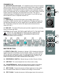
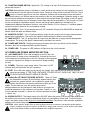
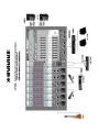
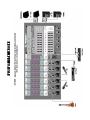
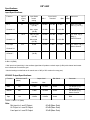
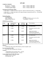
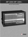
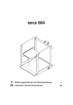
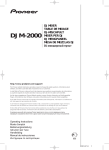
®
OWNER’S MANUAL
Intended to alert the user to the presence of uninsulated “dangerous voltage” within the product’s
enclosure that may be of sufficient magnitude to constitute a risk of electric shock to persons.
Intended to alert the user of the presence of important operating and maintenance (servicing)
instructions in the literature accompanying the product.
CAUTION: Risk of electrical shock — DO NOT OPEN!
CAUTION: To reduce the risk of electric shock, do not remove cover. No user serviceable parts inside. Refer
servicing to qualified service personnel.
WARNING: To prevent electrical shock or fire hazard, do not expose this appliance to rain or moisture. Before
using this appliance, read the operating guide for further warnings.
Este símbolo tiene el propósito, de alertar al usuario de la presencia de “(voltaje) peligroso” que no tiene
aislamiento dentro de la caja del producto que puede tener una magnitud suficiente como para constituir
riesgo de corrientazo.
Este símbolo tiene el propósito de alertar al usario de la presencia de instruccones importantes sobre la
operación y mantenimiento en la literatura que viene con el producto.
PRECAUCION: Riesgo de corrientazo — ¡No abra!
PRECAUCION: Para disminuír el riesgo de corrientazo, no abra la cubierta. No hay piezas adentro que el usario
pueda reparar. Deje todo mantenimiento a los técnicos calificados.
ADVERTENCIA: Para evitar corrientazos o peligro de incendio, no deje expuesto a la lluvia o humedad este
aparato. Antes de usar este aparato, Iea más advertencias en la guía de operación.
Ce symbole est utilisé pur indiquer à l’utilisateur la présence à l’intérieur de ce produit de tension nonisolée dangereuse pouvant être d’intensité suffisante pour constituer un risque de choc électrique.
Ce symbole est utilisé pour indiquer à l’utilisateur qu’il ou qu’elle trouvera d’importantes instructions sur
l’utilisation et l’entretien (service) de l’appareil dans la littérature accompagnant le produit.
ATTENTION: Risques de choc électrique — NE PAS OUVRIR!
ATTENTION: Afin de réduire le risque de choc électrique, ne pas enlever le couvercle. Il ne se trouve à l’intérieur
aucune pièce pouvant être reparée par l’utilisateur. Confier I’entretien à un personnel qualifié.
AVERTISSEMENT: Afin de prévenir les risques de décharge électrique ou de feu, n’exposez pas cet appareil à la
pluie ou à l’humidité. Avant d’utiliser cet appareil, lisez les avertissements supplémentaires situés dans le guide.
Dieses Symbol soll den Anwender vor unisolierten gefährlichen Spannungen innerhalb des Gehäuses
warnen, die von Ausreichender Stärke sind, um einen elektrischen Schlag verursachen zu können.
Dieses Symbol soll den Benutzer auf wichtige Instruktionen in der Bedienungsanleitung aufmerksam
machen, die Handhabung und Wartung des Produkts betreffen.
VORSICHT: Risiko — Elektrischer Schlag! Nicht öffnen!
VORSICHT: Um das Risiko eines elektrischen Schlages zu vermeiden, nicht die Abdeckung enfernen. Es befinden
sich keine Teile darin, die vom Anwender repariert werden könnten. Reparaturen nur von qualifiziertem
Fachpersonal durchführen lassen.
ACHTUNG: Um einen elektrischen Schlag oder Feuergefahr zu vermeiden, sollte dieses Gerät nicht dem Regen
oder Feuchtigkeit ausgesetzt werden. Vor Inbetriebnahme unbedingt die Bedienungsanleitung lesen.
ENGLISH
XR™ 600F Powered Sound Reinforcement Mixing Console
General Description:
Congratulations on your purchase of the XR™ 600F powered mixer. Within one compact unit, we
have packed feature after feature, each displaying the latest technology available. Here are several
features you will certainly want to notice:
• Six low-noise, low-Z mic preamps
• Four true high-Z 1/4" mic inputs
• Three-band equalization (Channels 1-6)
• Monitor send (each channel)
• EFX send (Channels 1-6)
• -25 dB pad (Channels 1-4)
• 16-bit, DSP-based stereo reverb/delay with two parameter controls
• Two nine-band graphic EQs with FLS® Feedback Locating System ®
• 48 V phantom power
• Main/Monitor mode switch
• 2x200 W @ 4 ohms internal power amplifier
• 420 W @ 8 ohms in bridge mode
• DDT™ speaker protection
The standard channels (1-4) feature discrete low noise mic preamps with globally switched phantom
power, true high-impedance 1/4" mic inputs, low-cut filters, and three-band EQs. Two additional
channels (5-6) offer balanced XLR mic inputs and dual 1/4" line level inputs. Finally, channel 7 offers
dual RCA jacks for summing stereo outputs (from tape, CD, etc.) into mono.
The master section features a unique graphic equalizer/power amp mode switch. Without patching,
the XR 600F can be used as a mixer/amplifier for the mains (default). This mode utilizes both EQ’s
and both channels of the amplifier to supply a left and right speaker (mains). In the Main/Monitor
mode, one graphic and amplifier can be used for monitor and the other graphic and amplifier for the
main signal.
Also included in the master section are two digital effects (reverb and delay) from the award winning
Deltafex™ digital signal processor. By including separate Size/Time and Color/Feedback controls, the
user can create many effect settings from the two we provided. All channels, except channel 7, have
a dedicated digital effects send routed directly to the DSP effects processor.
To take advantage of the XR 600F’s powerful features, please read this owner’s manual carefully
and keep it as a reference. This manual includes several sections detailing individual areas of mixer
operation, including: control functions, set-up, and applications in sound reinforcement.
CHANNEL SECTION:
CHANNELS 1-4
1. MIC INPUT: XLR balanced, low-impedance channel input optimized for a
microphone or other low-level source. Pin 2 is the positive input. Because of the
wide range of gain adjustment, signal levels as high as +10 dBV (2.45 V RMS)
can be accommodated. When the phantom power is enabled, this connector
has +48 V on pins 2 and 3 with pin 1 as the ground reference. (The Mic Input
can also be found on channels 5 and 6.)
2. HI-Z/LINE INPUT: 1/4" balanced TRS high-impedance input. The tip is the
positive input, which can also be used for unbalanced inputs. A Pad (#3) switch
is provided to attenuate strong signals present at this input. Within the same
channel, the mic input and the Hi-Z/Line input cannot be used simultaneously.
3. PAD: Attenuates the input signal by 25 dB. If you find that barely touching
the Level control (#4) gives you an enormous increase in volume or if distortion
occurs, try using the Pad switch. In addition to increasing the dynamic range,
the channel input can now accommodate a higher input level before clipping.
This may be necessary with a close mic on loud guitar amplifiers or drum kits.
4. LEVEL: Sets the signal level sent to the Main bus. (The level control can
also be found on channels 5 through 7.)
5. MON: Adjusts the level of the channel signal (pre-EQ) that is added to the
Monitor mix. (The Monitor control can also be found on channels 5 through 7.)
This control is independent of the main channel level control (#4).
9
8
7
6
5
4
6. LOW EQ: A shelving type of active tone control that varies the bass
frequency levels ±15 dB at 70 Hz. It will add depth to thin signals, or clean up
muddy ones. (The low control can also be found on channels 5 through 7.)
7. MID EQ: Mid ±15 dB. This control sets the amount of cut and boost at the
mid-frequency (850 Hz). (The mid control can also be found on channels
5 through 6.)
3
8. HIGH EQ: A shelving type of active tone control that varies the treble
frequency levels ±15 dB at 12 kHz. It is designed to remove noise or to add
brilliance to the signal, depending on the quality of the source. (The high control
can also be found on channels 5 through 7.)
2
9. EFX: This control varies the level into the digital effects processor bus
adjusting the signal level from the particular channel to the digital processor.
(The effects control can also be found on channels 5 and 6.) The channel level
control (#4) also affects this level.
1
NOTE: Channels 5-7 contain features that differ from the previous channels.
Only those features are mentioned below. For information on features not
mentioned please refer to the section for Channels 1-4.
CHANNELS 5-6
10. LINE INPUTS (Dual Summed): 1/4" unbalanced inputs for line level signals.
Ideal for stereo outputs from midi sound modules and/or stereo audio equipment,
this input sums (mixes) two inputs (L/R) into one. However, it is not limited to
stereo combining. It is possible to insert the outputs of two keyboards into these
jacks, thus mixing them into one combined signal. In this case, balance of the two
signals would be controlled by the keyboard’s level control. This signal is
connected through a 25 dB pad to the mic input below it. Use of the mic input
allows channels 5 and 6 to duplicate channels 1-4.
10
CHANNEL 7
11. TAPE/LINE IN: This stereo RCA phono jack accepts a stereo input
(nominally -10 dBV) from the output of a tape deck or CD player and sums the
Left and Right channels into a mono signal found in the Main Mix and Monitor
Mix. These jacks can also be used as line inputs such as those found on
channels 5 and 6.
12. TAPE OUT: This stereo RCA phono jack provides a signal for the recording
inputs of a stereo tape deck.
CAUTION: DO NOT HOOK THE TAPE IN AND TAPE OUT TO THE INPUT AND
OUTPUT OF THE SAME DECK. DOING SO WILL FORM A LOOP
CAUSING SEVERE FEEDBACK. USE SEPERATE DECKS FOR
RECORDING AND PLAYBACK.
13
14
15
16
17
11
18
12
MASTER SECTION:
13. EFFECTS PEAK LED: Illuminates to indicate -6 dB of headroom before the
signals being sent to the effects circuit are clipped. Ideally, you would want this
LED to light only occassionally if at all. An occassional blink indicates that you
have the levels at an optimum setting. It is advisable to listen carefully to the
output at the same time in order to determine the final setting.
14. REVERB/DELAY SWITCH: Selects the type of effect; Reverb or Delay.
15. SIZE/TIME: This control adjusts the time of the reverb or delay.
16. COLOR/FEEDBACK: Adjusts the high-frequency content of the effects
signal. (While using the delay this control adjusts the feedback or depth.)
17. EFX TO MON: Controls the amount of effects signal sent to the monitor
mix. This control allows effects to be heard from the stage via the monitor.
18. EFX TO MAIN: Controls the amount of effects signal sent to the main mix.
29
19
20
22
21
23
24
25
26
27
28
19. FLS ® (Feedback Locating System ®): These LEDs illuminate to indicate the frequency band of highest
energy. When feedback occurs, this system will automatically indicate the graphics slider to use to decrease
that frequency band’s gain in order to lessen or eliminate feedback. (NOTE: These LEDs illuminate with any
audio signal, not just during feedback.)
20. GRAPHIC EQUALIZERS: These nine-band equalizers are fixed on one-octave centers. They are
designed for 12 dB of cut and 12 dB boost. They are connected directly to their power amplifier inputs.
21. SYSTEM MODE: This switch is used to configure the XR 600F as a dual mono amplifier for two main
outputs or one main and one monitor output. It is recessed to prevent accidental switching during a performance. Use a non-metallic object to change the switch position (e.g., a toothpick). The XR 600F is shipped
from the factory in the default setting of Main/Main (both amplifiers carry the same signal from the main bus).
When this switch is depressed the lower EQ / PWR AMP 2 remains connected to the main bus (mono). The
upper EQ / PWR AMP 1 then carries the monitor signal only, creating an entire PA and monitor mixing system
in one small, easy-to-carry package. And this change is accomplished without a single patch cord!
22. MONITOR LEVEL: Sets the overall level of the monitor signal that is sent to the Monitor Output Jack.
This control also sets the monitor level going to the power amp when in Main/Monitor mode (see System
Mode #21).
23. MAIN LEVEL: This is the master level control for the main mix and main output jack. This control sets
the Main level going to the power amp when in Main/Monitor mode and also in the Main/Main mode (see
System Mode #21). A good starting position for this control is the center detent position (12:00).
24. PHANTOM POWER SWITCH: Applies 48 V DC voltage to all input XLR connectors to power microphones that require it.
CAUTION! When phantom power is switched on, make sure that any channel you are plugging a mic into is
turned down in both the main and monitor mixes. Otherwise, there will be a loud pop in the PA. This is
normal. It is best to plug all mics into their respective channels with the phantom power switched off.
This reduces noise in the PA and reduces the chances of the mic being damaged. If phantom power is used,
do not connect unbalanced microphones or other devices that cannot handle this voltage to the XLR inputs.
(Some wireless receivers may be damaged; consult their manuals for compatibility.) The line input 1/4" jacks
are not connected to the phantom supply, and are safe for all inputs (balanced or unbalanced). An
unbalanced-to-balanced impedance converter, such as the Peavey 5116 or a Peavey 1:1 Interface Adapter,
can also be used to isolate a mic from phantom voltage.
25. EFX DEFEAT: This 1/4" jack accepts an on/off 1/4" footswitch (Peavey Part #00051000) to defeat the
effects of both the Main and Monitor mixes.
26. MONITOR OUTPUT: This 1/4" jack provides an output from the monitor mix to supply external power
amp/monitor combinations. The level of this signal is determined by the Monitor Level control.
27. MAIN OUTPUT: This 1/4" jack provides an output from the Main mix to supply external amp/speaker
combinations. The level of this signal is determined by the Main Level control.
28. POWER AMP INPUTS: Plugging into these jacks allows the user to go directly into the Graphic
Equalizer, then into its respective power amplifier channel.
29. POWER LED: The power on LED indicator will light when the unit is powered.
AC POWER AND POWER AMPLIFIER SECTION:
30. A/C POWER INLET: This is the receptacle for an IEC line cord,
which provides AC power to the mixer/amplifier. Connect the line cord
to this connector to provide power to the unit. Damage to the equipment
may result if improper line voltage is used (see line voltage marking
on unit).
30
32
31
31. POWER: The mixer’s main power switch. The power on LED
indicator (#29) will light when the unit is powered.
32. FUSE: This is the main safety fuse for the AC line voltage. Only replace the fuse with one the exact
same type and rating. IF THE FUSE CONTINUES TO OPEN, DO NOT OVER FUSE. TAKE THE UNIT
TO AN AUTHORIZED PEAVEY SERVICE CENTER!
33. PARALLEL LEFT/RIGHT SPEAKER OUTPUTS: These 1/4" jacks
are the amplifier’s output. By connecting a speaker cable to this
jack and to a speaker cabinet, you complete the signal chain.
You will notice that there are two pairs of jacks with another jack in the
middle. The two pairs are your two (stereo) amp outputs.
Multiple cabinets can be connected to each channel, as long as the
combined impedance of the cabinets is not less than 4 ohms (i.e., two
8 ohms cabinets in parallel = 4 ohms, four 16 ohms speakers in parallel
= 4 ohms, etc.).
33
34
33
34. BRIDGE OUTPUT: The bridge output of the XR 600F allows the power of the left and right amplifiers to
be combined into one mono output in applications where only one speaker will be used. To use the bridge
output, the system mode switch must be in the Main/Main position. Connect an 8 ohm minimum impedance
speaker to the center bridge output jack.
CAUTION: When using the bridge output no other speakers should be connected to the adjacent parallel speaker
outputs. In addition, the minimum load for the XR 600F in bridge mode is 8 ohms. Do not allow the total impedance to drop below 8 ohms or serious damage to the amplifier may occur.
XR® 600F
Specifications:
Input Specifications:
Function
Lo-Z
Input Z
(ohms)
Min
Input Gains
control
setting
2k
Max w/o pad
(50 dB)
-60 dBu
-30 dBu
-11 dBu
Max. w/pad
(25 dB)
-35 dBu
-5 dBu
+13.5 dBu
Max w/o pad
(50 dB)
-60 dBu
-30 dBu
-12 dBu
Max w/pad
(25 dB)
-35 dBu
-5 dBu
+12.5 dBu
30 dB
-28 dBu
+2 dBu
+21 dBu
Unbal. 1/4" Phone: Tip (+),
Sleeve Ground
-28 dBu
+2 dBu
+21 dBu
Unbal. RCA Jacks
Channel 1-6
Hi-Z
100 k
Channel 1-4
Line Input
22 k
Min**
Input Levels
Nominal*
Max
Bal/
Connector
UnBal.
Bal.
XLR: Pin 1 Gnd,
Pin 2 (+), Pin 3 (-)
Bal.
1/4" TRS: Tip (+),
Ring (-),
Sleeve Ground
Channel 5-6
Tape
Channel 7
20 k
Max. Gain
(30 dB)
0 dBV=1V (RMS)
** Min input level (sensitivity) is the smallest signal that will produce nominal output (2 dBu) with channel and master
level controls set for maximum gain.
* Nominal settings are defined as all controls set a 0 dB (or 50% rotation for rotary pots)
XR 600F Output Specifications:
Function
Minimum Load Z
(ohms)
Output Level
Nominal
Max.
Bal./Unbal.
Connector
Main
600
+2 dBu
+21 dbu
Unbal.
1/4" Phono Tip (+),
Sleeve Ground
Monitor
600
+2 dBu
+21 dBu
Unbal.
1/4" Phono Tip (+),
Sleeve Ground
Tape
10 k
-10 dBu
+10 dBu
Unbal.
RCA
+2 dBu = 0 dBV = 1V (RMS)
Gain:
Mic Input to L and R Output
Hi-Z Input to L and R Output
Line Input to L and R Output
60 dB (Max. Gain)
60 dB (Max. Gain)
30 dB (Max. Gain)
XR® 600F
Frequency Response:
Mic Input to L - R Output
Line Input to L - R Output
To Power Amplifier Output
20 Hz — 20 kHz +0 dB/-1 dB
20 Hz — 20 kHz +0 dB/-1 dB
20 Hz — 20 kHz +0 dB/-1 dB
Total Harmonic Distortion (THD):
< 0.01% 20 Hz — 20 kHz mic input to L/R mon. output at nominal level (20 Hz — 80 kHz BW)
< 0.01% 20 Hz — 20 kHz line input to L/R output at output at nominal level (20 Hz — 80 kHz BW)
< .005% Typical at 1 kHz
Graphic Equalizer:
Filter Bandwidth
Filter Frequencies
Maximum Boost and Cut
1 octave
63, 125, 250, 500 1 k, 2 k, 4 k, 8 k, 16 k
+12 dB Boost, -12 dB Cut
XR 600F Hum and Noise:
Output
Residual Noise
Ref: 0 dBu
S/N Ratio
Ref: 2 dBu
Test Conditions
Main
-98 dBu
-100 dB
All controls down
-89 dBu
-91 dB
One channel nominal, master
nominal
-81 dBu
-83 dB
Master level nominal,
Channel level nominal, Mic
Inputs terminated @ 150 ohms
-96 dBu
-98 dB
All controls down
-90 dBu
-92 dB
One channel nominal, master
nominal
-81 dBu
-83 dB
Master level nominal,
Channel level nominal, Mic
Inputs terminated @ 150 ohms
Monitor
(Hum and noise measurements: 22 Hz to 22 kHz BW)
S/N Ratio:
> 85 dB below rated output (200 W/channel), mic/line to speaker output
Equivalent Input Noise (EIN):
-121.5 dBu (Input terminated with 150 ohms)
Crosstalk:
> 80 dB Adjacent Input Channels (20 Hz — 20 kHz)
> 70 dB Left to right outputs (20 Hz — 20 kHz)
Common Mode Rejection Ratio (Mic Input):
50 dB min. (20 Hz - 20 kHz)
60 dB typical @ 1 kHz
XR® 600F/400 SC AMPLIFIER SPECIFICATIONS
POWER SECTION
(400 SC Module with DDT™)
Hum and Noise:
-97 dB below 210 watts
Frequency Response:
+0, -1 dB, 20 Hz — 20 kHz @ rated power
Damping Factor:
Greater than 100 @ 1 kHz, 4 ohms
Rated Power:
• 210 watts RMS into 4 ohms, both channels
driven
• 150 watts RMS into 8 ohms, both channels
driven
• Bridge out 420 watts into 8 ohms*
*8 ohms minimum load for bridge output only
Input Sensitivity:
1.5 V RMS for 210 watts @ 4 ohms
Total Harmonic Distortion:
Less than .01% @ 1 kHz @ rated power
DDT™ Dynamic Range:
Greater than 26 dB
DDT™ Maximum Distortion:
Below 0.5% THD for 6 dB overload
Below 1% THD for 20 dB overload
Input Impedance:
2 k ohms
Power Requirements:
600 watts, 120 V AC, 60 Hz
Dimensions:
Width:
19.125"
Height:
10.875"
Depth:
11.0"
Weight:
35.2 lbs.
ESPAÑOL
Consola mezcladora reforzadora de sonido con amplificadores XR™ 600F
Descripción General:
Felicitaciones por su compra de la consola mezcladora con amplificadores XR™ 600F. En una
unidad compacta hemos incluido múltiples funciones, cada una de las cuales ofrece la última
tecnología disponible. A continuación enumeramos algunas de estas características que, por cierto,
llamarán su atención:
• Seis preamplificadores de micrófono de bajo ruido y baja impedancia
• Cuatro entradas para micrófono de alta impedancia verdadera de 1/4 pulg.
• Ecualización de tres bandas (canales 1 a 6)
• Señal de muestra de monitoreo (para cada canal)
• Señal de muestra de efectos (EFX) (canales 1 a 6)
• Atenuador de –25 dB (canales 1 a 4)
• Reverberación/retardo de 16 bits basados en un procesador de señales digitales (DSP) con
controles para dos parámetros
• Dos ecualizadores gráficos de nueve bandas con FLS® (sistema localizador de retroalimentación)
• Alimentación fantasma de 48 V
• Conmutador de modo estereofónico principal/monitoreo
• Amplificador de potencia interno de 2 x 200 W a 4 Ω
• 420 W a 8 Ω en el modo de puente
• Protección de altavoces DDT™ (técnica de detección de distorsión)
Los canales estándar (1 a 4) tienen las siguientes características: preamplificadores de micrófono
discretos de bajo nivel de ruido, con alimentación fantasma conmutada globalmente; entradas de
micrófono de 1/4 pulg. con alta impedancia verdadera; filtros de corte de baja frecuencia y
ecualizadores de tres bandas. Dos canales adicionales (5 y 6) tienen entradas balanceadas de
micrófono XLR y de nivel de línea dobles de 1/4 pulg. Por último, el canal 7 ofrece enchufes
hembra RCA dobles para sumar señales estereofónicas de salidas de grabador, CD, etc. al canal
monoaural.
La sección maestra cuenta con un exclusivo conmutador de modo ecualizador gráfico/amplificador
de potencia. Sin conexiones accesorias, el XR 600F puede emplearse como mezclador/amplificador
de las señales principales (configuración por defecto). Este modo utiliza ambos ecualizadores y
ambos canales del amplificador para enviar la señal principal a los altavoces derecho e izquierdo.
En el modo principal/monitoreo, un par de amplificador gráfico y amplificador pueden emplearse
para monitoreo, y el otro par para la señal principal.
En la sección maestra también se incluyen dos efectos digitales (reverberación y retardo)
correspondientes al destacado procesador digital de señales Deltafex™. Al incluirse controles
separados para intensidad/tiempo y color/retroalimentación, el usuario puede crear muchas
configuraciones de efectos a partir de las dos provistas. Todos los canales, excepto el canal 7,
tienen una señal digital dedicada de muestra de efectos, conectada directamente al procesador
de efectos DSP.
Para aprovechar las poderosas características del XR™ 600F, lea atentamente este manual del
propietario y guárdelo como referencia. El manual incluye varias secciones que detallan zonas individuales para la operación del mezclador, tales como funciones de los controles, configuración y
aplicaciones de refuerzo de sonido.
Consulte los diagramas del panel delantero en la sección de inglés de est manual.
SECCIÓN DE CANALES:
CANALES 1 A 4
1. ENTRADA DE MICRÓFONO: Entrada de canal de baja impedancia con conector XRL equilibrado,
optimizada para un micrófono u otra fuente de bajo nivel. El terminal 2 es la entrada positiva. Debido a la
amplia gama de ajuste de la ganancia, se pueden recibir niveles de señal de hasta +10 dBV (2,45 Vef).
Cuando se habilita la alimentación fantasma, este conector tiene +48 V en los terminales 2 y 3, con el
terminal 1 como referencia de tierra. (La entrada de micrófono también se puede utilizar con los canales
5 y 6.)
2. ENTRADA DE LÍNEA DE ALTA IMPEDANCIA: Entrada de alta impedancia (> 200 kΩ) TRS equilibrada
de 1/4 pulg. La punta es la entrada positiva, que también puede utilizarse para entradas no balanceadas. Se
provee un conmutador atenuador (Nº 3) para atenuar las señales intensas presentes en esta entrada. Dentro
de un mismo canal no pueden utilizarse simultáneamente las entradas de micrófono y de línea de alta
impedancia.
3. ATENUADOR: Atenúa la señal de entrada en 25 dB. Si usted nota que el volumen aumenta
desmedidamente al modificar el control de nivel (Nº 4) o si se produce distorsión, intente emplear el
conmutador del atenuador. Además de incrementar el rango dinámico, la entrada de canal puede recibir un
nivel de entrada más alto antes de producir la atenuación de la señal. Esto puede ser necesario con un
micrófono cercano a un amplificador de guitarra fuerte o a una batería de percusión.
4. NIVEL: Configura el nivel de la señal enviada al bus principal. (El control de nivel también se puede
utilizar los canales 5 a 7.)
5. MONITOREO: Ajusta el nivel de la señal del canal (antes de la ecualización) que se agrega a la mezcla
de monitoreo. (Los canales 5 a 7 también cuentan con control de monitoreo.) Este control es independiente
del control principal de nivel del canal (Nº 4).
6. ECUALIZADOR DE BAJOS: Es un control de tono activo del tipo de recorte, que modifica los niveles
de las frecuencias bajas en ±15 dB a 70 Hz. Añade profundidad a las señales limpias o limpia las señales
sucias. (Los canales 5 a 7 también cuentan con control de bajos.)
7. ECUALIZADOR DE MEDIOS: Modifica el nivel de las frecuencias medias en ±15 dB. Este control
configura la cantidad de atenuación o refuerzo de las frecuencias medias. (Los canales 5 y 6 también
cuentan con control de medios.)
8. ECUALIZACIÓN DE AGUDOS: Es un control de tono activo del tipo de recorte, que modifica los niveles
de las frecuencias altas en ±15 dB a 12 kHz. Está diseñado para quitar el ruido de la señal o agregarle brillo,
según la calidad de la fuente. (Los canales 5 a 7 también cuentan con control de agudos.)
9. EFECTOS: Este control varía el nivel en el bus del procesador de efectos digitales, ajustando el nivel de
la señal de un canal particular al procesador digital. (Los canales 5 y 6 también cuentan con control de
efectos.) El control principal de nivel del canal (Nº 4) también afecta este nivel.
NOTA: Los canales 5 a 7 tienen características diferentes de los otros canales. A continuación, sólo se
mencionan dichas características. Para obtener información sobre las características no mencionadas,
consulte la sección de los canales 1 a 4.
CANALES 5 Y 6
10. ENTRADAS DE LÍNEA (dobles sumadas): Entradas de 1/4 pulg. equilibradas para señales con nivel de
línea. Son ideales para salidas estereofónicas provenientes de módulos de sonido MIDI y/o equipos
estereofónicos de audio. Las entradas suman (mezclan) dos señales (izquierda y derecha) para obtener una
única señal. No obstante, no se limitan a la combinación de canales estereofónicos. Por ejemplo, es posible
conectar a ellas las salidas de dos teclados, para mezclar sus señales y obtener una señal combinada. En
este caso, el balance de las dos señales se ajusta mediante el control de nivel de cada teclado. Cada señal
se conecta a la entrada de micrófono situada debajo de la misma, a través de un atenuador de
25 dB. El uso de entradas de micrófono permite a los canales 5 y 6 duplicar los canales 1 a 4.
CANAL 7
11. ENTRADA DE GRABADOR/LÍNEA: Este enchufe hembra fonográfico estereofónico tipo RCA acepta
una señal estereofónica (nominalmente de –10 dBV) proveniente de la salida de una
consola de grabación o de un reproductor de CD, y suma los canales izquierdo y derecho para
producir una señal monoaural, que envía a la mezcla principal y a la mezcla de monitoreo. Estos enchufes
también pueden utilizarse como entradas de línea, tales como las de los canales 5 y 6.
12. SALIDA PARA GRABADOR: Este enchufe hembra fonográfico estereofónico tipo RCA provee señal a
las entradas para grabación de un grabador de cinta estereofónico.
PRECAUCIÓN: NO CONECTE LA ENTRADA DE GRABADOR Y LA SALIDA PARA GRABADOR A LA
ENTRADA Y A LA SALIDA DEL MISMO GRABADOR DE CINTA. SI LO HACE, SE FORMA UN
CIRCUITO RETROALIMENTADO QUE CAUSA UNA RETROALIMENTACIÓN MUY INTENSA.
UTILICE GRABADORES DE CINTA SEPARADOS PARA LA GRABACIÓN Y LA REPRODUCCIÓN.
SECCIÓN MAESTRA
13. LED INDICADOR DE PICO DE EFECTOS: Se enciende para indicar que hay una tolerancia de –6 dB
al máximo nivel antes de que las señales enviadas al circuito de efectos sean recortadas. Idealmente, este
LED indicador sólo debe iluminarse ocasionalmente. Un destello ocasional indica que los niveles tienen una
configuración óptima. A fin de determinar la configuración definitiva, es recomendable escuchar
simultáneamente la salida.
14. CONMUTADOR REVERBERACIÓN/RETARDO: Selecciona el tipo de efecto deseado (reverberación o
retardo).
15. INTENSIDAD/TIEMPO: Este control ajusta el tiempo de la reverberación o del retardo.
16. COLOR/RETROALIMENTACIÓN: Ajusta el contenido de alta frecuencia de la señal de efectos.
(Mientras se emplea el retardo, este control ajusta la retroalimentación o la profundidad.)
17. EFECTOS A MONITOREO: Controla la cantidad de señal de efectos que se envía a la mezcla de
monitoreo. Este control permite al ejecutante escuchar los efectos mediante un monitor.
18. EFECTOS A MEZCLA PRINCIPAL: Controla la cantidad de señal de efectos que se envía a la mezcla
principal.
19. FLS ® (sistema localizador de retroalimentación): Estos LED indicadores se iluminan para indicar la
banda de frecuencia que contienen mayor energía. Cuando se produce retroalimentación, este sistema
indica automáticamente el control deslizante gráfico que se debe emplear para reducir la ganancia de esa
banda de frecuencias a fin de disminuir o eliminar la retroalimentación. (NOTA: Los LED se iluminan con
cualquier señal de audio, y no solamente durante la retroalimentación.)
20. ECUALIZADORES GRÁFICOS: Estos ecualizadores de nueve bandas están fijados en el centro de la
octava. Están diseñados para producir 12 dB de atenuación y 12 dB de refuerzo. Están conectados
directamente a las entradas de sus amplificadores de potencia.
21. MODO DE SISTEMA: Este conmutador se emplea para configurar el XR 600F como amplificador
monoaural doble para dos salidas principales o para una salida principal y una de monitoreo. Está embutido
para evitar la conmutación accidental durante la ejecución. Emplee un objeto no metálico (por ejemplo, un
palillo) para cambiar la posición del conmutador. El XR 600F se despacha de fábrica con la configuración por
defecto de señal principal/señal principal (ambos amplificadores reciben la misma señal del bus principal).
Cuando se presiona este conmutador, el ecualizador inferior/amplificador principal 2 continúa conectado al
bus principal (monoaural). En este caso, el ecualizador inferior/amplificador principal 1 sólo recibe la señal de
monitoreo, ofreciendo así las funciones de un sistema de anuncios y de mezcla de monitoreo en un paquete
pequeño y fácil de transportar. ¡Esta funcionalidad se logra sin usar un solo cable de conexión accesoria!
22. NIVEL DE MONITOR: Configura el nivel general de la señal de monitoreo que se envía al enchufe
hembra de salida a monitor. En el modo principal/monitoreo (vea el modo de sistema, Nº 21), este control
también configura el nivel de la señal de monitoreo que se envía al amplificador de potencia.
23. NIVEL PRINCIPAL: Éste es el control de nivel maestro del enchufe hembra de salida de la mezcla
principal/señal principal. En el modo principal/monitoreo (vea el modo de sistema, Nº 21), este control
configura el nivel principal del amplificador de potencia. Una buena posición inicial para este control es la
posición central (correspondiente a las 12:00 horas).
24. CONMUTADOR DE ALIMENTACIÓN FANTASMA: Aplica 48 VCC a todos los conectores XLR de
entrada para alimentar los micrófonos que así lo requieran.
¡PRECAUCIÓN! Cuando la alimentación fantasma está conectada, asegúrese de que cualquier canal en el
que vaya a enchufar un micrófono esté con el nivel bajo en ambas mezclas (principal y monitoreo). De
otro modo, se producirá un chasquido muy intenso en el sistema de anuncios. Esto es normal. Se
recomienda enchufar todos los micrófonos en sus respectivos canales con el conmutador de
alimentación fantasma apagado. Esto reduce el ruido en el sistema de anuncios y disminuye las
posibilidades de que el micrófono resulte dañado. Si se emplea alimentación fantasma, no conecte a las
entradas XRL micrófonos no equilibrados ni otros dispositivos que no puedan soportar este voltaje. (Algunos
receptores sin cables pueden resultar dañados; consulte la compatibilidad en los respectivos manuales.) Los
enchufes hembra de entrada de línea de 1/4 pulg. no están conectados a la fuente de alimentación fantasma
y son seguros para todos los tipos de entradas (equilibradas y no equilibradas). Para aislar un micrófono de
la alimentación fantasma, se puede emplear un convertidor de impedancia no balanceada a balanceada, tal
como el Peavey 5116 o el adaptador de interfaz Peavey 1:1.
25. DESACTIVADOR DE EFECTOS: Este enchufe hembra de 1/4 pulg. acepta un interruptor de pedal
(conectado/desconectado) de 1/4 pulg. (Nº de pieza Peavey 00051000) para desactivar los efectos en
ambas mezclas (principal y monitoreo).
26. SALIDA DE MONITOREO: Este enchufe hembra de 1/4 pulg. provee una salida de mezcla de
monitoreo, para suministrarla a combinaciones de amplificador/monitor externos. El nivel de esta señal está
determinado por el control de nivel de monitoreo.
27. SALIDA PRINCIPAL: Este enchufe hembra de 1/4 pulg. provee una salida de mezcla principal para
suministrarla a combinaciones de amplificador/altavoz externos. El nivel de esta señal está determinado por
el control de nivel principal.
28. ENTRADAS DE AMPLIFICADOR DE POTENCIA: Estos enchufes hembra permiten enviar la señal
directamente al ecualizador gráfico y luego al respectivo canal del amplificador de potencia.
29. LED INDICADOR DE ALIMENTACIÓN: El LED indicador de alimentación se ilumina cuando la unidad
recibe alimentación eléctrica.
SECCIÓN DE CA Y AMPLIFICADOR DE POTENCIA
30. ENTRADA DE ALIMENTACIÓN DE CA: Éste es un receptáculo para cable de alimentación IEC que
provee alimentación de CA al mezclador/amplificador. Para alimentar la unidad, conecte el cable de línea a
este conector. Si se emplea una línea con el voltaje incorrecto, se puede producir daño a los equipos (vea en
la unidad el rótulo que especifica el voltaje de línea).
31. ENCENDIDO: Es el interruptor de alimentación principal del mezclador. El LED indicador de
alimentación (Nº 33) se ilumina cuando la unidad recibe alimentación eléctrica.
32. FUSIBLE: Éste es el fusible de seguridad principal para el voltaje de la línea de CA. Reemplácelo
solamente por otro exactamente del mismo tipo y calibre. SI EL FUSIBLE CONTINÚA QUEMÁNDOSE
DESPUÉS DE REEMPLAZARLO, NO LO SUSTITUYA POR OTRO DE MAYOR CAPACIDAD. LLEVE
LA UNIDAD A UN CENTRO DE SERVICIOS PEAVEY AUTORIZADO.
33. SALIDAS EN PARALELO PARA ALTAVOCES IZQUIERDO/DERECHO: Estos enchufes hembra de
1/4 pulg. son las salidas del amplificador. Al conectar un cable de altavoz entre este enchufe hembra y
un gabinete de altavoces, se completa la cadena de la señal. Hay dos pares de enchufes hembra, con
otro enchufe hembra entre ellos. Los dos pares extremos son las dos salidas (estereofónicas) del
amplificador. Se pueden conectar dos gabinetes a cada canal, siempre que la impedancia combinada de
ambos gabinetes no sea menor que 4 Ω. (Por ejemplo: dos gabinetes de 8 Ω en paralelo equivalen a 4 Ω,
cuatro altavoces de 16 Ω en paralelo también equivalen a 4 Ω, etc.)
34. SALIDA EN PUENTE: La salida en puente del XR 600F permite que las potencias de los
amplificadores izquierdo y derecho se combinen en una salida monoaural para aplicaciones donde sólo se
emplea un altavoz. Para utilizar la salida en puente, el conmutador de modo del sistema debe estar en la
posición izquierdo/derecho. Conecte el altavoz con una impedancia mínima de 8 Ω al enchufe hembra de
salida central del puente.
PRECAUCIÓN: Cuando se emplea la salida en puente, no debe haber otros altavoces conectados a
las salidas para altavoces en paralelo adyacentes a esa salida central. Además, la carga mínima para
el XR 600F en el modo de puente es 8 Ω. No permita que la impedancia total sea inferior a 8 Ω,
porque se pueden producir daños graves al amplificador.
FRANÇAIS
TABLE DE MIXAGE AMPLIFIÉE XR™ 600F
Description General:
Nous vous félicitons pour l’achat de cette table amplifiée XR™ 600F. Nous avons regroupé en un
même appareil un nombre impressionnant de fonctionnalités, chacune utilisant les plus récentes
technologies. Voici certaines d’entre elles:
• Six entrées micro basse impédance faible bruit
• Quatre entrées micro Jack haute impédance
• Egalisation trois bandes (Canaux 1-6)
• Sortie Monitor send (sur chaque canal)
• Sortie EFX send (Canaux 1-6)
• Atténuateur -25 dB (Canaux 1-4)
• Effets numériques DSP 16-bit Réverbe/Dealy avec 2 paramètres par effet
• Deux EQs graphiques 9 bandes avec FLS® (Système de localisation du Feedback)
• Alimentation phantom 48 V
• Sélecteur de mode Main/Monitor
• Amplificateurs de puissance internes 2x200 W @ 4 Ohm
• 420 W @ 8 Ohm en mode bridge
• Protection des haut-parleurs DDT™
Les canaux standards (1-4) possèdent des préamplis faible bruit, une alimentation phantom
générale, des entrées micro haute impédance Jack, des filtres coupe-bas et des EQ trois bandes.
Deux canaux supplémentaires (5-6) sont équipés d’entrées micro XLR et d’entrées Jack au niveau
ligne. Enfin, le canal 7 dispose d’entrées RCA pour accépter des signaux stéréos provenant d’une
platine CD ou cassette et les convertir en mono.
La section master possède 2 EQ graphiques 9 bandes et un unique sélecteur de mode. Sans
réaliser aucun branchement, la XR 600F peut être utilisée comme mixeur et amplificateur pour le
bus Main (mode par défaut). Dans ce mode, les équaliseurs et les amplificateurs affectent le signal
Main aux sorties droite et gauche de la XR600F. En mode Main/Monitor, un équaliseur et un
amplificateur s’occupent du signal Main et l’équaliseur et l’amplificateur restant s’occupent du signal
Monitor (retours).
Deux effets numériques sont par ailleurs intégrés (réverbe et delay) et sont issus de notre
processeur d’effet numérique Deltafex ™. Grâce aux paramètres Size/Time et Color/Feedback,
l’utilisateur peut modeler différents effets à partir des deux disponibles. Tous les canaux, excepté le
canal 7, possèdent un réglage Effect Send déterminant la quantité de signal envoyée au processeur
d’effet DSP.
Pour tirer tous les avantages de votre XR 600F, lisez attentivement ce manuel et conserver-le en
guise de référence. Les contrôles, les différents type d’application et les branchements sont tous
expliqués en détails dans les différentes sections qui le composent.
Veuillezvous référer au <<front panel>> art situé la section en langue anglaise de ce manual.
SECTION CANAUX:
CANAUX 1-4
1. ENTRÉE MICRO: entrée XLR symétrique basse impédance optimisée pour un microphone ou toute autre
source de signal bas niveau. La broche 2 est l’entrée positive. Étant donné la vaste plage de réglage de gain,
des signaux allant jusqu’à +10 dBV (2,45 V RMS) peuvent être utilisés. Lorsque l’alimentation phantom est
activée, les broches 2 et 3 de ce connecteur reçoivent une tension de +40V, la broche 1 étant la masse de
référence (Cette entrée est aussi présente sur les canaux 5 à 6).
2. HI-Z/ENTRÉE LIGNE: entrée symétrique de 6,35 mm (TRS) haute impédance. La pointe constitue
l’entrée positive de même que la pin 2 de l’entrée micro et peut être utilisée pour les connecteurs
asymétriques. Un atténuateur (n°3) permet d’atténuer les signaux trop puissants. Sur un même canal, les
deux entrées (jack et XLR) ne peuvent être utilisées simultanément.
3. PAD: réduit le signal d’entrée de 25 dB. Si en ajustant légérement le contrôle de niveau (n°4), vous
obtenez une augmentation trés importante du volume ou une distorsion indésirable, utilisez l’atténuateur.
Ceci accroît la plage dynamique afin d’autoriser un niveau d’entrée plus élevé avant écrêtage, ce qui peut
être nécessaire lors de la prise de son d’amplis guitares ou de batteries.
4. LEVEL: Détermine le niveau du signal allant dans les bus droit et gauche (Ce contrôle est aussi présent
sur les canaux 5 à7).
5. MON: Détermine le niveau du signal du canal (pré-EQ) ajouté au mix Monitor (Ce contrôle est aussi
présent sur les canaux 5 à 7). Ce contrôle est indépendant du contrôle Level (n°4).
6. LOW EQ: Réglage de tonalité actif permettant de modifier les niveaux des basses fréquences de
+/-15 dB à 70 Hz. Elle permet également de donner de la profondeur aux sons trop fins et d’éclaircir les sons
confus (Ce contrôle est aussi présent sur les canaux 5 à 7).
7. MID EQ: Moyennes fréquences +/-15 dB. Ce réglage permet de déterminer le taux d’augmentation ou
d’atténuation des moyennes fréquences (Ce contrôle est aussi présent sur les canaux 5 à 6).
8. HIGH EQ: Réglage de tonalité actif permettant de modifier les niveaux de hautes fréquences de +/-15 dB
à 12 kHz. Cette égalisation est conçue pour éliminer le bruit ou ajouter de la brillance au signal, suivant la
qualité de la source sonore (Ce contrôle est aussi présent sur les canaux 5 à 7).
9. EFX: Ce réglage permet de varier le niveau d’entrée du bus du processeur d’effets. Il ajuste le niveau du
signal d’entrée d’un canal donné dans le processeur numérique (Ce contrôle est aussi présent sur les
canaux 5 à 6). Ce contrôle est affecté par le contrôle Level (n°4)
NOTE: Les canaux 5 à 9 possèdent des fonctionnalités différentes. Seules ces caractéristiques sont
mentionnées ci-dessous. Pour plus d’informations sur les autres fontionnalités référez-vous à la section
Canaux 1-4.
CANAUX 5-6
10. ENTRÉE LINE (double, sommée): Entrée symétrique Jack de 6,35 mm (TRS) pour signaux Ligne.
Idéale pour les sorties de modules de sons ou d’équipement audio stéréo, cette entrée somme (mixe) les
signaux droit et gauche (L/R) en un signal mono. Il est aussi possible de connecter un clavier différent à
chacune des entrées et ainsi mixer leur signal. L’entrée est connectée à l’entrée micro via un atténuateur de
25 dB. en utilisant l’entrée micro, les canaux 5 et 6 sont équivalents aux canaux 1-4.
CANAL 7
11. TAPE/LINE IN: Cette entrée stéréo RCA accepte une entrée stéréo (niveau nominal -10 dBV)
provenant d’une platine cassette ou CD, la convertie en signal mono et l’insert dans les bus Main et Monitor.
Ces prises peuvent être utilisées comme entrées ligne équivalentes à celles de canaux 5 et 6.
12. TAPE OUT: Ce connecteur RCA stéréo fournit un signal adapté à l’entrée d’un magnétophone stéréo.
ATTENTION: NE RELIEZ PAS LES CONNECTEURS TAPE IN ET TAPE OUT AUX ENTRÉES ET
SORTIES DE LA MÊME PLATINE SOUS PEINE DE CRÉER UN IMPORTANT FEEDBACK. UTILISEZ
DEUX APPAREILS DISTINCTS POUR LE PLAYBACK ET L’ENREGISTREMENT.
SECTION MASTER:
13. EFFECTS PEAK LED: S’allume pour signaler une marge de 6 dB avant écrêtage dans le processeur
d’effets numériques. Cette LED ne doit s’illuminer qu’occasionellement. Si la LED ne s’allume que de manière
occasionelle, cela confirme que vos niveaux sont réglés de manière optimum. Il est recommandé d’écouter
attentivement le signal en sortie afin de réaliser les réglages finaux.
14. SELECTEUR REVERB/DELAY: Choisi le type de l’effet; Réverbe ou Delay.
15. TEMPS/TAILLE: Ce contrôle ajuste le temps des effets
16. COULEUR/TONALITE: Détermine la quantité de hautes fréquences dans l’effet de réverbe. Avec le
delay, il détermine la quantité de réinjection.
17. EFX TO MON: Détermine la quantité de signal traité envoyé au mix Monitor. Ce contrôle permet
d’entendre les effets à travers les retours.
18. EFX TO MAIN: Détermine la quantité de signal traité envoyé au mix Main
®
19. FLS (système de localisation du larsen): Ces LEDs s’allument pour indiquer la bande de fréquences
présentant le plus d’énergie, ce qui non seulement détermine la fréquence à laquelle apparaît le larsen, mais
aussi indique le curseur à utiliser pour diminuer le gain de cette bande de fréquence afin de réduire ou
d’éliminer le feedback (REMARQUE: ces LEDs peuvent s’allumer en présence de tout signal audio, pas
seulement en cas de larsen).
20. ÉQUALISEURS GRAPHIQUES: Ces égaliseurs à 9 bandes sont centrés sur 1 octave. Conçus pour
une réduction de 12 dB et une augmentation de 12 dB. Ils sont directement reliés aux entrées de leurs
amplis de puissance respectifs.
21. SÉLECTEUR DE MODE: Ce commutateur permet de configurer la console XR 600F en amplifiacateur
mono double ou en amplificateur avec une sortie Main et une sortie Monitor. Il est monté en retrait pour
empêcher toute commutation accidentelle en cours d’utilisation. Utilisez un objet non-métallique pour le
manipuler. La configuration par défaut de la XR 600F est Main/Main (les deux amplificateurs amplifient le
même bus Main). Lorsque ce commutateur est enfoncé l’EQ inférieur et l’ampli de puissance 2 sont
assignés à la sonorisation du bus Main. L’EQ supérieur et l’ampli de puissance 1 sont assignés au bus des
retours. Ces modifications s’effectuent sans câbles supplémentaires!
22. NIVEAU MONITOR: Permet de régler le niveau général du signal Monitor envoyé à la sortie Monitor.
Ce contrôle détermine aussi le niveau du signal envoyé à l’ampli de puissance en mode Main/Monitor (voir
System Mode n°21).
23. MAIN LEVEL: Ceci est le contrôle de niveau master du signal principal envoyé aux sorties Main. Ce
contrôle détermine aussi le niveau du signal Main envoyé à l’ampli de puissance en mode Main/Monitor (voir
System Mode n°21). Son réglage optimal est en position centrale (12h00).
24. INTERRUPTEUR ALIMENTATION PHANTOM: Applique une tension de 48 V DC à toutes les entrées
XLR pour fournir une alimentation aux micros le nécessitant.
ATTENTION! Lorsque l’alimentation phantom est utilisée, assurez vous que les canaux dans lesquels vous
branchez un micro sont coupés dans les mix Monitor et Main. Dans le cas contraire, un POP sera
entendu à travers le système. Ceci est normal. Il est préférable de brancher les micros dans leur canal
respectif avant de connecter l’alimentation phantom. Cela réduit les bruits indésirables dans le système
et évite d’endommager des micros. Lors de l’utilisation de l’alimentation phantom, ne connectez pas de
micros asymétrique ou d’autres appareils ne supportant pas la tension aux connecteurs XLR (Certains
appareils sans fil peuvent être endommagés, consultez d’abord leur notice d’utilisation). Les entrées Jack ne
sont pas connectées à l’alimentation phantom et sont sans danger pour tout appareil (symétrique et
asymétrique). Un convertisseur d’impédance symétrique/asymétrique tels le 5116 Peavey ou le 1:1 Interface
Adapter Peavey peuvent être utilisés pour isoler la tension d’alimentation phantom.
25. EFX DEFEAT: Cette entrée Jack est destinée à un footswitch de type On/Off (Accessoire Peavey
n°00051000) pour engager et désengager les effets dans les mix Main et Monitor.
26. SORTIE MONITOR: Sortie Jack 6,35 mm destinée à alimenter un ampli de puissance externe assigné
aux retours. Le niveau du signal est déterminé par le contrôle de niveau Monitor.
27. SORTIE MAIN: Sortie Jack fournissant le mix Main pour un amplificateur de puissance externe. Le
niveau du signal est déterminé par le contrôle de niveau Main.
28. ENTRÉES AMPLI DE PUISSANCE: En ce connectant à ces entrées, vous accédez directement aux
EQ graphiques et à leur amplificateur de puissance respectif.
29. LED D’ALIMENTATION: Cette LED s’allume lorsque l’appareil est sous tension.
ALIMENTATION ET SECTION PUISSANCE:
30. CONNECTEUR D’ALIMENTATION: Prise pour cordon d’alimentation IEC, fournissant l’électricité à la
console de mixage/ampli. Branchez le cordon d’alimentation pour mettre la console sous tension.
L’équipement peut être endommagé si une tension d’alimentation incorrecte est utilisée (voir les
spécifications de tension sur la console).
31. POWER: MARCHE/ARRÊT: Interrupteur d’alimentation principal de la table de mixage. La LED
d’alimentation (n°29) s’allume lorsque la console est sous tension.
32. FUSIBLE: Ce fusible est connecté à l’alimentation principale. Ne remplacez le fusible que par un
modèle du même type et de même valeur. SI LE FUSIBLE GRILLE CONSTAMMENT, APPORTEZ
L’APPAREIL À UN RÉPARATEUR PEAVEY AGRÉÉ.
33. SORTIES PARALLÈLES DROITE/GAUCHE: Ces prises sont les sorties des amplificateurs de
puissance. Reliez les enceintes à ces sorties par un câble HP. Deux paires de sorties et une prise jack
sont fournies. Les deux paires sont les sorties des deux amplificateurs (stéréo). Deux enceintes
peuvent être connectées sur chaque canal, leur charge combinée devant toujours être supérieure à
4 ohms (par exemple, 2 enceintes de 8 Ohm connectées en parallèle = 4 ohms, enceintes de 16 Ohm
connectées en parallèle = 4 ohms, etc).
34. SORTIE BRIDGE: La sortie Bridge du XR 684 permet de combiner les amplificateurs droit et gauche
pour une sortie mono de plus forte puissance. Lors de l’utilisation de la sortie Bridge, l’amplificateur doit être
en mode Left/Right (sélecteur n°24). Connectez une charge d’impédance minimum de 8 Ohm à la sortie Jack
du centre.
ATTENTION: Lors de l’utilisation de la sortie Bridge, les sorties parallèles adjacentes ne doivent pas être
utilisées. La charge totale acceptable du XR 600F en mode Bridge est de 8 Ohm. Si l’impédance de
charge atteint une valeur inférieure, l’amplificateur est susceptible de subir de sérieux dommages.
DEUTSCH
XR™ 600F Power Mischpultkonsole
Allgemeine Beschreibung:
An dieser Stelle möchten wir Ihnen erst einmal recht herzlich zum Erwerb Ihres neuen XR™ 600F Power
Mixer gratulieren. In dieser Kompakteinheit haben wir ein Feature nach dem anderen reingepackt und jedes
zeichnet sich durch neueste zur Verfügung stehende Technologie aus. Hier einige Features die Sie sicher
brennend interessieren dürften:
• Sechs Low-Noise, Low-Z (niederohmige) Mikrofonvorverstärker
• Vier echte hochohmige 1/4"Mikrofoneingänge
• 3-Band Entzerrung (Kanal 1-6)
• Monitor Send (jeder Kanal)
• EFX Send (Kanal 1-6)
• -25 dB Pad (Kanal 1-4)
• 16-Bit, Stereo Reverb/Delay auf DSP Basis mit zwei Parameter Regler
• Zwei 9-Band Graphic EQs mit FLS® Feedback Locating System ®
• 48 V Phantomspeisung
• Main/Monitor Mode Schalter
• 2 x 200 W am 4 Ohm internen Leistungsverstärker
• 420 W an 8 Ohm (im Bridge Mode)
• DDT™ Lautsprecherschutz
Die Standardkanäle (1-4) bieten diskrete Low Noise Mikrofonvorverstärker mit geschalteter
Phantomspeisung, echten hochohmigen 1/4“ Mikrofoneingängen, Low-Cut Filter und 3-Band EQs. Zwei
zusätzliche Kanäle (5 und 6) bieten symmetrische XLR Mikrofoneingänge und duale 1/4“ Line Level
Eingänge. Zum guten Schluß bietet Kanal 7 duale RCA Buchsen für die Stereo Ausgangssummen von Tape,
CD, etc. in mono.
Die Mastersektion bietet einen einmaligen „Mode“ Schalter für den Graphic EQ/Power Amp. Ohne weitere
Verkabelung läßt sich der XR™ 600F als Mixer/Amp für die Mains (Voreinstellung/Default) verwenden. Diese
Betriebsart nutz dazu beide EQs und Kanäle des Verstärkers, um einen linken sowohl als auch rechten
Lautsprecher (Mains) zu versorgen. Im Main/Monitor Mode läßt sich jeweils ein Graphic und Amp für das
Monitor-Signal und der zweite für das Main-Signal benutzen.
Ebenso sind in der Mastersektion zwei Digitaleffekte (Reverb und Delay) des preisgekrönten digitalen
Deltafex™ Signalprozessors untergebracht. Durch Zugabe separater Regler für Size/Time und
Color/Feedback, hat der Anwender die Möglichkeit viele weitere Effekteinstellungen, außer den zwei bereits
vorhandenen vorzunehmen. Alle Kanäle, ausgenommen Kanal 7 verfügen über einen Digital Effects Send,
der direkt auf den DSP Effektprozessor geroutet ist.
Um größtmöglichen Nutzen aus den leistungsfähigen Features des XR 600F zu ziehen, lesen Sie diese
Bedienungsanleitung sorgfältig durch und bewahren Sie sie für Referenzzwecke. Die Bedienungsan-leitung
bietet einige Abschnitte mit detaillierten Erklärungen zu individuellen Bereichen der Misch-pulthandhabung
inklusive: Kontrollfunktionen, Set-up, und Sound Reinforcement Anwendungen.
Siehe Diagramm der Frontplatte im englischen Teil des Handbuchs.
CHANNEL SEKTION:
KANAL 1-4
1. MIC INPUT: XLR symmetrierter Kanaleingang, optimiert für ein Mikrofon oder anderweitige Low Level
Quelle. Pin 2 ist der positive Eingang. Wegen des großen Gain Aussteuerungsbereiches, lassen sich
Signalpegel in der Größenordnung +10 dBV (2.45 V RMS) anpassen. Bei aktivierter Phantomspeisung liegt
am Pin 2 und 3 eine Spannung von +48 Volt an, Pin 1 dient der Masse. (Kanal 5 und 6 verfügen ebenfalls
über einen Mic Input.)
2. HI-Z/LINE INPUT: Hochohmiger 1/4" TRS Eingang (symmetrisch).
Die Spitze ist der positive Input, der sich auch für unsymmetrische Eingänge nutzen läßt. Ein Pad-Schalter
(#3) ist für das Abschwächen starker Signale vorgesehen, die an diesem Eingang anliegen. Innerhalb
desselben Kanals lassen sich der Mikrofoneingang (Mic Input) und der Hi-Z/Line Eingang nicht simultan
verwenden.
3. PAD: Schwächt das Eingangssignal um 25 dB ab. Sollten Sie das Gefühl haben, daß ein enormer
Lautstärkeanstieg oder aber eine Verzerrung auftritt, kaum daß Sie den Level Regler (#4) berühren, dann
versuchen Sie es mal mit diesem Schalter. Zusätzlich zur Anhebung des Dynamikbereichs, läßt sich über den
Channel Input ein höherer Eingangspegel fahren, bevor eine Signalverzer-rung infolge von Übersteuerung
(Clipping) auftriit. Dies wird eventuell erforder-lich mit einem Mikrofon nahe eines lauten Gitarrenverstärkers
oder Drum-Kits.
4. LEVEL: Dient der Einstellung des Signalpegels zum Main Bus. (Die Kanäle 5-7 verfügen ebenfalls über
einen Level Regler.)
5. MON: Justiert den Pegel des Channel Signals (pre-EQ) welches dem Monitor Mix addiert wird. (Die
Kanäle 5-7 verfügen ebenfalls über einen Monitor Regler.) Dieser Regler ist unabhängig vom Main Channel
Pegelregler (#4).
6. LOW EQ: Ein aktiver Klangregler vom Typ Shelving, der die Bass Frequenzpegel bei 70 Hz um ±15 dB
variiert, unklare werden gesäubert. (Die Kanäle 5-7 verfügen ebenfalls über einen LOW EQ.)
7. MID EQ: Mittenregelung um ±15 dB. Mit diesem Regler erfolgt die Einstellungen der Cut und Boost
Menge der mittleren Frequenz (850 Hz). (Die Kanäle 5 und 6 verfügen ebenfalls über einen MID EQ.)
8. HIGH EQ: Ein aktiver Klangregler vom Typ Shelving, der den Hochtonfrequenzpegel bei 12 kHz um
±15 dB variiert. Abhängig von der Quellenqualität dient er der Geräuschbeseitigung oder der Zugabe von
Brillanz bei Signalen. (Die Kanäle 5-7 verfügen ebenfalls über einen HIGH EQ.)
9. EFX: Dieser Regler variiert den Pegel zum Bus des digitalen Effektprzessors, durch Justage des
Signalpegels des jeweiligen Kanals zum digitalen Prozessor. (Die Kanäle 5 und 6 verfügen ebenfalls über
einen EFX.) Dieser Pegel wird auch vom Kanal Pegelregler (#4) beeinflußt.
ANMERKUNG: Kanal 5-7 enthalten Features die sich von den oben genannten unterscheiden. Nachfolgend
werden nur diese Features erläutert. Für Informa-tionen über die nicht genannten Features verweisen wir auf
auf diese Seite („CHANNEL SEKTION“, KANAL 1-4 ).
CHANNEL SEKTION:
KANAL 5-6
10. LINE INPUTS (ZWEIFACH SUMMIERT): Symmetrische 1/4" Eingänge für Line Level Signale. Ideal für
Stereo Outputs von Midi Soundmodulen und/oder Stereo Audio Equipment; dieser Eingang summiert (mischt)
zwei Eingänge (L/R) in einen. Diese Funktion ist nicht auf Stereosummierung begrenzt. Es ist durchaus
möglich die Ausgänge zweier Keyboards in diese Buchsen gemeinsam einfließen zu lassen, woraus sich ein
einziges Signal ergibt. In diesem Fall, würde der Signalausgleich vom Pegelregler (Level Control) des
Keyboards kontrolliert. Dieses Signal ist über ein 25 dB Pad mit dem darunter liegenden Mikrofoneingang
(Mic Input) verbunden. Der Gebrauch des Mikrofoneingangs erlaubt den Kanälen 5 und 6 die Kanäle 1-4 zu
duplizieren.
KANAL 7
11. TAPE/LINE IN: Diese Stereo RCA Phonobuchse akzeptiert Stereomaterial
(nominal -10 dBV) vom Ausgang (Output) eines Tapedecks oder CD Player und summiert die Left und Right
Channels in ein Monosignal, welches sich am Main Mix und Monitor Mix wiederfindet. Diese Buchsen lassen
sich auch als Line Eingänge benutzen, wie sie auch auf die Channels 5 und 6 zu finden sind.
12. TAPE OUT: Diese Stereo RCA Phonobuchse stellt ein Signal für die Aufzeichnung (Recording Inputs)
eines Stereo Tapedecks bereit.
ACHTUNG: STELLEN SIE KEINE VERBINDUNG ZWISCHEN TAPE IN UND TAPE OUT ZUM INPUT
(EINGANG) UND OUTPUT (AUSGANG) DESSELBEN DECKS HER. ANSONSTEN ERZEUGEN SIE
EINE LOOP DIE SCHWERE FEEDBACK PROBLEME ZUR FOLGE HAT. BENUTZEN SIE
SEPERATE DECKS FÜR RECORDING UND PLAYBACK.
MASTERSEKTION:
13. EFFECTS PEAK LED: Zeigt eine Aussteuerungsreserve (Headroom) von -6dB an, bevor die an den
Effektschaltkreis übermittelten Signale übersteuert werden. Der Idealzustand wäre der, daß die LED nur
gelegentlich, wenn überhaupt aufleuchtet. Gelegentliches Aufleuchten deutet an, daß Sie die Pegel in
Optimalstellung gebracht haben. Ein gleichzeitiges Ohr auf den Ausgang (Output) wäre nun angebracht um
die finale Einstellung zu finden.
14. REVERB/DELAY SCHALTER: Wählt den Effekttyp; Reverb oder Delay.
15. SIZE/TIME: Hiermit regeln Sie die Reverb- oder Delay-Zeit.
16. COLOR/FEEDBACK: Regelt den Hochfrequenzanteil des Effektsignals.
17. EFX TO MON: Kontrolliert die an den Monitor Mix übermittelte Effekt Signal-größe. Dieser Regler
gestattet die Effektanhörung von der Bühne via Monitor.
18. EFX TO MAIN: Kontrolliert das an den Main Mix übermittelte Effektsignal.
19. FLS ® (Feedback Locating System ®): Diese LEDs leuchten auf, um das Frequenzband mit höchster
Energie anzuzeigen. Bei auftretendem Feedback erfolgt eine automatische Systemanzeige des entsprechend
zu betätigenden Schiebereglers (EQ Slider), anhand der darüber aufleuchtenden LED, mit dem sich nun
eindeutig die Frequenzbandanhebung (Gain) senken läßt, um ein Feedback zu minimalisieren oder zu
eliminieren. (ANMERKUNG: Diese LEDs leuchten bei jedem Audiosignal auf, nicht nur während des
Feedbacks.)
20. GRAPHIC EQUALIZER: Diese 9-Band EQs sind auf die Mitten einer Oktave fixiert. Sie sind konzipert
für einen 12 dB Cut oder 12 dB Boost und stehen in direkter Verbindung mit den Eingängen (Inputs) ihrer
Verstärker.
21. SYSTEM MODE: Dieser Schalter konfiguriert den XR 600F zum dualen Mono-Verstärker mit 2
Hauptausgängen (Main Outputs) oder zum Verstärker mit je einem Main und Monitor Ausgang. Während
einer Performance ist ein versehentliches Umschalten durch seine versenkte Positionslage sichergestellt.
Wollen Sie die Schalterstellung/-position ändern, verwenden Sie dazu einen nicht metallischen Gegenstand
(z.B.: Zahnstocher). Werkseitig voreingestellt (Default Wert) ist der XR 600F auf Main/Main (beide Verstärker
tragen dasselbe Signal vom Main Bus). Bei gedrückter Tasterstellung bleibt der untere EQ / PWR AMP 2 mit
dem Main Bus (Mono) verbunden. Der obere EQ / PWR AMP 1 trägt das Monitor Signal dann ganz alleine.
Dadurch ergibt sich ein vollständiges PA und Monitor Mixing System in einer kleinen leicht transportablen
Einheit. Diese Änderung wird ohne eine einzige Patchverbindung realisiert!
22. MONITOR LEVEL: Stellt den Hauptpegel des an die Monitor Ausgangsbuchse übermittelten Monitor
Signals ein. Dieser Regler stellt auch im Main/Monitor Mode den Monitor Pegel zum Power Amp ein (siehe
Szstem Mode #21).
23. MAIN LEVEL: Der Hauptpegelregler für die Main Mix und Main Ausgangsbuchse. In der Betriebsart
Main/Monitor und Main/Main (siehe SYSTEM MODE #21) dient dieser Regler der Einstellung des
Hauptpegels (Main Level) zum Power Amp. Eine gute Ausgangsposition für diesen Regler ist sicherlich seine
Mittenposition (12:00 Uhr).
24. PHANTOM POWER SCHALTER: Legt eine Gleichspannung von 48 V auf alle XLR Eingänge für die
erforderliche Mikrofonspannung.
ACHTUNG! Ist die Phantomspeisung zugeschaltet, vergewissern Sie sich, daß der entsprechende Kanal vor
der Mikrofonverbindung für den Main sowohl als auch Monitor Mix runtergefahren ist. Ansonsten
entsteht ein Pop Geräusch in der PA Anlage. Das ist jedoch normal. Es ist empfehlenswert sämtliche
Mikrofone vor Zuschaltung der Phantomspeisung einzustöpseln. Damit vermeiden Sie PA Geräusche
und mindern die Gefahr das ein Mikrofon beschädigt wird. Schließen Sie bei Verwendung der
Phantomspeisung keine unsymmetrischen Mikrofone oder anderweitige Geräte an, die nicht in der Lage sind
diese Spannungen an den XLR Eingängen zu handeln. (Manch kabelloser Receiver könnte Schaden
26
davontragen; konsultieren Sie das entsprechende Manual zum Gerät.) Die 1/4“ Line Eingangsbuchsen sind
mit der Phantomspeisung NICHT gekoppelt (verbunden) und sind daher für alle Eingänge
(symmetrisch/unsymmetrisch) geeignet. Ein Impedanzwandler, wie der Peavey 5116 oder ein 1:1 Interface
Adapter von Peavey kann ebenso benutzt
werden, wenn es darum geht ein Mikrofon von der Phantomspeisung zu isolieren.
25. EFX DEFEAT: Diese 1/4" Buchse akzeptiert einen 1/4" On/Off Fußschalter (Peavey Teilenr.:
#00051000) um die Effekte beider Mixes (Main und Monitor) zu unterdrücken.
26. MONITOR OUTPUT: Diese 1/4" Buchse bietet einen Output vom Monitor Mix zur Versorgung externer
Power Amp/ Monitor Kombinationen. Dieser Signalpegel wird vom Monitor Level Regler festgelegt.
27. MAIN OUTPUT: Diese 1/4" Buchse bietet einen Output vom Main Mix zur Versorgung externer Amp/
Speaker Kombinationen. Dieser Signalpegel wird vom Monitor Level Regler festgelegt.
28. POWER AMP INPUTS: Über diese Buchsen gelangt der Anwender direkt zum grafischen Equalizer
und damit zum respektiven Power Amp Channel.
29. POWER LED: Leuchtet bei eingeschaltetem Gerät auf.
WECHSELSTROM UND POWER AMP SEKTION:
30. STROMANSCHLUSS: Dient der Stromversorgung des Mixer/Verstärker (Amp), über ein entsprechendes Stromkabel. Schließen Sie hier das Netzkabel an, um die Stromver-sorgung des Gerätes sicherzustellen.
Das Gerät kann bei verkehrter Ortsnetzspannung Schaden nehmen. Vergewissern Sie sich, daß die eingstellte Gerätespannung (siehe Spannungssteller auf der Geräte-rückseite) mit der Ortsnetzspannung Ihres
EVUs übereinstimmt.
31. POWER (NETZSCHALTER): Mixer Hauptschalter. Die Spannungs LED (#29) leuchtet bei
eingeschaltetem Mixer.
32. NETZSICHERUNG: Gerätehauptsicherung. Sollte diese mal ersetzt werden müssen, dann bitte nur
durch eine gleichen Typs und gleicher Stärke (siehe Sicherungsangaben). BEI KONTINUIERLICHER
SICHERUNGSAUSLÖSUNG DIESE NIEMALS DURCH EINE MIT HÖHEREM AMPEREWERT
ERSETZEN! BRINGEN SIE DAS GERÄT ZU EINEM AUTORISIERTEN PEAVEY SERVICE
CENTER!
33. PARALLELE LEFT/RIGHT LS-AUSGÄNGE:
Dies sind die 1/4" Verstärkerausgänge. Durch Anschluß eines Lautsprecherkabels an diese Buchse
und einem Speaker Cabinet vervollständigen Sie die Signalkette. Sie werden bemerken, daß es zwei
Buchsenpaare gibt, mit einer weiteren in der Mitte (dazwischen-liegend). Bei diesen zwei Paaren
handelt es sich um Ihre zwei Verstärkerausgänge (Stereo Amp Outputs). Mehrere Cabinets lassen sich an
jedem Kanal anschließen, solange die daraus resultierende Gesamtimpedanz nicht weniger als 4 Ohm
beträgt. (z. B.: zwei 8 Ohm Cabinets parallelgeschaltet = 4 Ohm, vier 16 Ohm Lautsprecher parallelgeschaltet
= 4 Ohm, etc.)
34. BRIDGE OUTPUT: Dieser Output des XR 600F erlaubt das Zusammenlegen der Leistung des linken
und rechten Verstärkers auf einen Mono Ausgang für Anwendungen wo der Einsatz nur eines LSs gefordert
ist. Um den Bridge Out benutzen zu können, muß sich der System Mode Schalter in der Main/Main Position
befinden. Schließen Sie an der mittleren Ausgangsbuchse (Bridge Mode) einen Lautsprecher mit einer
Mindestimpedanz von 8 Ohm an.
ACHTUNG: Wenn der Bridge Output benutzt wird, sollte kein weiterer Lautsprecher an die angrenzenden
parallelen Lautsprecherausgänge angeschlossen werden. Des weiteren beträgt die Mindestbelastung
für den XR 600F im „Bridge“ Mode 8 Ohm. Vermeiden Sie, daß die Gesamtimpedanz unter 8 Ohm
abfällt, ansonsten kann der Verstärker ernsthaften Schaden nehmen.
IMPORTANT SAFETY INSTRUCTIONS
1.
WARNING: When using electric products, basic cautions should always be followed, including the following:
Read all safety and operating instructions before using this product.
2.
All safety and operating instructions should be retained for future reference.
3.
Obey all cautions in the operating instructions and on the back of the unit.
4.
All operating instructions should be followed.
5.
This product should not be used near water (i.e., a bathtub, sink, swimming pool, wet basement, etc).
6.
This product should be located so that its position does not interfere with its proper ventilation. It should not be placed flat against a wall
or placed in a built-in enclosure that will impede the flow of cooling air.
7.
This product should not be placed near a source of heat such as a stove, radiator, or another heat producing amplifier.
8.
Connect only to a power supply of the type marked on the unit adjacent to the power supply cord.
9.
Never break off the ground pin on the power supply cord. For more information on grounding, write
for our free booklet “Shock Hazard and Grounding."
10. Power supply cords should always be handled carefully. Never walk or place equipment on power supply cords. Periodically check cords for
cuts or signs of stress, especially at the plug and the point where the cord exits the unit.
11 The power supply cord should be unplugged when the unit is to be unused for long periods of time.
12. If this product is to be mounted in an equipment rack, rear support should be provided.
13. Metal parts can be cleaned with a damp rag. The vinyl covering used on some units can be cleaned with a damp rag or an ammonia-based
household cleaner if necessary. Disconnect unit from power supply before cleaning.
14. Care should be taken so that objects do not fall and liquids are not spilled into the unit through the ventilation holes or any other openings.
15. This unit should be checked by a qualified service technician if:
a. The power supply cord or plug has been damaged.
b. Anything has fallen or been spilled into the unit.
c. The unit does not operate correctly.
d.The unit has been dropped or the enclosure damaged.
16. The user should not attempt to service this equipment. All service work should be done by a qualified service technician.
17. This product should be used only with a cart or stand that is recommended by Peavey Electronics.
18. Exposure to extremely high noise levels may cause a permanent hearing loss. Individuals vary considerably in susceptibility to noise induced
hearing loss, but nearly everyone will lose some hearing if exposed to sufficiently intense noise for a sufficient time. The U.S. Government’s
Occupational Safety and Health Administration (OSHA) has specified the following permissible noise level exposures:
Duration Per Day In Hours
8
6
4
3
2
1 1/2
1
1/2
1/4 or less
Sound Level dBA, Slow Response
90
92
95
97
100
102
105
110
115
According to OSHA, any exposure in excess of the above permissible limits could result in some hearing loss. Ear plugs or protectors to the ear
canals or over the ears must be worn when operating this amplification system in order to prevent a permanent hearing loss if exposure is in excess
of the limits as set forth above. To ensure against potentially dangerous exposure to high sound pressure levels, it is recommended that all persons
exposed to equipment capable of producing high sound pressure levels such as this amplification system be protected by hearing protectors while
this unit is in operation.
SAVE THESE INSTRUCTIONS!
PEAVEY ELECTRONICS CORPORATION LIMITED WARRANTY
Effective Date: July 1, 1998
What This Warranty Covers
Your Peavey Warranty covers defects in material and workmanship in Peavey products purchased and serviced in the U.S.A. and Canada.
What This Warranty Does Not Cover
The Warranty does not cover: (1) damage caused by accident, misuse, abuse, improper installation or operation, rental, product modification or
neglect; (2) damage occurring during shipment; (3) damage caused by repair or service performed by persons not authorized by Peavey; (4) products
on which the serial number has been altered, defaced or removed; (5) products not purchased from an Authorized Peavey Dealer.
Who This Warranty Protects
This Warranty protects only the original retail purchaser of the product.
How Long This Warranty Lasts
The Warranty begins on the date of purchase by the original retail purchaser. The duration of the Warranty is as follows:
Product Category
Duration
Guitars/Basses, Amplifiers, Pre-Amplifiers, Mixers, Electronic
Crossovers and Equalizers
2 years *(+ 3 years)
Drums
2 years *(+ 1 year)
Enclosures
3 years *(+ 2 years)
Digital Effect Devices and Keyboard and MIDI Controllers
1 year *(+ 1 year)
Microphones
2 years
Speaker Components (incl. speakers, baskets, drivers,
diaphragm replacement kits and passive crossovers)
and all Accessories
1 year
Tubes and Meters
90 days
[*denotes additional warranty period applicable if optional Warranty Registration Card is completed and returned to Peavey by original retail purchaser within 90
days of purchase.]
What Peavey Will Do
We will repair or replace (at Peavey's discretion) products covered by warranty at no charge for labor or materials. If the product or component must
be shipped to Peavey for warranty service, the consumer must pay initial shipping charges. If the repairs are covered by warranty, Peavey will pay the
return shipping charges.
How To Get Warranty Service
(1) Take the defective item and your sales receipt or other proof of date of purchase to your Authorized Peavey Dealer or Authorized Peavey
Service Center.
OR
(2) Ship the defective item, prepaid, to Peavey Electronics Corporation, International Service Center, 412 Highway 11 & 80 East, Meridian, MS 39301
or Peavey Canada Ltd., 95 Shields Court, Markham, Ontario, Canada L3R 9T5. Include a detailed description of the problem, together with a copy of
your sales receipt or other proof of date of purchase as evidence of warranty coverage. Also provide a complete return address.
Limitation of Implied Warranties
ANY IMPLIED WARRANTIES, INCLUDING WARRANTIES OF MERCHANTABILITYAND FITNESS FOR A PARTICULAR PURPOSE, ARE LIMITED
IN DURATION TO THE LENGTH OF THIS WARRANTY.
Some states do not allow limitations on how long an implied warranty lasts, so the above limitation may not apply to you.
Exclusions of Damages
PEAVEY'S LIABILITY FOR ANY DEFECTIVE PRODUCT IS LIMITED TO THE REPAIR OR REPLACEMENT OF THE PRODUCT, AT PEAVEY'S
OPTION. IF WE ELECT TO REPLACE THE PRODUCT, THE REPLACEMENT MAY BE A RECONDITIONED UNIT. PEAVEY SHALLNOT BE
LIABLE FOR DAMAGES BASED ON INCONVENIENCE, LOSS OF USE, LOST PROFITS, LOST SAVINGS, DAMAGE TO ANY OTHER EQUIPMENT
OR OTHER ITEMS AT THE SITE OF USE, OR ANY OTHER DAMAGES WHETHER INCIDENTAL, CONSEQUENTIALOR OTHERWISE, EVEN IF
PEAVEY HAS BEEN ADVISED OF THE POSSIBILITYOF SUCH DAMAGES
Some states do not allow the exclusion or limitation of incidental or consequential damages, so the above limitation or exclusion may not
apply to you.
This Warranty gives you specific legal rights, and you may also have other rights which vary from state to state.
If you have any questions about this warranty or service received or if you need assistance in locating an Authorized Service Center, please contact
the Peavey International Service Center at (601) 483-5365 / Peavey Canada Ltd. at (905) 475-2578.
Features and specifications subject to change without notice.
Features and specifications subject to change without notice.
Peavey Electronics Corporation • 711 A Street • Meridian • MS • 39301
(601) 483-5365 • FAX (601) 486-1278 • www.peavey.com
©1998
80304471
Printed in the U.S.A. 8/98