1
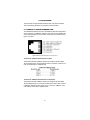
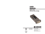
USER
MANUAL
MODEL 2124/2130
Ethernet
MicroBridge
Part# 07M2124-UM
Doc# 08306U2-001,
Rev. B
Revised 10/27/06
An ISO-9001
Certified Company
SALES OFFICE
(301) 975-1000
TECHNICAL SUPPORT
(301) 975-1007
TABLE OF CONTENTS
1.0
1.1
1.2
1.3
Warranty Information .................................................................
Radio and TV Interference............................................................
CE Notice......................................................................................
Service..........................................................................................
2.0
2.1
2.2
General Information.................................................................... 4
Features........................................................................................ 4
Description.................................................................................... 4
3.0
3.1
PPP Operational Background.................................................... 5
Applications .................................................................................. 5
4.0
4.1
Installation................................................................................... 8
Connect to 10BaseT Ethernet Port............................................... 8
Connect the 10BaseT Ethernet Port to a Hub .............................. 8
Connect the 10BaseT Ethernet Port to a PC (DTE) ..................... 8
Power Connection ........................................................................ 9
AC Power Supply (100-240VAC) ................................................. 9
DC Power ................................................................................... 10
4.2
2
2
3
3
5.0
5.1
Configuration ............................................................................
LED STATUS MONITORS .........................................................
LAN side LEDs ...........................................................................
LED Descriptions........................................................................
Power and DCE/DTE interface LEDs .........................................
A
Patton Electronics Model 2124
Specifications ........................................................................... 16
B
Patton Electronics Model 2130
Specifications ........................................................................... 17
C
2124/2130 Factory
Replacement Parts ................................................................... 18
D
10BaseT Interface Pin Assignment
(RJ-45 Female Connector)
(DTE Configuration).................................................................. 19
E
V.24 Terminal Interface Pin Assignment
(DB-25 Male Connector) .......................................................... 20
F
EIA-530 Terminal Interface Pin Assignment
(DB-25 Male Connector) .......................................................... 21
G
Power Supply Interface ............................................................ 22
1
13
13
13
14
14
1.0 WARRANTY INFORMATION
Patton Electronics warrants all Model 2124/2130 components to be free
from defects, and will—at our option—repair or replace the product
should it fail within one year from the first date of shipment.
This warranty is limited to defects in workmanship or materials, and does
not cover customer damage, abuse or unauthorized modification. If this
product fails or does not perform as warranted, your sole recourse shall
be repair or replacement as described above. Under no condition shall
Patton Electronics be liable for any damages incurred by the use of this
product. These damages include, but are not limited to, the following:
lost profits, lost savings and incidental or consequential damages arising
from the use of or inability to use this product. Patton Electronics specifically disclaims all other warranties, expressed or implied, and the installation or use of this product shall be deemed an acceptance of these
terms by the user.
1.1 RADIO AND TV INTERFERENCE
The Model 2124/2130 generates and uses radio frequency energy, and if
not installed and used properly—that is, in strict accordance with the
manufacturer’s instructions—may cause interference to radio and television reception. The Model 2124/2130 has been tested and complies
with the limits for a Class A computing device in accordance with the
specification in Subpart J of Part 15 of FCC rules, that are designed to
provide reasonable protection from such interference in a commercial
installation. However, this is no guarantee that interference will not occur
in a particular installation. If the Model 2124/2130 does cause interference to radio or television reception, which can be determined by disconnecting the unit, the user is encouraged to try to correct the interference
by one or more of the following measures: moving the computing equipment away from the receiver, re-orienting the receiving antenna and/or
plugging the receiving equipment into a different AC outlet (such that the
computing equipment and receiver are on different branches). In the
event the user detects intermittent or continuous product malfunction due
to nearby high power transmitting radio frequency equipment, the user is
strongly advised to use only a shielded twisted pair data cable that is
bonded to metalized external outer shield plugs at both ends. The use of
a shielded cable satisfies compliance with the Electromagnetic Compatibility (EMC) directive.
2
1.2 CE NOTICE
The CE symbol on your Patton Electronics equipment indicates that it is
in compliance with the Electromagnetic Compatibility (EMC) directive
and the Low Voltage Directive (LVD) of the Union European (EU). A Certificate of Compliance is available by contacting Patton Technical Support.
1.3 SERVICE
All warranty and non-warranty repairs must be returned freight prepaid
and insured to Patton Electronics. All returns must have a Return Materials Authorization (RMA) number on the outside of the shipping container. This number may be obtained from Patton Electronics Technical
Support at:
Tel:
(301) 975-1007
Email: http://www.patton.com
www: [email protected]
Note
Packages received without an RMA number will not be
accepted.
Patton Electronics’ technical staff is also available to answer any questions that might arise concerning the installation or use of your Model
2124/2130. Technical Support hours: 8AM to 5PM EST, Monday
through Friday.
WARNING! This device is not intended to be connected to the public
telephone network.
3
2.0 GENERAL INFORMATION
Thank you for your purchase of this Patton Electronics product. This
product has been thoroughly inspected and tested and is warranted for
One Year parts and labor. If any questions or problems arise during
installation or use of this product, please do not hesitate to contact Patton Electronics Technical Support at (301) 975-1007.
2.1 FEATURES
• Integral V.24 Male to 10BaseT Ethernet (Model 2124)
• Integral EIA-530 Male to 10BaseT Ethernet (Model 2130)
• Industry standard, shielded RJ-45 10BaseT connection
• 802.3 Ethernet supported by Transparent LAN bridging
• PPP Bridging Control Protocol (RFC 1638) with auto detection for
compatibility with existing Patton Bridge Modules
• 4096 MAC address table
• 1 MB RAM; 128KB FLASH
• Throughput latency of 1 frame
• Automatic LAN MAC address aging
• Nine LEDs monitor power, LAN, and DTE Interface signals
2.2 DESCRIPTION
The Patton Model 2124/2130 MicroBridge is an Ethernet Bridge that provides LAN extension when used in conjunction with a V.24 or EIA-530
DCE device, such as a DSU/CSU, NTU, or router. The Model 2124/2130
performs transparent Ethernet bridging and functions at the MAC level,
thus is transparent to higher level protocols such as TCP/IP, DECnet,
NETBIOS, and IPX network protocols. Only broadcast, multicast, or
frames set up for peered LAN are forwarded. The Model 2124/2130 is
802.3 Ethernet compliant and supports PPP Bridging Control Protocol
(RFC 1638) on the DTE side.
4
3.0 PPP OPERATIONAL BACKGROUND
PPP is a protocol used for multi-plexed transport over a point-to-point
link. PPP operates on all full duplex media, and is a symmetric peer-topeer protocol, which can be broken into three main components: 1. A
standard method to encapsulate datagrams over serial links; 2. A Link
Control Protocol (LCP) to establish, configure, and test the data-link connection; 3. A family of Network Control Protocols (NCPs) to establish and
configure different network layer protocols.
In order to establish communications over a point-to-point link, each end
of the PPP link must first announce its capabilities and agree on the
parameters of the link’s operation. This exchange is facilitated through
LCP Configure-Request packets.
Once the link has been established and optional facilities have been
negotiated, PPP will attempt to establish a network protocol. PPP will
use Network Control Protocol (NCP) to choose and configure one or
more network layer protocols. Once each of the network layer protocols
have been configured, datagrams from the established network layer
protocol can be sent over the link. The link will remain configured for
these communications until explicit LCP or NCP packets close the link
down, or until some external event occurs.
The PPP Bridging Control Protocol (BCP), defined in RFC 1638, configures and enables/disables the bridge protocol on both ends of the pointto-point link. BCP uses the same packet exchange mechanism as the
Link Control Protocol (LCP). BCP is a Network Control Protocol of PPP,
bridge packets may not be exchanged until PPP has reached the network layer protocol phase.
3.1 APPLICATIONS
In situations where a routed network requires connectivity to a remote
Ethernet network, the interface on a router can be configured as a PPP
IP Half Bridge. The serial line to the remote bridge functions as a Virtual
Ethernet interface, effectively extending the routers serial port connection to the remote network. The bridge device sends bridge packets
(BPDU's) to the router's serial interface. The router will receive the layer
three address information and will forward these packets based on its IP
address.
Figure 1 shows a typical Cisco router with a serial interface configured
as a PPP Half Bridge. The router serial interface uses a remote device
that supports PPP bridging to function as a node on the remote Ethernet
network. The serial interface on the Cisco will have an IP address on the
same Ethernet subnet as the bridge.
5
Figure 1. Cisco router with serial interface, configured as PPP Half Bridge.
For example, the customer site is assigned the addresses 192.168.1.0/
24 through 192.168.1.1/24. The address 192.168.1.1/24 is also the
default gateway for the remote network. The above settings remove any
routing/forwarding intelligence from the CPE. The associated Cisco configuration will set serial interface (s0) to accommodate half bridging for
the above example.
Authentication is optional under PPP. In a point-to-point leased-line link,
incoming customer facilities are usually fixed in nature, therefore authentication is generally not required. If the foreign device requires authentication via PAP or CHAP, the PPP software will respond with default
Peer-ID consisting of the units Ethernet MAC address and a password
which consists of the unit’s Ethernet MAC address.
Some networking systems do not define network numbers in packets
sent out over a network. If a packet does not have a specific destination
network number, a router will assume that the packet is set up for the
local segment and will not forward it to any other sub-network. However,
in cases where two devices need to communicate over the wide-area,
bridging can be used to transport non-routable protocols.
Figure 2 illustrates transparent bridging between two routers over a
serial interface (s0). Bridging will occur between the two Ethernet Interfaces on Router A (e0 and e1) and the two Ethernet Interfaces on Router
B (e0 and e1).
6
Figure 2. Transparent bridging between two routers over a serial link.
7
4.0 INSTALLATION
The 2124/2130 is equipped with Network, DTE, and power interfaces.
This section briefly describes connnection to each interface.
4.1 CONNECT TO 10BASET ETHERNET PORT
The shielded RJ-45 Ethernet port on the Model 2124/2130 is designed to
connect directly to a 10BaseT network. Figure 3 shows the 10BaseT RJ45 port pin description. You may make connections up to 300 feet using
type 4 or 5 cable.
Figure 3. Model 2124/2130 Ethernet connector pinout
Connect the 10BaseT Ethernet Port to a Hub
The Model 2124/2130 10BaseT interface is configured as DTE (Data
Terminal Equipment). Use the diagram below to construct a cable to connect the 2124/2130 to a 10BaseT Hub.
Connect the 10BaseT Ethernet Port to a PC (DTE)
The Model 2124/2130 10BaseT interface is configured as DTE (Data
Terminal Equipment). To connect the 2124/2130 to another DTE such as
a 10BaseT network interface card in a PC, construct a 10BaseT crossover cable as shown in the diagram below.
8
4.2 POWER CONNECTION
The Model 2124/2130 offers either an AC or DC power supply.
The 2124/2130 provides a strap selectable power supply.
AC Power Supply (100-240VAC)
The Model 2124/2130 uses a 5VDC, 2A universal input 100-240VAC,
power supply (center pin is +5V). The universal input power supply is
equipped with a male IEC-320 connector. This power supply connects to
the Model 2124/2130 via a barrel jack on the rear panel. A variety of
international power cords are available for the universal power supply.
The Model 2124/2130 powers up as soon as it is plugged into an AC outlet. The unit does not have a power switch.
The 2124/2130 is factory set to be used with the AC power supply.
Note
Default setting has strap on position 7 and 8 on J3 for AC power
supply. See Figure 4 below.
9
DC Power
Figure 4. Strap positions 7 and 8 on J3
Supply DC power directly to the power supply jack. DC power supplied
must be +5VDC ±5%, 500mA minimum, center positive, and can be supplied via a barrel type plug with 2.1/5.5/10mm I.D./O.D./Shaft Length
dimensions. For this powering option, set J3 to position 7 and 8 as
shown in figure 4 (factory default).
The 36-60 VDC DC to DC adapter is supplied with the DC version of the
Model 2124/2130. The black and red leads plug into a DC source (nominal 48VDC) and the barrel power connector plugs into the barrel power
supply jack on the 2124/2130. See Figure 5 below. For this powering
option, set J3 to position 7 and 8 as shown in figure 4 (factory default).
DC power (+5VDC) can also be supplied via pins 21 or 25 on the DB-25
connector for the Model 2124. DC power (+5VDC) can also be supplied
via pins 21 or 25 on the DB-25 connector for the Model 2130.
1.0A
0.2A MAX
SWITCHING POWER SUPPLY
INPUT : 36-60V
MODEL : SYD1106-0505
OUTPUT : +5V
MADE IN CHINA BY SUNNY
S/N: G01234567890
Barrel power connector
OUTPUT POWER : 5W MAX
To Power
Supply Jack
-Vin
To -48VDC
Source
Black lead (-V)
Red lead (+V)
+Vin
Figure 5. Connecting DC Power to the 2124/2130 DC Power Supply.
10
WARNING
There are no user-serviceable parts in the power
supply section of the Model 2124/2130. For more
information, please contact Patton Electronics
Technical support at (301) 975-1007, via our web
site at http://www.patton.com, or by e-mail at
[email protected].
Power-up 2124 via DB-25 Connector on Pin 25
Place strap position 1 and 2 on J3 for DC power supply. See Figure 6
below.
Power-up 2130 via DB-25 Connector on Pin 25
Place strap position 1 and 2 on J3 for DC power supply. See Figure 6
below.
Figure 6. Strap positions 1 and 2 on J3
Power-up 2124 via DB-25 Connector on Pin 21
Place strap position 3 and 4 on J3 for DC power supply. See Figure 7
below.
Power-up 2130 via DB-25 Connector on Pin 21
Place strap position 3 and 4 on J3 for DC power supply. See Figure 7
below.
11
Figure 7. Strap positions 3 and 4 on J3
12
5.0 CONFIGURATION
All configuration is done through software auto-detection for the Model
2124/2130. Once you have configured your mux or other equipment to
be connected to the 2124/2130, the unit is ready for operation. Observe
that the serial port of the 2124/2130 is configured as a DTE and must
connect to a DCE.
The LAN port also requires no configuration to connect to a 10BaseT
Ethernet.
Note
The V.24 and EIA-530 Interface is configured as a DTE. The
2124/2130 will transmit and receive data to and from the DCE,
based on the speed of the clocks received from the DCE. On the
LAN side interface, data is sent and received in burst mode at
10Mbps.
5.1 LED STATUS MONITORS
The 2124/2130 uses two LEDs on the Ethernet connection side. A green
LED indicates that link connection to the network is established. The yellow LED displays status codes (See section 5.1.2 for status code information).
Seven, low power, LEDs located on the top of the 2124/2130 case indicate POWER and V.24 or EIA-530 signal activity.
LAN side LEDs
The Model 2124/2130 features two LAN LEDs that monitor general operation status and the 10BaseT twisted pair link integrity. Figure 8 shows
the LEDs located at the rear of the Model 2124/2130. Following Figure 8
is a description of each LED function. Figure 8 shows the LEDs located
on the top of the Model 2124/2130.
13
LED Descriptions
Figure 8. 2124/2130 rear view
The status LED blinks yellow from one to eleven times to indicate system
status. Each pulse pattern is separated by a 2 second "off " period.
Greater pulse patterns have higher priority (buffer saturation has greater
priority than an empty MAC table).
Valid system statuses are:
1 pulse
2 pulses
3 pulses
=
=
=
4 pulses
5 pulses
6 pulses
7 pulses
8 pulses
9 pulses
10 pulses
11 pulses
=
=
=
=
=
=
=
=
system status ok
No MAC entries in the MAC address table
Clear to send (CTS) or Carrier Detect (DCD) from
base unit are not asserted
IMRC2/IA buffer is saturated
WAN receive frame(s) too large
WAN receive frame(s) not Octet aligned
WAN receive frame(s) aborted
Detected WAN receive frame(s) with bad CRC
Detected LAN receive frame(s) too large
Detected LAN receive frame(s) not Octet aligned
Detected LAN receive frame(s) with bad CRC
After a status code is displayed eight times and the associated condition
is removed, the status code will no longer appear.
The link LED glows green to indicate link integrity on the 10BaseT
twisted pair line.
Power and DCE/DTE interface LEDs
Seven LEDs indicate POWER and DTE/DCE activity on the front of the
2124/2130.
14
Figure 9. Front of Model 2124/2130, showing LED indicators
TXD- Trasmit data LED (green) blinks to indicate data transitions and
remains OFF when no data is transmitted (idle).
RXD- Received data LED (green) blinks to indicate data transitions and
remains OFF when no data is received (idle).
DTR- Control LED (yellow)- turns ON at power up to indicate to the DCE
that the 2124 is active.
CTS- Indication LED (yellow) - turns ON when the 2124 is ready to
receive data from the DCE.
DCD- Status LED (yellow) - Turns ON to indicate that a carrier detect
signal is received from the DCE.
CLK- Clock Signal LED (yellow) - blinks to indicate that the transmit
clock from the DCE is active. The CLK LED will remain OFF to indicate
the absence of the transmit clock.
PWR- LED (green) turns ON as soon as power is applied to the 2124/
2130.
15
APPENDIX A
PATTON ELECTRONICS MODEL 2124
SPECIFICATIONS
LAN Connection:
DTE connection:
Protocol:
MAC Address Table Size:
MAC Address Aging:
On-board Memory:
Frame Latency:
LEDs LAN Side:
LEDs DTE Side:
Power supply Input:
Power Consumption:
Humidity:
Temperature:
Dimensions:
Compliance:
RJ-45, 10BaseT, 802.3 Ethernet supported
by Transparent LAN bridging
DB-25 connector, V.24 (DTE orientation)
PPP (RFC 1661) with Bridging Control Protocol (RFC 1638)
4096 entries
MAC addresses deleted after eight minutes
inactivity
1 MB RAM; 128 KB FLASH
1 frame
(1) yellow, general status; (1) green, link
integrity
TXD, RXD and Power, (green);
DTR,CTS,DCD, and CLK (Yellow)
100-240VAC, 50-60Hz, 0.4A
500mA @ 5VDC
Up to 90% non-condensing
0 -50 C
9.0 x 5.3 x 2.0 cm (3.5"L x 2.1"W x 0.78"H)
FCC Part 15A
CE Mark per EEC Directive
89/336/EEC
Low Voltage Directive
16
APPENDIX B
PATTON ELECTRONICS MODEL 2130
SPECIFICATIONS
LAN Connection:
DTE connection:
Protocol:
MAC Address Table Size:
MAC Address Aging:
On-board Memory:
Frame Latency:
LEDs LAN Side:
LEDs DTE Side:
Power supply Input:
Power Consumption:
Humidity:
Temperature:
Dimensions:
Compliance:
RJ-45, 10BaseT, 802.3 Ethernet supported by Transparent LAN bridging
DB-25 connector, EIA-530 (DTE orientation)
PPP (RFC 1661) with Bridging Control
Protocol (RFC 1638)
4096 entries
MAC addresses deleted after eight minutes inactivity
1 MB RAM; 128 KB FLASH
1 frame
(1) yellow, general status; (1) green, link
integrity
TD, RD and Power, (green); DTR DCD,
CTS and CLK, (Yellow)
100-240VAC, 50-60Hz, 0.4A
500mA @ 5VDC
Up to 90% non-condensing
0 -50 C
9.0 x 5.3 x 2.0 cm (3.5"L x 2.1"W x 0.78"H)
FCC Part 15A
CE Mark per EEC Directive
89/336/EEC
Low Voltage Directive 73/23/EEC
17
APPENDIX C
2124/2130 FACTORY
REPLACEMENT PARTS
Part #
07M2121/2135C
0805DCUI
Description
2124/2130 User Manual
100-250 VAC Universal Power Supply
18
APPENDIX D
10BASET INTERFACE PIN ASSIGNMENT
(RJ-45 FEMALE CONNECTOR)
(DTE CONFIGURATION)
Pin #
1 TD +
2 TD 3 RD +
4
5
6 RD 7
8
Signal
(data output from 2124/2130)
(data output from 2124/2130)
(data input to 2124/2130)
no connection
no connection
(data input to 2124/2130)
no connection
no connection
19
APPENDIX E
V.24 TERMINAL INTERFACE PIN ASSIGNMENT
(DB-25 MALE CONNECTOR)
Pin #
1
2
3
4
5
7
8
15
17
20
21
25
Signal
Shield GND/Frame GND
TD
RD
RTS
CTS
SIG GND
CD
TX CLK
RCV CLK
DTR
DC Power (+5VDC)
DC Power (+5DC)
20
APPENDIX F
EIA-530 TERMINAL INTERFACE PIN ASSIGNMENT
(DB-25 MALE CONNECTOR)
Pin#
1
2
3
4
5
7
8
9
10
12
13
14
15
16
17
19
20
21
23
25
Signal
Shield GND/Frame GND
TD A
RD A
RTS A
CTS A
SIG GND
CD A
RCV CLK B
CD B
TX CLK B
CTS B
TD B
TX CLK A
RD B
RCV CLK A
RTS B
DTR A
+5VDC
DTR B
+5VDC
21
APPENDIX G
POWER SUPPLY INTERFACE
Via 5VDC power jack (J1)
Center Pin: +5VDC @ 500 mA minimun
Outer Barrel: Ground
22
Notes
_________________________________________________________
_________________________________________________________
_________________________________________________________
_________________________________________________________
_________________________________________________________
_________________________________________________________
_________________________________________________________
_________________________________________________________
_________________________________________________________
_________________________________________________________
_________________________________________________________
_________________________________________________________
_________________________________________________________
_________________________________________________________
_________________________________________________________
_________________________________________________________
_________________________________________________________
_________________________________________________________
_________________________________________________________
_________________________________________________________
_________________________________________________________
Copyright © 2006
Patton Electronics Company
All Rights Reserved
23