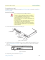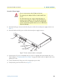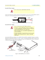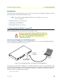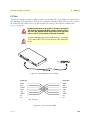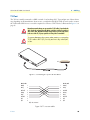
1
For Quick
Start Installation
OnSite 2884
T1/E1 Channelized Gigabit Router
User Manual
Important
This is a Class A device and is intended for use in a light industrial environment. It is not intended nor approved for use in an industrial
or residential environment.
Sales Office: +1 (301) 975-1000
Technical Support: +1 (301) 975-1007
E-mail: [email protected]
WWW: www.patton.com
Part Number: 07M2884-GS, Rev. E
Revised: February 23, 2012
Patton Electronics Company, Inc.
7622 Rickenbacker Drive
Gaithersburg, MD 20879 USA
Tel: +1 (301) 975-1000
Fax: +1 (301) 869-9293
Support: +1 (301) 975-1007
Web: www.patton.com
E-mail: [email protected]
Trademark Statement
The term OnSite is a trademark of Patton Electronics Company. All other trademarks
presented in this document are the property of their respective owners.
Copyright © 2012, Patton Electronics Company. All rights reserved.
The information in this document is subject to change without notice. Patton Electronics assumes no liability for errors that may appear in this document.
Important Information
To use virtual private network (VPN) and/or AES/DES/3DES encryption capabilities
with the OnSite 2884, you may need to purchase additional licenses, hardware, software, network connection, and/or service. Contact [email protected] or
+1 (301) 975-1000 for assistance.
Warranty Information
The software described in this document is furnished under a license and may be used
or copied only in accordance with the terms of such license. For information about the
license, see Appendix E, "End user license agreement" on page 49 or go to
www.patton.com.
Patton Electronics warrants all OnSite router components to be free from defects, and
will—at our option—repair or replace the product should it fail within one year from
the first date of the shipment.
This warranty is limited to defects in workmanship or materials, and does not cover
customer damage, abuse or unauthorized modification. If the product fails to perform
as warranted, your sole recourse shall be repair or replacement as described above.
Under no condition shall Patton Electronics be liable for any damages incurred by the
use of this product. These damages include, but are not limited to, the following: lost
profits, lost savings and incidental or consequential damages arising from the use of or
inability to use this product. Patton Electronics specifically disclaims all other warranties, expressed or implied, and the installation or use of this product shall be deemed
an acceptance of these terms by the user.
Summary Table of Contents
1 General information ...................................................................................................................................... 13
2 Applications overview.................................................................................................................................... 19
3 OnSite installation ........................................................................................................................................ 21
4 Initial configuration ...................................................................................................................................... 28
5 Contacting Patton for assistance ................................................................................................................... 32
A Compliance information .............................................................................................................................. 35
B Specifications ................................................................................................................................................ 38
C Cabling ......................................................................................................................................................... 41
D Port pin-outs ................................................................................................................................................ 46
E End user license agreement ........................................................................................................................... 49
3
Table of Contents
Summary Table of Contents ........................................................................................................................... 3
Table of Contents ........................................................................................................................................... 4
List of Figures ................................................................................................................................................. 7
List of Tables .................................................................................................................................................. 8
About this guide ............................................................................................................................................. 9
Audience................................................................................................................................................................. 9
Structure................................................................................................................................................................. 9
Precautions ........................................................................................................................................................... 10
Safety when working with electricity ...............................................................................................................11
General observations .......................................................................................................................................12
Typographical conventions used in this document................................................................................................ 12
General conventions .......................................................................................................................................12
1 General information ...................................................................................................................................... 13
OnSite Model 2884 Overview...............................................................................................................................14
Features and Benefits.............................................................................................................................................15
Model 2884 Features ......................................................................................................................................15
Rear and Front Panels ...........................................................................................................................................16
OnSite 2884 rear panel ...................................................................................................................................16
OnSite 2884 front panel .................................................................................................................................18
2 Applications overview.................................................................................................................................... 19
Typical OnSite 2884 Application ..........................................................................................................................20
3 OnSite installation ........................................................................................................................................ 21
Planning the installation........................................................................................................................................22
Site log ............................................................................................................................................................22
Network information ......................................................................................................................................22
Network Diagram ...........................................................................................................................................22
IP related information .....................................................................................................................................23
Software tools .................................................................................................................................................23
Power source ...................................................................................................................................................23
Location and mounting requirements .............................................................................................................23
Installing the OnSite 2884 ....................................................................................................................................23
Placing the OnSite ..........................................................................................................................................23
Installing cables ...............................................................................................................................................24
Connecting the T1/E1 ports .....................................................................................................................24
Connecting the 10/100/1000Base-T Ethernet LAN and WAN cables ......................................................24
Connecting the power supply ....................................................................................................................25
Internal AC Power Supply ..................................................................................................................25
External AC Power Supply .................................................................................................................26
External DC Power Supply .................................................................................................................27
4
OnSite Model 2884 User Manual
Table of Contents
Internal DC Power Supply. ................................................................................................................27
4 Initial configuration ...................................................................................................................................... 28
Introduction ..........................................................................................................................................................29
1. Connecting the OnSite to your PC ...................................................................................................................29
Connecting and logging in via the Ethernet port .............................................................................................29
Connecting and logging in via the Console port .............................................................................................30
2. Configuring the desired IP address ....................................................................................................................30
Factory-default IP settings ...............................................................................................................................30
Login ..............................................................................................................................................................31
Changing the IP address .................................................................................................................................31
3. Connecting the OnSite to the network..............................................................................................................31
5 Contacting Patton for assistance ................................................................................................................... 32
Introduction ..........................................................................................................................................................33
Contact information..............................................................................................................................................33
Patton support headquarters in the USA .........................................................................................................33
Alternate Patton support for Europe, Middle East, and Africa (EMEA) ..........................................................33
Warranty Service and Returned Merchandise Authorizations (RMAs)...................................................................33
Warranty coverage ..........................................................................................................................................33
Out-of-warranty service .............................................................................................................................34
Returns for credit ......................................................................................................................................34
Return for credit policy .............................................................................................................................34
RMA numbers ................................................................................................................................................34
Shipping instructions ................................................................................................................................34
A Compliance information .............................................................................................................................. 35
Compliance ...........................................................................................................................................................36
EMC ...............................................................................................................................................................36
Safety ..............................................................................................................................................................36
PSTN Regulatory ............................................................................................................................................36
Radio and TV Interference ....................................................................................................................................36
FCC Part 68 (ACTA) Statement ...........................................................................................................................36
Industry Canada Notice ........................................................................................................................................37
CE Declaration of Conformity ..............................................................................................................................37
Authorized European Representative .....................................................................................................................37
B Specifications ................................................................................................................................................ 38
WAN Ports ...........................................................................................................................................................39
Ethernet Ports .......................................................................................................................................................39
Management .........................................................................................................................................................39
Protocols ...............................................................................................................................................................39
Security .................................................................................................................................................................40
Power Supply ........................................................................................................................................................40
Physical .................................................................................................................................................................40
C Cabling ......................................................................................................................................................... 41
5
OnSite Model 2884 User Manual
Table of Contents
Introduction ..........................................................................................................................................................42
Console .................................................................................................................................................................42
Ethernet ................................................................................................................................................................43
E1 Port..................................................................................................................................................................44
T1 Port..................................................................................................................................................................45
D Port pin-outs ................................................................................................................................................ 46
Introduction ..........................................................................................................................................................47
Console port..........................................................................................................................................................47
Ethernet ................................................................................................................................................................48
T1/E1 port ............................................................................................................................................................48
E End user license agreement ........................................................................................................................... 49
End User License Agreement .................................................................................................................................50
1. Definitions ..................................................................................................................................................50
2. Title ............................................................................................................................................................50
3. Term ...........................................................................................................................................................50
4. Grant of License ..........................................................................................................................................50
5. Warranty ....................................................................................................................................................50
6. Termination ................................................................................................................................................51
7. Other licenses .............................................................................................................................................51
6
List of Figures
1
2
3
4
5
6
7
8
9
10
11
12
13
14
15
16
17
18
19
OnSite Model 2884 . . . . . . . . . . . . . . . . . . . . . . . . . . . . . . . . . . . . . . . . . . . . . . . . . . . . . . . . . . . . . . . . . . . . . 14
2884 rear panel . . . . . . . . . . . . . . . . . . . . . . . . . . . . . . . . . . . . . . . . . . . . . . . . . . . . . . . . . . . . . . . . . . . . . . . . . 16
OnSite 2884 front panel . . . . . . . . . . . . . . . . . . . . . . . . . . . . . . . . . . . . . . . . . . . . . . . . . . . . . . . . . . . . . . . . . . 18
Typical application for OnSite Model 2884 . . . . . . . . . . . . . . . . . . . . . . . . . . . . . . . . . . . . . . . . . . . . . . . . . . . 20
2884 rear panel . . . . . . . . . . . . . . . . . . . . . . . . . . . . . . . . . . . . . . . . . . . . . . . . . . . . . . . . . . . . . . . . . . . . . . . . . 25
Power LED . . . . . . . . . . . . . . . . . . . . . . . . . . . . . . . . . . . . . . . . . . . . . . . . . . . . . . . . . . . . . . . . . . . . . . . . . . . . 25
Power connector location on rear panel . . . . . . . . . . . . . . . . . . . . . . . . . . . . . . . . . . . . . . . . . . . . . . . . . . . . . . 26
Connecting DC Power to the 2884 DC Power Supply . . . . . . . . . . . . . . . . . . . . . . . . . . . . . . . . . . . . . . . . . . . 27
Internal 48VDC power connection . . . . . . . . . . . . . . . . . . . . . . . . . . . . . . . . . . . . . . . . . . . . . . . . . . . . . . . . . 27
Connecting the OnSite to your laptop PC via the Ethernet port . . . . . . . . . . . . . . . . . . . . . . . . . . . . . . . . . . . . 29
Connecting the OnSite to your laptop PC via the console port . . . . . . . . . . . . . . . . . . . . . . . . . . . . . . . . . . . . . 30
Connecting a serial terminal . . . . . . . . . . . . . . . . . . . . . . . . . . . . . . . . . . . . . . . . . . . . . . . . . . . . . . . . . . . . . . . 42
Typical Ethernet straight-through cable diagram for 10/100Base-T . . . . . . . . . . . . . . . . . . . . . . . . . . . . . . . . . 43
Typical Ethernet straight-through cable diagram for 1000Base-T . . . . . . . . . . . . . . . . . . . . . . . . . . . . . . . . . . . 43
Connecting an E1 port to an NT1 . . . . . . . . . . . . . . . . . . . . . . . . . . . . . . . . . . . . . . . . . . . . . . . . . . . . . . . . . . 44
E1 port crossover cable . . . . . . . . . . . . . . . . . . . . . . . . . . . . . . . . . . . . . . . . . . . . . . . . . . . . . . . . . . . . . . . . . . . 44
Connecting a T1 port to an NT device . . . . . . . . . . . . . . . . . . . . . . . . . . . . . . . . . . . . . . . . . . . . . . . . . . . . . . . 45
T1 crossover cable . . . . . . . . . . . . . . . . . . . . . . . . . . . . . . . . . . . . . . . . . . . . . . . . . . . . . . . . . . . . . . . . . . . . . . . 45
EIA-561 (RJ-45 8-pin) port . . . . . . . . . . . . . . . . . . . . . . . . . . . . . . . . . . . . . . . . . . . . . . . . . . . . . . . . . . . . . . . 47
7
List of Tables
1
2
3
4
5
6
7
8
9
General conventions . . . . . . . . . . . . . . . . . . . . . . . . . . . . . . . . . . . . . . . . . . . . . . . . . . . . . . . . . . . . . . . . . . . . . 12
OnSite 2884 Model Codes . . . . . . . . . . . . . . . . . . . . . . . . . . . . . . . . . . . . . . . . . . . . . . . . . . . . . . . . . . . . . . . . 15
Rear panel ports . . . . . . . . . . . . . . . . . . . . . . . . . . . . . . . . . . . . . . . . . . . . . . . . . . . . . . . . . . . . . . . . . . . . . . . . 17
LED Descriptions . . . . . . . . . . . . . . . . . . . . . . . . . . . . . . . . . . . . . . . . . . . . . . . . . . . . . . . . . . . . . . . . . . . . . . 18
Sample site log entries . . . . . . . . . . . . . . . . . . . . . . . . . . . . . . . . . . . . . . . . . . . . . . . . . . . . . . . . . . . . . . . . . . . . 22
Factory default IP address and network mask configuration . . . . . . . . . . . . . . . . . . . . . . . . . . . . . . . . . . . . . . . 30
RJ45 socket 10/100Base-T . . . . . . . . . . . . . . . . . . . . . . . . . . . . . . . . . . . . . . . . . . . . . . . . . . . . . . . . . . . . . . . . 48
RJ45 socket 1000Base-T . . . . . . . . . . . . . . . . . . . . . . . . . . . . . . . . . . . . . . . . . . . . . . . . . . . . . . . . . . . . . . . . . . 48
RJ-45 socket . . . . . . . . . . . . . . . . . . . . . . . . . . . . . . . . . . . . . . . . . . . . . . . . . . . . . . . . . . . . . . . . . . . . . . . . . . . 48
8
About this guide
This guide describes the OnSite 2884 hardware, installation and basic configuration.
Audience
This guide is intended for the following users:
• Operators
• Installers
• Maintenance technicians
Structure
This guide contains the following chapters and appendices:
•
•
•
•
•
•
•
•
•
•
Chapter 1 on page 13 provides information about router features and capabilities
Chapter 2 on page 19 contains an overview describing router operation and applications
Chapter 3 on page 21 provides hardware installation procedures
Chapter 4 on page 28 provides quick-start procedures for configuring the OnSite router
Chapter 5 on page 32 contains information on contacting Patton technical support for assistance
Appendix A on page 35 contains compliance information for the router
Appendix B on page 38 contains specifications for the routers
Appendix C on page 41 provides cable recommendations
Appendix D on page 46 describes the router’s ports and pin-outs
Appendix E on page 49 provides license information that describes acceptable usage of the software provided with the OnSite 2884
For best results, read the contents of this guide before you install the router.
9
OnSite Model 2884 User Manual
Precautions
Notes, cautions, and warnings, which have the following meanings, are used throughout this guide to help you
become aware of potential problems. Warnings are intended to prevent safety hazards that could result in personal injury. Cautions are intended to prevent situations that could result in property damage or
impaired functioning.
Note
A note presents additional information or interesting sidelights.
The alert symbol and IMPORTANT heading calls attention to
important information.
IMPORTANT
The alert symbol and CAUTION heading indicate a potential hazard. Strictly follow the instructions to avoid property damage.
CAUTION
The shock hazard symbol and CAUTION heading indicate a
potential electric shock hazard. Strictly follow the instructions to
avoid property damage caused by electric shock.
CAUTION
The alert symbol and WARNING heading indicate a potential safety hazard.
Strictly follow the warning instructions to avoid personal injury.
WARNING
WARNING
The shock hazard symbol and WARNING heading indicate a potential electric
shock hazard. Strictly follow the warning instructions to avoid injury caused
by electric shock.
10
OnSite Model 2884 User Manual
Safety when working with electricity
WARNING
WARNING
WARNING
WARNING
The OnSite contains no user serviceable parts. The equipment shall be
returned to Patton Electronics for repairs, or repaired by qualified
service personnel.
Mains Voltage: Line voltages are present when the power cord is connected.
The mains outlet shall be within 10 feet (3 meters) of the device, shall be
easily accessible, and protected by a circuit breaker.
For AC powered units, ensure that the power cable used meets all applicable
standards for the country in which it is to be installed, and that it is connected
to a wall outlet which has earth ground.
Hazardous network voltages are present in WAN ports regardless of whether
power to the OnSite is ON or OFF. To avoid electric shock, use caution when
near WAN ports. When detaching cables, detach the end away from the
OnSite first.
Do not work on the system or connect or disconnect cables during periods of
lightning activity.
WARNING
For units with an external power adapter, the adapter shall be a listed Limited Power Source.
WARNING
WARNING
Ensure that the power cable shipped with this device meets all applicable
standards for the country in which it is to be installed. If it is not, refer to
chapter Chapter 5, “Contacting Patton for assistance” on page 32 for
help in replacing it with a compliant cable.
In accordance with the requirements of council directive 2002/
96/EC on Waste of Electrical and Electronic Equipment (WEEE),
ensure that at end-of-life you separate this product from other
waste and scrap and deliver to the WEEE collection system in
your country for recycling.
11
OnSite Model 2884 User Manual
General observations
• Clean the case with a soft slightly moist anti-static cloth
• Place the unit on a flat surface and ensure free air circulation
• Avoid exposing the unit to direct sunlight and other heat sources
• Protect the unit from moisture, vapors, and corrosive liquids
Typographical conventions used in this document
This section describes the typographical conventions and terms used in this guide.
General conventions
The procedures described in this manual use the following text conventions:
Table 1. General conventions
Convention
Garamond blue type
Meaning
Indicates a cross-reference hyperlink that points to a figure, graphic, table, or section heading. Clicking on the hyperlink jumps you to the reference. When you
have finished reviewing the reference, click on the Go to Previous View
button
in the Adobe® Acrobat® Reader toolbar to return to your starting point.
Futura bold type
Commands and keywords are in boldface font.
Futura bold-italic type
Parts of commands, which are related to elements already named by the user, are
in boldface italic font.
Italicized Futura type
Variables for which you supply values are in italic font
Futura type
Indicates the names of fields or windows.
Garamond bold type
Indicates the names of command buttons that execute an action.
<>
Angle brackets indicate function and keyboard keys, such as <SHIFT>, <CTRL>,
<C>, and so on.
[]
Elements in square brackets are optional.
{a | b | c}
Alternative but required keywords are grouped in braces ({ }) and are separated
by vertical bars ( | )
screen
Terminal sessions and information the system displays are in screen font.
node
The leading IP address or nodename of a OnSite is substituted with node in
boldface italic font.
SN
The leading SN on a command line represents the nodename of the OnSite
#
An hash sign at the beginning of a line indicates a comment line.
12
Chapter 1
General information
Chapter contents
IpLink Model 2884 Overview ...............................................................................................................................14
Features and Benefits.............................................................................................................................................15
Model 2884 Features ......................................................................................................................................15
Rear and Front Panels ...........................................................................................................................................16
IpLink 2884 rear panel ...................................................................................................................................16
IpLink 2884 front panel ..................................................................................................................................18
13
OnSite Model 2884 User Manual
1 • General information
OnSite Model 2884 Overview
The Model 2884 Series T1/E1 Channelized Gigabit Routers (figure 1) are a family of multi-media routers that
terminate up to 124 PPP channels as well as perform Layer 2 bonding of T1/E1 WAN ports with multi-link
PPP. Dual Gigabit Ethernet ports ensure connection to any LAN infrastructure.
The OnSite™ Channelized Gigabit Routers offer pre-set priorities for voice and video traffic on a per port
basis up to a user configurable bandwidth. QoS configurations ease the bandwidth management of ports and
applications through the creation of QoS classes and profiles. Traffic can be shaped and policed to provide full
QoS control over both the egress and ingress directions. ToS/DiffServ bits can be re-striped to ensure networkwide QoS enforcement. VLAN priority bits can be used for QoS enforcement.
Stateful Firewall inspection of traffic is accomplished through the creation of Access Control Lists (ACLs) that
enable the filtering of traffic based on numerous criteria including source and destination IP address, port and
protocol.
Logical and physical ports are selectable for bridging or routing. Advanced IP features such NAT/NAPT and
VLANs are likewise configurable on a per port basis. By supporting the latest version of PPP/BCP, the OnSite
transparently negotiates the passing of VLAN traffic over PPP based WAN links. Bridged traffic can be tagged
and prioritized according to user defined parameters.
The 2884 Model Series boasts easy installation, offering CLI configuration via Console/VT-100 or Telnet/SSH, and HTTP web based management, and SNMP. Patton's series of high-speed access routers offer the
versatility and reliability demanded for business-class applications at the most affordable price..
Figure 1. OnSite Model 2884
OnSite Model 2884 Overview
14
OnSite Model 2884 User Manual
1 • General information
Features and Benefits
The OnSite 2884 series consists of two models (table 2). They differ in the number of T1/E1 ports and supported features. All models come equipped with two Gigabit 10/100/1000Base-T Ethernet ports.
Table 2. OnSite 2884 Model Codes
Model
T1/E1 Ports
2884/2/UI
2
2884/4/UI
4
Model 2884 Features
• 2/4 port Channelized T1/E1--Support up to 124 PPP sessions with up to 4 channelized T1/E1 ports.
• ML-PPP Expands Bandwidth--Bind any number of channels or T1/E1 ports to create up to an 8Mbps
WAN link.
• Dual Gigabit Ethernet Ports--With Dual 10/100/1000, auto-MDI ports easily connect to any LAN infrastructure.
• Per Flow QoS--Traffic rates are set through ACLs that shape and police VLAN and IP traffic.
• Stateful Firewall Inspection--Stateful firewall inspection is accomplished through ACLs that filter by
source and destination IP address, IP port and protocol.
• Layer 2/3 Traffic Filtering--Assign an ACL to any interface and filter an IP port, VLAN ID or priority bits,
and MAC addresses.
• VLAN Tagging--VLAN tagging and processing is configurable on any T1/E1 channel or Ethernet port.
• Easy Management--Easily manage the 2884 router via an HTTP/web interface, a CLI accessible via the
VT100 console or through Telnet/SSH, via SNMP, or via CORBA.
Features and Benefits
15
OnSite Model 2884 User Manual
1 • General information
Rear and Front Panels
OnSite 2884 rear panel
The OnSite 2884 rear panel ports are described in table 3.
12
0-2 Po
40 we
V, r
50
/60
0
Hz
,1
A
1
Power
(~120–240V, 50/60 Hz, 1A)
2
T1
/E
1
3
T1/E1
Ports 0-3
ET
H
0
ET
H
1
Reset
ETH 0
10/100/1000Base-T port
Co
ns
ole
RS
-23
2
ETH 1
10/100/1000Base-T port
RESET
button
Console
RS-232 port
Figure 2. 2884 rear panel
Rear and Front Panels
16
OnSite Model 2884 User Manual
1 • General information
Table 3. Rear panel ports
Port
Description
LAN ETH 0
Auto-MDX Gigabit-Ethernet port, RJ-45, connects the unit to an Ethernet WAN device
(for example, a cable modem or fiber modem). Note: Only full duplex modes are
supported.
LAN ETH 1
Auto-MDX Gigabit-Ethernet port, RJ-45, connect the unit to an Ethernet LAN (for
example, a PC, printer, or wireless bridge). Note: Only full duplex modes are supported.
T1/E1 0
RJ-45 connector providing E1 (2.048Mbps) or T1(1.533 Mbps) T1/E1 interface,
meeting all requirements of ITU-T recommendations for G.703. Use a shielded E1 or
T1 interface cable for 120 Ohm balanced connections to connect the OnSite with
an NT or ET, e.g. a PBX or LE.
T1/E1 1
RJ-45 connector providing E1 (2.048Mbps) or T1(1.533 Mbps) T1/E1 interface,
meeting all requirements of ITU-T recommendations for G.703. Use a shielded E1 or
T1 interface cable for 120 Ohm balanced connections to connect the OnSite with
an NT or ET, e.g. a PBX or LE.
T1/E1 2
RJ-45 connector providing E1 (2.048Mbps) or T1(1.533 Mbps) T1/E1 interface,
meeting all requirements of ITU-T recommendations for G.703. Use a shielded E1 or
T1 interface cable for 120 Ohm balanced connections to connect the OnSite with
an NT or ET, e.g. a PBX or LE.
T1/E1 3
RJ-45 connector providing E1 (2.048Mbps) or T1(1.533 Mbps) T1/E1 interface,
meeting all requirements of ITU-T recommendations for G.703. Use a shielded E1 or
T1 interface cable for 120 Ohm balanced connections to connect the OnSite with
an NT or ET, e.g. a PBX or LE.
Console
Used for service and maintenance, the Console port, an RS-232 RJ-45 connector,
connects the product to a serial terminal such as a PC or ASCII terminal (also called
a dumb terminal).
100-240 VAC 5060 Hz
Electricity supply socket for mains power cable.
Rear and Front Panels
17
OnSite Model 2884 User Manual
1 • General information
OnSite 2884 front panel
Figure 3 shows OnSite 2884 LEDs, the LED definitions are listed in table 4.
Port 0
Port 1
Port 2
Port 3
Mo
T1
/E1
Ch
de
an
l2
ne
lize
88
dG
4 Ip
iga
bit
Lin
k
Ro
ute
r
0
rt
Po
Po
Power
rt
1
Po
rt
2
Po
rt
3
Model 2884/2888 IpLink
T1/E1 Port 3
Activity
T1/E1 Port 2
Ethernet 1
Activity
Ethernet 0
Link
Ethernet 0
1000
Ethernet 0
100
Ethernet 1
Link
Ethernet 0
Activity
T1/E1 Port 1
Ethernet 1
1000
T1/E1 Port 0
Ethernet 1
100
Figure 3. OnSite 2884 front panel
Table 4. LED Descriptions
LED
Description
Note
If an error occurs, all LEDs will flash once per second.
Power
When lit, indicates power is applied.
Run
When lit, the unit is in normal operation. Flashes once per second during
boot (startup).
Ethernet Link
On when the Ethernet connection on the corresponding port has a link indication.
Ethernet Speed
10/100
When the Ethernet Link LED is on, then:
• On when the Ethernet is connected to a 100Mb network.
• Off when the Ethernet is connected to a 10Mb network.
Ethernet Speed
1000
On when the Ethernet is connected to a 1000Mb network.
Ethernet Activity
• Flashes when data is received or transmitted at the corresponding Ethernet port.
• On = in frame, no errors
T1/E1 Link/Status
• Flash = Error
• Fast Flash = Signal detected but no frame synchronization or aquisition is in
process
• Slow Flash = Framing synchronized, Signaling not established
Rear and Front Panels
18
Chapter 2
Applications overview
Chapter contents
Typical IPLink 2884 Application ..........................................................................................................................20
19
OnSite Model 2884 User Manual
2 • Applications overview
Typical OnSite 2884 Application
Available in two and four-port T1/E1 versions, the OnSite Channelized Gigabit Ethernet Router comes standard with Dual Gigabit Ethernet ports and maximizes the use of the up-link networks, minimizing the cost of
deploying service by implementing per TDM channel bridging or routing as well as supporting Layer 2 bonding of WAN interfaces into high bandwidth logical ports. For bandwidth hungry applications, traffic from
both T1/E1 ports can be bonded together using multi-link PPP. For networks with many remote locations up
to 124 remote sites can be supported with PPP.
Figure 4. Typical application for OnSite Model 2884
Typical OnSite 2884 Application
20
Chapter 3
OnSite installation
Chapter contents
Planning the installation........................................................................................................................................22
Site log ............................................................................................................................................................22
Network information ......................................................................................................................................22
Network Diagram ...........................................................................................................................................22
IP related information .....................................................................................................................................23
Software tools .................................................................................................................................................23
Power source ...................................................................................................................................................23
Location and mounting requirements .............................................................................................................23
Installing the IpLink 2884.....................................................................................................................................23
Placing the IpLink ..........................................................................................................................................23
Installing cables ...............................................................................................................................................24
Connecting the T1/E1 ports .....................................................................................................................24
Connecting the 10/100/1000Base-T Ethernet LAN and WAN cables ......................................................24
Connecting the power supply ....................................................................................................................25
Internal AC Power Supply................................................................................................................... 25
External AC Power Supply .................................................................................................................. 26
External DC Power Supply ................................................................................................................. 27
Internal DC Power Supply. ................................................................................................................. 27
21
OnSite Model 2884 User Manual
3 • OnSite installation
Planning the installation
Before installing the gateway router device, the following tasks should be completed:
• Create a network diagram (see section “Network information” on page 22)
• Gather IP related information (see section “IP related information” on page 23 for more information)
• Install the hardware and software needed to configure the OnSite. (See section “Software tools” on
page 23)
• Verify power source reliability (see section “Power source” on page 23).
After you have finished preparing for gateway router installation, go to section “Installing the IpLink 2884” on
page 23 to install the device.
Site log
Patton recommends that you maintain a site log to record all actions relevant to the system, if you do not
already keep such a log. Site log entries should include information such as listed in table 5.
Table 5. Sample site log entries
Entry
Description
Installation
Make a copy of the installation checklist and insert it into the site log
Upgrades and maintenance
Use the site log to record ongoing maintenance and expansion history
Configuration changes
Record all changes and the reasons for them
Maintenance
Schedules, requirements, and procedures performed
Comments
Notes, and problems
Software
Changes and updates to software
Network information
Network connection considerations that you should take into account for planning are provided for several
types of network interfaces are described in the following sections.
Network Diagram
Draw a network overview diagram that displays all neighboring IP nodes, connected elements and
telephony components.
Planning the installation
22
OnSite Model 2884 User Manual
3 • OnSite installation
IP related information
Before you can set up the basic IP connectivity for your OnSite 2884 you should have the following information:
• IP addresses used for Ethernet LAN and WAN ports
• Subnet mask used for Ethernet LAN and WAN ports
• Login and password for PPPoE Access
• IP addresses of central TFTP server used for configuration upload and download (optional)
Software tools
You will need a PC (or equivalent) with Windows Telnet or a program such as Tera Term Pro Web to configure the software on your OnSite router.
You may also use a web browser to configure the software using the built-in web management interface.
Power source
If you suspect that your AC power is not reliable, for example if room lights flicker often or there is machinery
with large motors nearby, have a qualified professional test the power. Patton recommends that you include an
uninterruptible power supply (UPS) in the installation to ensure that VoIP service is not impaired if the
power fails.
Location and mounting requirements
The OnSite router is intended to be placed on a desktop or similar sturdy, flat surface that offers easy access to
the cables. Allow sufficient space at the rear of the chassis for cable connections. Additionally, you should consider the need to access the unit for future upgrades and maintenance.
Note
Under the rack mount option, the chassis can be equipped with rack mount
ears that allow for use in a 19” rack.
Installing the OnSite 2884
OnSite hardware installation consists of the following:
• Placing the device at the desired installation location (see section “Placing the IpLink” on page 23)
• Connecting the interface and power cables (see section “Installing cables”)
When you finish installing the OnSite, go to chapter 4, “Initial configuration” on page 28.
Placing the OnSite
Place the unit on a desktop or similar sturdy, flat surface that offers easy access to the cables. The unit should
be installed in a dry environment with sufficient space to allow air circulation for cooling.
Note
For proper ventilation, leave at least 2 inches (5 cm) to the left, right, front,
and rear of the unit.
Installing the OnSite 2884
23
OnSite Model 2884 User Manual
3 • OnSite installation
Installing cables
Do not work on the system or connect or disconnect cables during periods of
lightning activity.
WARNING
Connect the cables in the following order:
CAUTION
The interconnecting cables shall be acceptable for external use
and shall be rated for the proper application with respect to voltage, current, anticipated temperature, flammability, and
mechanical serviceability.
1. Connect the T1/E1 cables to the T1/E1 ports (see Appendix C on page 41 and Appendix D on page 46).
2. Connect the 10/100/1000Base-T Ethernet LAN and WAN (see section “Connecting the
10/100/1000Base-T Ethernet LAN and WAN cables” on page 24)
3. Connect the power mains cable (see section “Connecting the power supply” on page 25)
Connecting the T1/E1 ports
The OnSite comes with one to four T1/E1 ports. These ports are usually connected to a T1/E1 TDM service.
Each T1/E1 port is a RJ-48C receptacle. In most cases, a straight-through RJ-45 can be used to connect the port.
To connect the twisted pair cable to the T1/E1 port:
1. Attach the male connector of the twisted pair cable to the female connector on the OnSite.
2. Attach the other end of the cable to the serial connector on the local T1/E1 unit.
For details on the T1/E1 port pin-out and ISDN cables, refer to Appendix C, “Cabling” on page 43 and
Appendix D, “port pin-outs” on page 47.
Connecting the 10/100/1000Base-T Ethernet LAN and WAN cables
The OnSite 2884 has automatic MDX (auto-crossover) detection and configuration on all Ethernet ports. Any
of the ports can be connected to a host or hub/switch with a straight-through or cross-over wired cable.
1. Connect to the subscriber port of the broadband access modem (Cable, WLL) to ETH 0/0.
Note
The OnSite Ethernet ports operate in Full Duplex mode only. Do not connect
to Half Duplex ports. For best results, use auto-negotiation. Auto negotiation
is mandatory when using 1000BaseT (Gigabit) Ethernet.
2. Connect port ETH 0/1 to your LAN.
For details on the Ethernet port pinout and cables, refer to Appendix C, “Cabling” on page 41 and Appendix
D, “Port pin-outs” on page 46.
Installing the OnSite 2884
24
OnSite Model 2884 User Manual
3 • OnSite installation
Connecting the power supply
The 2884 has the option of an internal or external Internal AC Power Supply, or an internal or external External DC Power Supply.
Internal AC Power Supply.
• Do not connect power to the AC Mains at this time.
• There are no user-serviceable parts in the power supply sec
WARNING
tion of the Model 2884. Contact Patton Electronics Technical
support at (301)975-1007, via our web site at
http://www.patton.com, or by e-mail at [email protected],
for more information.
• The internal power supply automatically adjusts to accept an
input voltage from 100 to 240 VAC (50/60 Hz).
Verify that the proper voltage is present before plugging the
power cord into the receptacle. Failure to do so could result in
equipment damage.
1. Insert the female end of the AC power to the mains port.
12
0-2 Po
40 we
V, r
50
/6
0H
z,
0
1A
1
Power
(~120–240V, 50/60 Hz, 1A)
2
T1
/E
1
3
T1/E1
Ports 0-3
ET
H
0
ET
H
1
Reset
ETH 0
10/100/1000Base-T port
Co
nso
le
RS
-23
2
ETH 1
10/100/1000Base-T port
RESET
button
Console
RS-232 port
Figure 5. 2884 rear panel
2. Verify that the AC power cord included with your router is compatible with local standards. If it is not,
refer to “Contacting Patton for assistance” on page 32 to find out how to replace it with a compatible
power cord.
3. Connect the male end of the AC power cord to an appropriate AC power outlet.
Model 2884 IpLink
1
rt
Po
Po
rt
0
T1/E1 Channelized Gigabit Router
Power
Figure 6. Power LED
4. Verify that the green Power LED is lit (see figure 6).
Installing the OnSite 2884
25
OnSite Model 2884 User Manual
3 • OnSite installation
External AC Power Supply.
• Do not connect power to the AC Mains at this time.
WARNING
CAUTION
• The external power adapter shall be a listed Limited Power
Source.
• The 2884 external power supply automatically adjusts to
accept an input voltage from 100 to 240 VAC (50/60 Hz).
Verify that the proper voltage is present before plugging the
power cord into the receptacle. Failure to do so could result in
equipment damage.
1. Insert the barrel type connector end of the AC power cord into the external power supply connector (see
figure 7).
2. Insert the female end of the power cord into the internal power supply connector.
–
+
12
V,
1.2
5A
0
1
Power
2
T1
/E
1
3
T1/E1
Ports 0-3
0
ET
H
Reset
1
ETH 0
10/100/1000Base-T port
Co
ns
ole
RS
-23
2
ETH 1
10/100/1000Base-T port
RESET
button
Console
RS-232 port
Figure 7. Power connector location on rear panel
3. Verify that the AC power cord included with your router is compatible with local standards. If it is not,
refer to chapter 5, “Contacting Patton for assistance” on page 32 to find out how to replace it with a compatible power cord.
4. Connect the male end of the power cord to an appropriate power outlet.
5. Verify that the green Power LED is lit (see figure 6).
Installing the OnSite 2884
26
OnSite Model 2884 User Manual
3 • OnSite installation
External DC Power Supply.
Do not connect power to the DC Mains at this time.
WARNING
On the external DC power supply, the black and red leads plug into a DC source (nominal 48VDC) and the
barrel power connector plugs into the barrel power supply jack on the 2884. (See figure 8).
1.0A
0.2A MAX
SWITCHING POWER SUPPLY
INPUT : 36-60V
MODEL : SYD1106-0505
OUTPUT : +5V
MADE IN CHINA BY SUNNY
S/N: G01234567890
Barrel power connector
OUTPUT POWER : 5W MAX
To Power
Supply Jack
-Vin
To -48VDC
Source
Black lead (-V)
Red lead (+V)
+Vin
Figure 8. Connecting DC Power to the 2884 DC Power Supply
Internal DC Power Supply.
• Do not connect power to the DC Mains at this time.
• There are no user-serviceable parts in the power supply sec
WARNING
tion of the Model 2884. Contact Patton Electronics Technical
support at (301)975-1007, via our web site at
http://www.patton.com, or by e-mail at [email protected],
for more information.
• The ferrite clamp that is shipped with the unit must be used as
detailed in the following instructions in order to meet EMC
requirements.
An internal 48 VDC power adapter is also available. The 36-72 VDC (nominal 48V) adapter uses a ferrite
clamp and a terminal block connector (see Figure 9 below). The black and red leads wrap around the ferrite
clamp three times. To connect the power, tighten the screws on the terminal block connector on the power
cord into the terminal block connector on the 2884.
Po
+ wer
E
–
Power
36
-72
V,
1.0
A
0
1
2
T1
/E
1
3
T1/E1
Ports 0-3
0
Ferrite clamp
(for internal DC power connection)
ET
H
Reset
1
ETH 0
10/100/1000Base-T port
Co
nso
le
RS
-23
2
ETH 1
10/100/1000Base-T port
RESET
button
Console
RS-232 port
Figure 9. Internal 48VDC power connection
Installing the OnSite 2884
27
Chapter 4
Initial configuration
Chapter contents
Introduction ..........................................................................................................................................................29
1. Connecting the IpLink to your PC....................................................................................................................29
Connecting and logging in via the Ethernet port .............................................................................................29
Connecting and logging in via the Console port .............................................................................................30
2. Configuring the desired IP address ....................................................................................................................30
Factory-default IP settings ...............................................................................................................................30
Login ..............................................................................................................................................................31
Changing the IP address .................................................................................................................................31
3. Connecting the IpLink to the network ..............................................................................................................31
28
OnSite Model 2884 User Manual
4 • Initial configuration
Introduction
This chapter leads you through the basic steps to set up a new OnSite and to download a configuration. Setting
up a new OnSite consists of the following main steps:
Note
If you haven’t already installed the OnSite, refer to chapter 3, “IpLink installation” on page 21.
• Connecting the OnSite to your laptop PC
• Configuring the desired IP address
• Connecting the OnSite to the network
1. Connecting the OnSite to your PC
First the OnSite must be connected to the mains power supply with the power cable. Wait until the Power
LED stops blinking and stays lit constantly. Now the OnSite is ready.
The interconnecting cables shall be acceptable for external use
and shall be rated for the proper application with respect to voltage, current, anticipated temperature, flammability, and
mechanical serviceability.
CAUTION
Connecting and logging in via the Ethernet port
The OnSite 2884 Series is equipped with Auto-MDX Ethernet ports, so you can use straight-through cables
for host or hub/switch connections (see figure 10).
le
so
Con
H
0/1
ET
H
2
PC
23
RS-
0/0
ET
IPLink 2884
192.168.200.10
0/3
0/2
0/1
0/0
0
wer /6
Po , 50
0V
24
Hz,
0-
~ 12
1A
1
/E
Ethernet port
T1
Connect to Ethernet LAN
ports, ETH 0 and ETH 1
Figure 10. Connecting the OnSite to your laptop PC via the Ethernet port
The OnSite comes with a built-in DHCP server to simplify configuration. Therefore, to automatically configure the PC for IP connectivity to the OnSite, the laptop PC must be configured for DHCP. The OnSite will
provide the PC with an IP address. You can check the connection to the OnSite by executing the ping command from the PC command window as follows:
ping 192.168.200.10
Introduction
29
OnSite Model 2884 User Manual
4 • Initial configuration
Connecting and logging in via the Console port
To access the OnSite configuration via the console port, connect the DB9-RJ45 adapter to the DB-9 serial
port on the PC or dumb terminal. Use the RJ45 straight-through cable between the adapter and the console
port on the 2884. (see figure 11). Do NOT connect the device to the Ethernet LAN now. On the PC, start a
HyperTerminal session at 19200 bps, 8 data bits, 1 stop bit, no flow control, and no parity. Log into the unit
using the username admin. Leave the password field empty.
IPLink 2884
192.168.200.10
le
so
Con
H
0/1
ET
H
2
23
RS-
PC
0/0
ET
DB-9 serial port
0/3
0/2
0/1
0/0
z,
1
/E
T1
1A
0H
wer /6
Po , 50
0V
24
0-
~ 12
Connect to Console port
RJ45 to DB-9 adapter
Figure 11. Connecting the OnSite to your laptop PC via the console port
2. Configuring the desired IP address
Factory-default IP settings
The factory default configuration for the Ethernet interface IP addresses and network masks are listed in table 6.
Both Ethernet interfaces are activated upon power-up.
Table 6. Factory default IP address and network mask configuration
IP Address
Network Mask
LAN interface Ethernet 0 (ETH 0)
192.168.200.10
255.255.255.0
LAN interface Ethernet 1 (ETH 1)
192.168.1.1
255.255.255.0
If these addresses match with those of your network, go to section “3. Connecting the IpLink to the network”
on page 31. Otherwise, refer to the following sections to change the addresses and network masks.
Login
To access the OnSite, start the Telnet application. Type the default IP address for the router into the address
field: 192.168.200.10. Accessing your OnSite via a Telnet session displays the login screen. Type the factory
default login: admin and password: <blank>.
2. Configuring the desired IP address
30
OnSite Model 2884 User Manual
4 • Initial configuration
login: admin
password:
Trinity#
Changing the IP address
You can set your IP address and network mask for the interface ETH 0 (LAN). Within this example a network
192.168.1.1/24 address is assumed. The IP address in this example is set to 192.168.1.1 (you should set this
the IP address given to you by your network provider).
Trinity# configure
Trinity[config]# interface ethernet eth0
Trinity[eth-eth0]# no ip address 192.168.200.10
Trinity[eth-eth0]# ip address 192.168.1.1 netmask 255.255.255.0
Copy this modified configuration to your new start-up configuration. This will store your changes in non-volatile memory. Upon the next start-up the system will initialize itself using the modified configuration.
Trinity#copy running-config startup-config
Trinity#
The OnSite can now be connected to your network.
3. Connecting the OnSite to the network
In general, the OnSite will connect to the network via the LAN (ETH 0) port. This enables the OnSite to offer
routing services to the PC hosts on LAN (ETH 1) port. The OnSite 2884 Series is equipped with Auto-MDX
Ethernet ports, so you can use straight-through or crossover cables for host or hub/switch connections.
CAUTION
The interconnecting cables shall be acceptable for external use
and shall be rated for the proper application with respect to voltage, current, anticipated temperature, flammability, and
mechanical serviceability.
You can check the connection with the ping command from the OnSite to another host on the network.
Trinity#ping <IP Address of the host>
Note
If the WAN address is not set to DHCP, to ping a device outside your local
LAN you must first configure the default gateway.
Note
For more detailed configuration instructions, see the TrinityAE Administrator’s Reference Guide available online at www.patton.com/manuals/Trinityarg.pdf.
3. Connecting the OnSite to the network
31
Chapter 5
Contacting Patton for assistance
Chapter contents
Introduction ..........................................................................................................................................................33
Contact information..............................................................................................................................................33
Patton support headquarters in the USA .........................................................................................................33
Alternate Patton support for Europe, Middle East, and Africa (EMEA) ..........................................................33
Warranty Service and Returned Merchandise Authorizations (RMAs)...................................................................33
Warranty coverage ..........................................................................................................................................33
Out-of-warranty service .............................................................................................................................34
Returns for credit ......................................................................................................................................34
Return for credit policy .............................................................................................................................34
RMA numbers ................................................................................................................................................34
Shipping instructions ................................................................................................................................34
32
OnSite Model 2884 User Manual
5 • Contacting Patton for assistance
Introduction
This chapter contains the following information:
• “Contact information”—describes how to contact Patton technical support for assistance.
• “Warranty Service and Returned Merchandise Authorizations (RMAs)”—contains information about the
warranty and obtaining a return merchandise authorization (RMA).
Contact information
Patton Electronics offers a wide array of free technical services. If you have questions about any of our other
products we recommend you begin your search for answers by using our technical knowledge base. Here, we
have gathered together many of the more commonly asked questions and compiled them into a searchable
database to help you quickly solve your problems.
Patton support headquarters in the USA
• Online support: available at www.patton.com
• E-mail support: e-mail sent to [email protected] will be answered within 1 business day
• Telephone support: standard telephone support is available five days a week—from 8:00 am to
5:00 pm EST (1300 to 2200 UTC/GMT)—by calling +1 (301) 975-1007
• Fax: +1 (253) 663-5693
Alternate Patton support for Europe, Middle East, and Africa (EMEA)
• Online support: available at www.patton-inalp.com
• E-mail support: e-mail sent to [email protected] will be answered within 1 business day
• Telephone support: standard telephone support is available five days a week—from 8:00 am to
5:00 pm CET (0900 to 1800 UTC/GMT)—by calling +41 (0)31 985 25 55
• Fax: +41 (0)31 985 25 26
Warranty Service and Returned Merchandise Authorizations (RMAs)
Patton Electronics is an ISO-9001 certified manufacturer and our products are carefully tested before shipment. All of our products are backed by a comprehensive warranty program.
Note
If you purchased your equipment from a Patton Electronics reseller, ask your
reseller how you should proceed with warranty service. It is often more convenient for you to work with your local reseller to obtain a replacement.
Patton services our products no matter how you acquired them.
Warranty coverage
Our products are under warranty to be free from defects, and we will, at our option, repair or replace the product should it fail within one year from the first date of shipment. Our warranty is limited to defects in workmanship or materials, and does not cover customer damage, lightning or power surge damage, abuse, or
unauthorized modification.
Introduction
33
OnSite Model 2884 User Manual
5 • Contacting Patton for assistance
Out-of-warranty service
Patton services what we sell, no matter how you acquired it, including malfunctioning products that are no
longer under warranty. Our products have a flat fee for repairs. Units damaged by lightning or other catastrophes may require replacement.
Returns for credit
Customer satisfaction is important to us, therefore any product may be returned with authorization within 30
days from the shipment date for a full credit of the purchase price. If you have ordered the wrong equipment or
you are dissatisfied in any way, please contact us to request an RMA number to accept your return. Patton is
not responsible for equipment returned without a Return Authorization.
Return for credit policy
• Less than 30 days: No Charge. Your credit will be issued upon receipt and inspection of the equipment.
• 30 to 60 days: We will add a 20% restocking charge (crediting your account with 80% of the purchase price).
• Over 60 days: Products will be accepted for repairs only.
RMA numbers
RMA numbers are required for all product returns. You can obtain an RMA by doing one of the following:
• Completing a request on the RMA Request page in the Support section at www.patton.com
• By calling +1 (301) 975-1007 and speaking to a Technical Support Engineer
• By sending an e-mail to [email protected]
All returned units must have the RMA number clearly visible on the outside of the shipping container. Please use
the original packing material that the device came in or pack the unit securely to avoid damage during shipping.
Shipping instructions
The RMA number should be clearly visible on the address label. Our shipping address is as follows:
Patton Electronics Company
RMA#: xxxx
7622 Rickenbacker Dr.
Gaithersburg, MD 20879-4773 USA
Patton will ship the equipment back to you in the same manner you ship it to us. Patton will pay the return
shipping costs.
Warranty Service and Returned Merchandise Authorizations (RMAs)
34
Appendix A Compliance information
Chapter contents
Compliance ...........................................................................................................................................................36
EMC ...............................................................................................................................................................36
Safety ..............................................................................................................................................................36
PSTN Regulatory ............................................................................................................................................36
Radio and TV Interference ....................................................................................................................................36
FCC Part 68 (ACTA) Statement ...........................................................................................................................36
Industry Canada Notice ........................................................................................................................................37
CE Declaration of Conformity ..............................................................................................................................37
Authorized European Representative .....................................................................................................................37
35
OnSite Model 2884 User Manual
A • Compliance information
Compliance
EMC
• FCC Part 15, Class A
• EN55022, Class A
• EN55024
Safety
• UL 60950-1/CSA C22.2 N0. 60950-1
• IEC/EN60950-1
• AS/NZS 60950-1
PSTN Regulatory
• FCC Part 68
• CS-03
• TBR 12 & 13 (E1)
• AS/ACIF S016:2001 (E1)
Radio and TV Interference
The OnSite router generates and uses radio frequency energy, and if not installed and used properly-that is, in
strict accordance with the manufacturer’s instructions-may cause interference to radio and television reception.
The OnSite router have been tested and found to comply with the limits for a Class A computing device in
accordance with specifications in Subpart B of Part 15 of FCC rules, which are designed to provide reasonable
protection from such interference in a commercial installation. However, there is no guarantee that interference will not occur in a particular installation. If the OnSite router does cause interference to radio or television
reception, which can be determined by disconnecting the unit, the user is encouraged to try to correct the
interference by one or more of the following measures: moving the computing equipment away from the
receiver, re-orienting the receiving antenna and/or plugging the receiving equipment into a different AC outlet
(such that the computing equipment and receiver are on different branches).
FCC Part 68 (ACTA) Statement
This equipment complies with Part 68 of FCC rules and the requirements adopted by ACTA. On the bottom
side of this equipment is a label that contains—among other information—a product identifier in the format
US: AAAEQ##TXXXX. If requested, this number must be provided to the telephone company.
The method used to connect this equipment to the premises wiring and telephone network must comply with
the applicable FCC Part 68 rules and requirements adopted by the ACTA.
If this equipment causes harm to the telephone network, the telephone company will notify you in advance
that temporary discontinuance of service may be required. But if advance notice isn’t practical, the telephone
company will notify the customer as soon as possible. Also, you will be advised of your right to file a complaint
with the FCC if you believe it is necessary.
Compliance
36
OnSite Model 2884 User Manual
A • Compliance information
The telephone company may make changes in its facilities, equipment, operations or procedures that could
affect the operation of the equipment. If this happens the telephone company will provide advance notice in
order for you to make necessary modifications to maintain uninterrupted service.
If trouble is experienced with this equipment, for repair or warranty information, please contact our company.
If the equipment is causing harm to the telephone network, the telephone company may request that you disconnect the equipment until the problem is resolved.
Connection to party line service is subject to state tariffs. Contact the state public utility commission, public
service commission or corporation commission for information.
Industry Canada Notice
This equipment meets the applicable Industry Canada Terminal Equipment Technical Specifications. This is
confirmed by the registration number. The abbreviation, IC, before the registration number signifies that registration was performed based on a Declaration of Conformity indicating that Industry Canada technical specifications were met. It does not imply that Industry Canada approved the equipment.
This Declaration of Conformity means that the equipment meets certain telecommunications network protective, operational and safety requirements. The Department does not guarantee the equipment will operate to
the user's satisfaction. Before installing this equipment, users should ensure that it is permissible to be connected to the facilities of the local telecommunications company. The equipment must also be installed using
an acceptable method of connection. In some cases, the company’s inside wiring associated with a single line
individual service may be extended by means of a certified connector assembly (telephone extension cord). The
customer should be aware that compliance with the above condition may not prevent degradation of service in
some situations. Repairs to some certified equipment should be made by an authorized maintenance facility
designated by the supplier. Any repairs or alterations made by the user to this equipment, or equipment malfunctions, may give the telecommunications company cause to request the user to disconnect the equipment.
Users should ensure for their own protection that the ground connections of the power utility, telephone lines
and internal metallic water pipe system, are connected together. This protection may be particularly important
in rural areas.
CE Declaration of Conformity
This equipment conforms to the requirements of Council Directive 1999/5/EC on the approximation of the
laws of the member states relating to Radio and Telecommunication Terminal Equipment and the mutual recognition of their conformity.
The safety advice in the documentation accompanying this product shall be obeyed. The conformity to the
above directive is indicated by CE sign on the device.
The signed Declaration of Conformity can be downloaded at www.patton.com/certifications.
Authorized European Representative
D R M Green
European Compliance Services Limited.
Oakdene House, Oak Road
Watchfield, Swindon, Wilts SN6 8TD, UK
Industry Canada Notice
37
Appendix B Specifications
Chapter contents
WAN Ports ...........................................................................................................................................................39
Ethernet Ports .......................................................................................................................................................39
Management .........................................................................................................................................................39
Protocols ...............................................................................................................................................................39
Security .................................................................................................................................................................40
Power Supply ........................................................................................................................................................40
Physical .................................................................................................................................................................40
38
OnSite Model 2884 User Manual
B • Specifications
WAN Ports
2 or 4 software configurable channelized ports
E1 – G.703/G.704 with HDB3 and AMI encoding support
T1 – ANSI T1.403 & AT&T TR54016 with AMI coding/D4 framing or B8ZS coding/ESF framing
Ethernet Ports
Two-port 10/100/1000Base-T (RJ-45 connector)
Auto-negotiating
Half or full duplex operation with built-in MDI-X
Management
HTTP/SNMP
Telnet/SSH Ethernet
CORBA Management Plane
RS-232 Console Port
SYSLOG Client
Software upgrade via TFTP
Protocols
IP (RFC 741)
TCP (RFC 793)
UDP (RFC 768)
ICMP (RFC 950)
ARP (RFC 826)
IGMP v1 and v2, Ethernet Bridging
PPP/BCP
IEEE 802.1p/Q VLAN Tagging and Priority
IP Router with RIP (RFC 1058) and RIPv2 (RFC 2453), integrated DHCP Server (RFC 2131) with selectable
IP leases and MAC/IP pairings
NAT/NAPT with integrated application support, MultiNat with 1:1 mapping, Many:1, Many:Many mapping, NAT Port/IP redirection and mapping
PPP/IPCP
WAN Ports
39
OnSite Model 2884 User Manual
B • Specifications
Security
Password protected system management with a username/password for console and virtual terminal
Packet filtering firewall for controlled management access
ACL rule and profiles
SSH for secure remote access.
Power Supply
Internal universal 100–240 VAC input (50/60 Hz). Less 15W power consumption.
Internal 36-72VDC (nominal 48V) Terminal Block Plug (1x3, 3.81mm, with screws) Pin Header Socket
Connector.
Physical
Dimensions: 11 x 1.5 x 7 in. (280 x 39 x 180 mm)
Weight: <21 oz. (<600g)
Operating temperature: 32–122°F (0–50°C)
Operating humidity: up to 90%, non condensing
Security
40
Appendix C Cabling
Chapter contents
Introduction ..........................................................................................................................................................42
Console .................................................................................................................................................................42
Ethernet ................................................................................................................................................................43
E1 Port..................................................................................................................................................................44
T1 Port..................................................................................................................................................................45
41
OnSite Model 2884 User Manual
C • Cabling
Introduction
This section provides information on the cables used to connect the OnSite and the interface cards to the existing network infrastructure and to third party products.
Console
The OnSite can be connected to a serial terminal over its serial console port, as depicted in figure 12.
CAUTION
The interconnecting cables shall be acceptable for external use
and shall be rated for the proper application with respect to voltage, current, anticipated temperature, flammability, and
mechanical serviceability.
Serial Terminal
Note A Patton Model 16F-561 RJ45 to DB-9 adapter is included with
each IpLink 288x device
Figure 12. Connecting a serial terminal
Note
Introduction
See section “Console port” on page 47 for console port pin-outs.
42
OnSite Model 2884 User Manual
C • Cabling
Ethernet
Ethernet devices (10Base-T/100Base-T/1000Base-T) are connected to the OnSite over a cable with RJ-45
plugs. All Ethernet ports on the OnSite 2884 are Auto-MDX use any straight or crossover cable to connect to
hubs, switches, PCs or other devices.
The interconnecting cables shall be acceptable for external use
and shall be rated for the proper application with respect to voltage, current, anticipated temperature, flammability, and
mechanical serviceability.
CAUTION
Hub
Straight-through cable
RJ-45, male
RJ-45, male
1
1
2
2
3
3
6
6
Note: Other pins are not used.
Figure 13. Typical Ethernet straight-through cable diagram for 10/100Base-T
RJ-45, male
RJ-45, male
1
1
2
2
3
3
6
6
4
4
5
5
7
7
8
8
Figure 14. Typical Ethernet straight-through cable diagram for 1000Base-T
Ethernet
43
OnSite Model 2884 User Manual
C • Cabling
E1 Port
The E1 Port is usually connected to a PBX or switch—local exchange (LE). Type and pin outs of these devices
vary depending on the manufacturer. In most cases, a straight-through RJ-45 to RJ-45 can be used to connect
the T1/E1 Port with a PBX. A cross-over cable is required to connect to an NT device, as illustrated in
figure 15 on page 44.
Hazardous network voltages are present in the T1/E1 cables. If you detach the
cable, detach the end away from the OnSite or interface card first to avoid possible electric shock. Network hazardous voltages may be present on the device
in the area of the T1/E1 port, regardless of when power is turned OFF.
WARNING
To prevent damage to the system, make certain you connect the
T1/E1 cable to the T1/E1 port only and not to any other RJ-45
socket.
WARNING
NT
Figure 15. Connecting an E1 port to an NT1
RJ-48C, male
RJ-48C, male
RX Ring
1
1
RX Ring
RX Tip
2
2
RX Tip
RX Shield
3
3
RX Shield
TX Ring
4
4
TX Ring
TX Tip
5
5
TX Tip
TX Shield
6
6
TX Shield
N/C
7
7
N/C
N/C
8
8
N/C
*N/C = No connection*
Figure 16. E1 port crossover cable
E1 Port
44
OnSite Model 2884 User Manual
C • Cabling
T1 Port
The T1 Port is usually connected to a PBX or switch—local exchange (LE). Type and pin outs of these devices
vary depending on the manufacturer. In most cases, a straight-through RJ-45 to RJ-45 can be used to connect
the T1/E1 with a PBX. A cross-over cable is required to connect to an NT device, as illustrated in figure 17 on
page 45.
WARNING
Hazardous network voltages are present in the T1/E1 cables. If you detach the
cable, detach the end away from the OnSite or interface card first to avoid possible electric shock. Network hazardous voltages may be present on the device
in the area of the T1/E1 port, regardless of when power is turned OFF.
To prevent damage to the system, make certain you connect the
T1/E1 cable to the T1/E1 port only and not to any other RJ-45
socket.
WARNING
NT
Figure 17. Connecting a T1 port to an NT device
RJ-45, male
RJ-45, male
RX Ring
1
1
RX Ring
RX Tip
2
2
RX Tip
RX Shield
3
3
RX Shield
TX Ring
4
4
TX Ring
TX Tip
5
5
TX Tip
TX Shield
6
6
TX Shield
N/C
7
7
N/C
N/C
8
8
N/C
*N/C = No connection*
Figure 18. T1 crossover cable
T1 Port
45
Appendix D Port pin-outs
Chapter contents
Introduction ..........................................................................................................................................................47
Console port..........................................................................................................................................................47
Ethernet ................................................................................................................................................................48
T1/E1 port ............................................................................................................................................................48
46
OnSite Model 2884 User Manual
D • Port pin-outs
Introduction
This section provides pin-out information for the ports of the OnSite.
Console port
Configuration settings: 9600 bps, 8 bits, no parity, 1 stop bit, no flow control
8–RTS (N/C)
7–CTS (N/C)
6–TD
5–RD
4–SG
3–DTR
2–CD (N/C)
1–DSR
1 2 3 4 5 6 7 8
Pins 1 & 3 are
connected together
Figure 19. EIA-561 (RJ-45 8-pin) port
Note
Introduction
N/C means no internal electrical connection.
47
OnSite Model 2884 User Manual
D • Port pin-outs
Ethernet
Table 7. RJ45 socket 10/100Base-T
Note
Pin
Signal
1
TX+
2
TX-
3
RX+
6
RX-
Pins not listed are not used.
Table 8. RJ45 socket 1000Base-T
Pin
Signal
1
TRD0+
2
TRD0-
3
TRD1+
6
TRD1-
4
TRD2+
5
TRD2-
7
TRD3+
8
TRD3-
T1/E1 port
Table 9. RJ-45 socket
Note
Ethernet
Pin
USR
1
RX Ring
2
RX Tip
3
RX Shield
4
TX Ring
5
TX Tip
6
TX Shield
Pins not listed are not used.
48
Appendix E End user license agreement
Chapter contents
End User License Agreement .................................................................................................................................50
1. Definitions ..................................................................................................................................................50
2. Title ............................................................................................................................................................50
3. Term ...........................................................................................................................................................50
4. Grant of License ..........................................................................................................................................50
5. Warranty ....................................................................................................................................................50
6. Termination ................................................................................................................................................51
7. Other licenses .............................................................................................................................................51
49
OnSite Model 2884 User Manual
E • End user license agreement
End User License Agreement
By opening this package, operating the Designated Equipment or downloading the Program(s) electronically,
the End User agrees to the following conditions:
1. Definitions
A) Effective Date shall mean the earliest date of purchase or download of a product containing the Patton
Electronics Company Program(s) or the Program(s) themselves.
B)
Program(s) shall mean all software, software documentation, source code, object code, or executable code.
C)
End User shall mean the person or organization which has valid title to the Designated Equipment.
D) Designated Equipment shall mean the hardware on which the Program(s) have been designed and provided to operate by Patton Electronics Company.
2. Title
Title to the Program(s), all copies of the Program(s), all patent rights, copyrights, trade secrets and proprietary
information in the Program(s), worldwide, remains with Patton Electronics Company or its licensors.
3. Term
The term of this Agreement is from the Effective Date until title of the Designated Equipment is transferred by
End User or unless the license is terminated earlier as defined in section “6. Termination” on page 51.
4. Grant of License
A) During the term of this Agreement, Patton Electronics Company grants a personal, non-transferable,
non-assignable and non-exclusive license to the End User to use the Program(s) only with the Designated
Equipment at a site owned or leased by the End User.
B)
The End User may copy licensed Program(s) as necessary for backup purposes only for use with the Designated Equipment that was first purchased or used or its temporary or permanent replacement.
C)
The End User is prohibited from disassembling; decompiling, reverse-engineering or otherwise attempting to discover or disclose the Program(s), source code, methods or concepts embodied in the Program(s)
or having the same done by another party.
D) Should End User transfer title of the Designated Equipment to a third party after entering into this
license agreement, End User is obligated to inform the third party in writing that a separate End User
License Agreement from Patton Electronics Company is required to operate the Designated Equipment.
5. Warranty
The Program(s) are provided as is without warranty of any kind. Patton Electronics Company and its licensors
disclaim all warranties, either express or implied, including but not limited to the implied warranties of merchantability, fitness for a particular purpose or non-infringement. In no event shall Patton Electronics Company or its licensors be liable for any damages whatsoever (including, without limitation, damages for loss of
business profits, business interruption, loss of business information, or other pecuniary loss) arising out of the
use of or inability to use the Program(s), even if Patton Electronics Company has been advised of the possibility of such damages. Because some states do not allow the exclusion or limitation of liability for consequential
or incidental damages, the above limitation may not apply to you.
End User License Agreement
50
OnSite Model 2884 User Manual
E • End user license agreement
If the Program(s) are acquired by or on behalf of a unit or agency of the United States Government, the Government agrees that such Program(s) are commercial computer software or computer software documentation and
that, absent a written agreement to the contrary, the Government’s rights with respect to such Program(s) are
limited by the terms of this Agreement, pursuant to Federal Acquisition Regulations 12.212(a) and/or DEARS
227.7202-1(a) and/or sub-paragraphs (a) through (d) of the “Commercial Computer Software - Restricted
Rights” clause at 48 C.F.R. 52.227-19 of the Federal Acquisition Regulations as applicable.
6. Termination
A) The End User may terminate this agreement by returning the Designated Equipment and destroying all
copies of the licensed Program(s).
B)
Patton Electronics Company may terminate this Agreement should End User violate any of the provisions of section “4. Grant of License” on page 50.
C)
Upon termination for A or B above or the end of the Term, End User is required to destroy all copies of
the licensed Program(s)
7. Other licenses
The Program may be subject to licenses extended by third parties. Accordingly, Patton Electronics Company
licenses the Programs subject to the terms and conditions dictated by third parties. Third party software identified to the Programs includes:
• A routing license is included at no charge.
• MGCP capabilities will require the purchase of an additional license.
• The LGPL (Lesser General Public License) open source license distributed to you pursuant to the LGPL
license terms (http://www.gnu.org/licenses/lgpl.html).
• RedBoot (Red Hat Embedded Debug and Bootstrap) embedded system debug/bootstrap environment
from Red Hat distributed to you pursuant to the eCos license terms (http://ecos.sourceware.org/licenseoverview.html) and GNU General Public License (GPL) terms (http://www.gnu.org/copyleft/gpl.html).
Source code is available upon request.
End User License Agreement
51