1
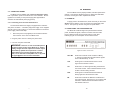
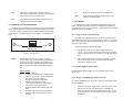
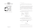
USER
MANUAL
MODEL 2112
100-User
Network Access Bridge
Part# 07M2112-A
Doc# 033081UA
Revised 06/22/99
CERTIFIED
An ISO-9001
Certified
Company
SALES OFFICE
(301)975-1000
TECHNICAL SUPPORT
(301)975-1007
http://www.patton.com
TABLE OF CONTENTS
SECTION
1.0 WARRANTY INFORMATION
PAGE
1.0 Warranty Information..............................................................2
1.1 Radio and TV Interference
1.2. CE Notice
1.3 Service
2.0 General Information ...............................................................4
2.1 Features
2.2 Description
2.3 Typical Application
3.0 Installation ..............................................................................6
3.1 Connecting the Twisted Pair Line Interface
3.2 Connecting the 10BaseT Ethernet Interface
3.3 Connecting Power
4.0 Operation .............................................................................10
4.1 Power- Up
4.2 Front Panel LED Status Monitors
4.3 Ethernet LED Status Monitors
4.4 Test Modes
Appendix A - Specifications ........................................................14
Appendix B - Factory Replacement Parts and Accessories .......15
Appendix C - Interface Pin Assignments ....................................16
Appendix D - Control Port Pin Assignment.................................37
Patton Electronics warrants all Model 2112 components to be
free from defects, and will—at our option—repair or replace the product should it fail within one year from the first date of shipment.
This warranty is limited to defects in workmanship or materials,
and does not cover customer damage, abuse or unauthorized modification. If this product fails or does not perform as warranted, your sole
recourse shall be repair or replacement as described above. Under no
condition shall Patton Electronics be liable for any damages incurred
by the use of this product. These damages include, but are not limited
to, the following: lost profits, lost savings and incidental or consequential damages arising from the use of or inability to use this product.
Patton Electronics specifically disclaims all other warranties,
expressed or implied, and the installation or use of this product shall
be deemed an acceptance of these terms by the user.
1.1 RADIO AND TV INTERFERENCE
The Model 2112 generates and uses radio frequency energy, and
if not installed and used properly—that is, in strict accordance with the
manufacturer's instructions—may cause interference to radio and television reception. The Model 2112 has been tested and found to comply with the limits for a Class A computing device in accordance with
the specifications in Subpart J of Part 15 of FCC rules, which are
designed to provide reasonable protection from such interference in a
commercial installation. However, there is no guarantee that interference will not occur in a particular installation. If the Model 2112 does
cause interference to radio or television reception, which can be determined by disconnecting the unit, the user is encouraged to try to correct the interference by one or more of the following measures: moving the computing equipment away from the receiver, re-orienting the
receiving antenna and/or plugging the receiving equipment into a different AC outlet (such that the computing equipment and receiver are on
different branches).
1.2 CE NOTICE
The CE symbol on your Patton Electronics equipment indicates
that it is in compliance with the Electromagnetic Compatibility (EMC)
directive and the Low Voltage Directive (LVD) of the European Union
(EU). A Certificate of Compliance is available by contacting Technical
Support.
1
2
2.0 GENERAL INFORMATION
1.3 SERVICE
All warranty and non-warranty repairs must be returned freight
prepaid and insured to Patton Electronics. All returns must have a
Return Materials Authorization number on the outside of the shipping
container. This number may be obtained from Patton Electronics
Technical Service at:
tel:
(301)975-1007
email: [email protected]
www: http://www.patton.com
Thank you for your purchase of this Patton Electronics product.
This product has been thoroughly inspected and tested and is warranted for One Year parts and labor. If any questions or problems arise
during installation or use of this product, please do not hesitate to contact Patton Electronics Technical Support at (301) 975-1000.
2.1 FEATURES
• Easy to Install -- No Configuration Required
• Full duplex bridging function over two wires
NOTE:
Packages received without an RMA number will
not be accepted.
• Provides MAC level connection between two peer Ethernet LANs
• Operates transparently to higher level protocols such as TCP/IP,
DECnet, NETBIOS and IPX
Patton Electronics' technical staff is also available to answer any
questions that might arise concerning the installation or use of your
Model 2112. Technical Service hours: 8AM to 5PM EST, Monday
through Friday.
• Automatically discovers, loads and deletes MAC addresses
• Point to Point distance of 3 Miles
• Loopback and pattern generator diagnostic
• LED indicators for TD, RD, CTS, CD, DTR, TM, ER and NS
WARNING!
This device is not intended to be connected to the public telephone network.
for line status
• LED indicators for status and link integrity for Ethernet port
• Made in the U.S.A.
2.2 DESCRIPTION
The Patton Electronics Model 2112-CO and 2112-CP 100-User
Ethernet LAN Bridge Extenders provide seamless LAN extension
between peered Ethernet LANs with all of the benefits of MAC level
bridging. You already own the twisted pair, why not use it to forward
Ethernet data to another Ethernet LAN -- up to 3.6 miles away!
Operating in pairs with a Model 2112-CO (looks like Central Office
equipment) on one end and a Model 2112-CP (looks like Customer
Premises equipment) on the other end, can automatically forward LAN
broadcasts, multi-casts and frames across the 2-Wire twisted pair link.
What’s more, the 2112s automatically add and delete MAC addresses,
only passing packets across the twisted pair that are meant for the
remote peered LAN. Higher level protocols such as TCP/IP, DECnet,
NETBIOS and IPX pass transparently through the Model 2112s without
modification.
3
4
3.0 INSTALLATION
2.3 TYPICAL APPLICATION
The 2112-CO and 2112-CP work together to create an extension
between 2 peer Ethernet LANs with all the benefits of MAC bridging.
The following diagram shows a typical application
The Model 2112 requires no configuration. You only need to connect the Ethernet interface, line interface between the units and power.
This section describes these connections.
Corporate Headquarters
Model 2112-CO
LAN
2-Wire Leased Line
10BaseT
Interface
Power IEC Power
Switch
Jack
Line
Interface
Figure 2. Model 2112 Rear Panel.
Ρεµοτε/Σατελλιτε Οφφιχε
3.1 CONNECTING THE TWISTED PAIR LINE INTERFACE
Model 2112-CP
LAN
Figure 1. Typical Application
The Model 2112 supports communication between two peer
Ethernet LAN sites at a distance up to 3.6 miles (5.8 km) over 24AWG
(.5mm) twisted pair wire. Follow the steps below to successfully connect the Model 2112 Line Interfaces.
1.
These units work in pairs. One unit in the pair must be a
Model 2112-CO (looks like Central Office equipment), and the
other unit must be a Model 2112-CP (looks like Customer
Premises equipment). It does not matter which end is the
2112-CO and which is the 2112-CP.
2. To function properly, the two Model 2112s must be connected
together using twisted pair metallic wire. This twisted pair
must be unconditioned, dry, metallic wire, between 19
(.9mm) and 26 AWG (.4mm). Standard dial-up telephone circuits, or leased circuits that run through signal equalization
equipment, or standard, flat modular telephone type cable,
are not acceptable.
5
6
3.
Observe the Signal/Pin relationships on the Model 2112’s Line
Interface jack. This Line Interface is a 2 wire interface.
1
2
3
4
5
6
7
8
1
2
3
4
5
6
7
8
3.2 CONNECTING THE 10BASET ETHERNET INTERFACE
The RJ-45 jack labeled “Interface Port” is the 10BaseT interface.
This port is designed to connect directly to a 10BaseT network. Figure
4, below, shows the Signal/Pin relationships on this interface. You may
connect this port to another Ethernet port via a Type 4 or Type 5 cable
that is up to 330 feet long.
(N/C)
(N/C)
(N/C)
(Tip)
(Ring)
(N/C)
(N/C)
(N/C)
1
2
3
4
5
6
7
8
Figure 3. Model 2112 twisted pair line interface.
4.
Connect the Line interface of a Model 2112-CO to the Line
interface of a Model 2112-CP with a twisted pair cable as
shown below:
1
2
3
4
5
6
7
8
TD+ (data output from 2112
TD- (data output from 2112)
RD+ (data input to 2112)
(no connection)
(no connection)
RD- (data input to 2112)
(no connection)
(no connection)
Figure 4. Line Interface.
3.2.1 Connecting the 10Base-T Ethernet Port to a Hub
SIGNAL
Tip
Ring
PIN
PIN
4 --------------------------4
5 --------------------------5
SIGNAL
Tip
Ring
NOTE: Any modular twisted pair cable connected to the
Model 2112 must be shielded cable, and the outer shield
must be properly terminated to a shielded modular plug on
both ends of the cable
The Model 2112 10Base-T interface is configured as DTE (Data
Terminal Equipment), just like a 10Base-T network interface card in a
PC. Therefore, it “expects” to connect to a 10Base-T Hub using a
straight-through RJ-45 cable. Use the diagram below to construct a
cable to connect the 2112 to a 10Base-T Hub.
2112
10Base-T Hub
RJ-45 Pin No.
RJ-45 Pin No.
1 (TX+) -------------------------------------------------1 (RX+)
2 (TX-) --------------------------------------------------2 (RX-)
3 (RX+)-------------------------------------------------3 (TX+)
6 (RX-)--------------------------------------------------6 (TX-)
3.2.2 Connecting the 10Base-T Ethernet Port to a PC (DTE)
The Model 21121 10Base-T interface is configured as DTE (Data
Terminal Equipment). If you wish to connect the 2112 to another DTE
device such as a 10Base-T network interface card in a PC, you must
construct a 10Base-T crossover cable as shown in the diagram below.
2112
RJ-45 Pin No.
1 (TX+)
2 (TX-)
3 (RX+)
6 (RX-)
7
10Base-T DTE
RJ-45 Pin No.
1 (TX+)
2 (TX-)
3 (RX+)
6 (RX-)
8
4.0 OPERATION
3.3 CONNECTING POWER
The Model 2112 is available with a Universal AC power supply
that is operable in power environments from 100 to 253VAC. No configuration is necessary for the power supply (See Appendix B for
domestic and international power plug options).
3.3.1 Connecting to an AC Power Power Source
The Universal Interface AC Supply is equipped with a male IEC320 power connection. A domestic (US) power supply cord is supplied
with the unit at no extra charge. To connect the standard or universwal
power supply, follow these steps:
1.
Attach the power cord (supplied) to the shrouded male IEC320 connector on the rear of the Model 2112.
Once the Model 2112 is properly installed, it should operate transparently. This sections describes power-up, reading the LED status
monitors, and using the built-in loopback test modes.
4.1 POWER-UP
To apply power to the Model 2112, first be sure that you have read
Section 3.3, and that the unit is connected to the appropriate power
source. Then power-up the unit using the rear power switch.
4.2 FRONT PANEL LED STATUS MONITORS
The Model 2112 features eight front panel LEDs that monitor
power, the Ethernet signals, network connection and test modes.
Figure 4 (below) shows the front panel location of each LED.
Following Figure 4 is a description of each LEDs function.
2. Plug the power cord into a nearby AC power outlet
3. Turn the rear power switch ON.
WARNING! There are no user-serviceable parts in
the power supply section of the Model 2112. Voltage
setting changes and fuse replacement should only be
performed by qulified service personnel. Contact
Patton Electronics Technical Support at (301)9751007, via our web-site at www.patton.com, or by email
at [email protected] for more information
9
Figure 4. Model 2112 Front Panel
TD & RD
Glows red to indicate an idle condition of Binary
“1” data on the respective terminal interface signals.
Green indicates Binary “0” data.
CTS
Glows green to indicate that the Clear to Send
signal from the modem is active.
CD
Glows red if no carrier signal is being received from
the remote modem. Green indicates that the remote
modem’s carrier is being received.
DTR
Glows green to indicate that the Data Terminal
Ready signal from the terminal is active.
ER
Glows red to indicate the likelihood of a Bit Error in
the received signal. During the 511 or 511/E test, ER
will flash to indicate that the Test Pattern Detector
has detected a bit error.
10
TM
NS
Glows red to indicate that the Model 2112 has
been placed in Test Mode. The unit can be placed in
test mode by the local or remote user.
Glow red to indicate that the local Model 2112 has
not yet connected with the remote.
4.3 ETHERNET LED STATUS MONITORS
The Model 2112 features two LEDs that monitor general operating
status and the 10Base-T twisted pair link integrity (located on the rear
of the unit). Figure 5 (below) shows the LEDs located directly beneath
the RJ-45 jack. Following Figure 5 is a description of each LEDs function.
11
Detected LAN receive frame(s) with bad CRC.
Link
Glows green to indicate good link integrity on the
10Base-T twisted pair line.
4.4 TEST MODES
The Model 2112 offers a proprietary loopback test mode, plus a
built-in V.52 BER test pattern generator, to evaluate the condition of
the modems and the communication link. These tests can be activated
physically from the front panel.
4.4.1 Using Local Line Loopback (LLB)
The Local Line Loopback (LLB) test checks the operation of the
local Model 2112, and is performed separately on each unit. Any data
sent to the local Model 2112 in this test mode will be echoed (returned)
back to the user device.
Quik-Connect Interface Module
Link LED
Status LED
To perform a LLB test, follow these steps:
Interface Port
1.
Activate LLB. Move the front panel toggle switch UP to
“Local”. Once LLB is activated, the Model 2112 transmitter
output is connected to its own receiver. The “TM” LED should
be lit.
2.
Verify that the data terminal equipment is operating properly
and can be used for a test. If a fault is indicated, call a
technician or replace the unit.
Figure 5. Model IM1/I Panel
Status
Blinks yellow from one to four times to indicate
system status. Each pulse pattern is separated by a
2 second “off” period. Greater pulse patterns have
higher priority (buffer saturation has greater priority
than an empty MAC table). Valid system statuses
are:
Pulses
1
2
3
4
5
6
7
8
9
10
Status
System status ok.
No MAC entries in the MAC address table.
Clear to send (CTS) or Carrier Detect (CD)
from base unit is not asserted.
Bridge module buffer is saturated.
WAN receive frame(s) too large.
WAN receive frame(s) not octet aligned.
WAN receive frames(s) aborted.
Detected WAN receive frame(s) with bad
CRC.
Detected LAN receive frame(s) too large.
Detected LAN receive frame(s) not octet
aligned.
11
4.4.2 Remote Digital Loopback (RDL)
Remote Digital Loopback (RDL) is not an available feature on the
Model 2112.
4.4.3 Using the V.52 (BER) Test Pattern Generator
To use the V.52 BER tests in conjunction with the loopback test follow
these instructions:
1.
Locate the “511/511E” toggle switch on the front panel of the
2112 and move it UP. This activates the V.52 BER test
mode and transmits a “511” test pattern into the loop. If any
errors are present, the local modem’s red “ER” LED will blink
sporadically.
12
APPENDIX A
2.
If the above test indicates no errors are present, move the
V.52 toggle switch DOWN, activating the “511/E” test with
errors present. If the test is working properly, the local
modem's red “ER” LED will glow. A successful “511/E” test
will confirm that the link is in place, and that the Model
2112’s built-in “511” generator and detector are working
properly.
13
PATTON ELECTRONICS MODEL 2112 SPECIFICATIONS
LAN Connection:
RJ-45, 10Base-T, IEEE 802.3 Ethernet
MAC Address Table Size:
4096 entries
MAC Address Aging:
MAC addresses deleted after 8 minutes
inactivity
On-board Memory:
512 KB RAM; 128 KB FLASH
Frame Latency:
1 frame
Transmission Line:
Two-Wire unconditioned twisted pair
Diagnostics:
V.52 compliant bit error rate pattern
(511/511E pattern) generator and detec
tor with error injection mode; Local Line
Loopback activated by front panel switch
LED Status Indicators:
TD, RD, CTS, CD, DTR, NS(no signal),
ER (error), TM (test mode) on front
panel; (1) general status; (1) link integri
ty on rear panel
Connectors:
RJ-45 on line side; RJ-45 on Ethernet
Port
Power:
100-253 VAC, 50-60 Hz (universal
input);
Temperature Range:
32-122°F (0° -50°C)
Altitude:
0-15,000 feet
Humidity:
5 to 95% non-condensing
Dimensions:
7.3” x 6.6” x 1.62” (185mm x 168mm x
41mm)
14
APPENDIX B
APPENDIX C
PATTON ELECTRONICS MODEL 2112 FACTORY REPLACEMENT
PARTS
AND ACCESSORIES
MODEL 2112 INTERFACE PIN ASSIGNMENT
Description
Patton Electronics Model #
0805US ...........................American Power Cord
0805EUR.........................European Power Cord CEE 7
0805UK ...........................United Kingdom Power Cord
0805AUS .........................Australia/New Zealand Power Cord
0805DEN.........................Denmark Power Cord
0805FR............................France/Belgium Power Cord
0805IN.............................India Power Cord
0805IS .............................Israel Power Cord
0805JAP..........................Japan Power Cord
0805SW...........................Switzerland Power Cord
15
10BASE-T Interface Pin Description
(RJ-45 Female Connector)
(DTE Configuration)
1
2
3
4
5
6
7
8
1 TD+ (data output from 2112)
2 TD- (data output from 2112)
3 RD+ (data input to 2112)
4 (no connection)
5 (no connection)
6 RD- (data input to 2112)
7 (no connection)
8 (no connection)
16
APPENDIX D
Dear Valued Customer,
MODEL 2112 INTERFACE PIN ASSIGNMENT
(continued)
Line Interface Pin Description
(RJ-45 Female Connector)
1
2
3
4
5
6
7
8
1
2
3
4
5
6
7
8
(N/C)
(N/C)
(N/C)
(Tip)
(Ring)
(N/C)
(N/C)
(N/C)
Figure 3. Model 2112 twisted pair line interface.
Thank you for purchasing Patton Electronics products! We
do appreciate your business. I trust that you find this user manual
helpful.
W e manufacture one of the widest selections of data communications products in the world including CSU/DSU’s, network termination units, powered and self-powered short range modems, fiber optic
modems, interface converters, baluns, electronic data switches, dataline surge protectors, multiplexers, transceivers, hubs, print servers
and much more. We produce these products at our Gaithersburg, MD,
USA, facility, and can custom manufacture products for your unique
needs.
W e would like to hear from you. Please contact us in any of
the following ways to tell us how you like this product and how we can
meet your product needs today and in the future.
W eb:
Sales E-mail:
Support E-mail:
Phone - Sales
Phone - Support
Fax:
Mail:
http://www.patton.com
[email protected]
[email protected]
(301) 975-1000
(301) 975-1007
(301) 869-9293
Patton Electronics Company
7622 Rickenbacker Drive
Gaithersburg, MD 20879 USA
W e are committed to a quality product at a quality price.
Patton Electronics is BABT and ISO 9001 certified. We meet and
exceed the highest standards in the industry (CE, UL, etc.).
It is our business to serve you. If you are not satisfied with
any aspect of this product or the service provided from Patton
Electronics or its distributors, please let m e know.
Thank you.
Burton A.Patton
Vice President
All Rights Reserved
17
P.S. Please tell us where you purchased this product.
________________________________________________________
________________________________________________________
________________________________________________________
________________________________________________________
________________________________________________________