1
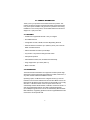
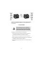
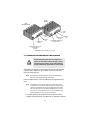
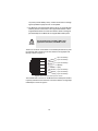
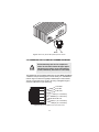
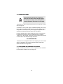
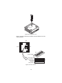
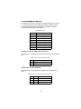
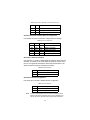
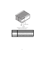
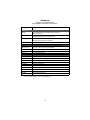
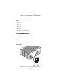
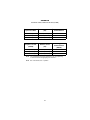
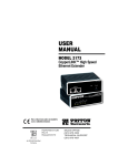
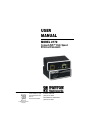
USER
MANUAL
MODEL 2172
CopperLINK™ High Speed
Ethernet Extenders
Part# 07M2172-UM
Doc# 03333U2-001
Rev. A
Revised 10/24/06
An ISO-9001Certified
Company
SALES OFFICE
(301) 975-1000
TECHNICAL SUPPORT
(301) 975-1007
CONTENTS
1.0
1.1
1.2
1.3
1.4
1.5
Warranty Information .................................................................
Compliance...................................................................................
EMC Compliance:.........................................................................
Safety Compliance: ......................................................................
Radio and TV Interference (FCC Part 15) ....................................
Declaration of Conformity .............................................................
Service..........................................................................................
Safety When Working With Electricity ..........................................
4
4
4
4
4
5
5
6
2.0
2.1
2.2
General Information.................................................................... 7
Features........................................................................................ 7
Description.................................................................................... 7
3.0
3.1
3.2
3.3
Installation................................................................................... 8
Connecting the Twisted-Pair Line Interface.................................. 9
Connecting the 10/100Base-T Ethernet Interface ...................... 11
Connecting Power ...................................................................... 12
4.0
4.1
4.2
Configuration ............................................................................
Configuring the hardware DIP switches......................................
Configuring DIP Switch S2 .........................................................
Switch S2-1: Symmetric/Asymmetric Operation.........................
Switches S2-2 and S2-3: Data Rate...........................................
5.0
5.1
5.2
Operation................................................................................... 16
Power Up .................................................................................... 16
Front Panel LED Status Monitors ............................................... 16
12
12
14
14
14
A
A.1
A.2
A.3
A.4
A.5
A.6
A.7
A.8
A.9
Specifications ........................................................................... 18
LAN Connection .......................................................................... 18
Transmission Line ....................................................................... 18
CopperLINK Line Rate and CopperLINK Distance .................... 18
CopperLINK Surge Suppressor .................................................. 18
LED Status Indicators ................................................................. 18
Power Supply .............................................................................. 18
Temperature Range .................................................................... 18
Humidity ...................................................................................... 18
Dimensions ................................................................................. 18
B
Model 2172 Series Factory
Replacement Parts and Accessories...................................... 19
C
Model 2172 Series Interface Pin Assignment ........................ 20
2
C.1 10/100Base-T Interface .............................................................. 20
RJ-45 .......................................................................................... 20
C.2 CopperLINK Interface ................................................................. 20
RJ-45 .......................................................................................... 20
Terminal Block............................................................................ 20
D
Distance Chart, Based on 24 AWG (0.5 MM) .......................... 21
3
1.0 WARRANTY INFORMATION
Patton Electronics warrants all Model 2172 components to be free from
defects, and will—at our option—repair or replace the product should it
fail within one year from the first date of the shipment.
This warranty is limited to defects in workmanship or materials, and does
not cover customer damage, abuse or unauthorized modification. If this
product fails or does not performs as warranted, your sole recourse shall
be repair or replacement as described above. Under no condition shall
Patton Electronics be liable for any damages incurred by the use of this
product. These damages include, but are not limited to, the following: lost
profits, lost savings and incidental or consequential damages arising
from the use of or inability to use this product. Patton Electronics specifically disclaims all other warranties, expressed or implied, and the
installation or use of this product shall be deemed an acceptance of
these terms by the user.
Note
Conformity documents of all Patton products can be viewed
online at www.patton.com under the appropriate product page.
1.1 COMPLIANCE
EMC Compliance:
• FCC Part 15, Class A
• EN55022, Class A
• EN55024
Safety Compliance:
• IEC/EN 60950-1
• AS/NZS 60950-1
1.2 RADIO AND TV INTERFERENCE (FCC PART 15)
This equipment generates and uses radio frequency energy, and if not
installed and used properly—that is, in strict accordance with the manufacturer's instructions—may cause interference to radio and television
reception. This equipment has been tested and found to comply with the
limits for a Class A computing device in accordance with the specifications in Subpart B of Part 15 of FCC rules, which are designed to provide
reasonable protection from such interference in a commercial installation. However, there is no guarantee that interference will not occur in a
particular installation. If the equipment causes interference to radio or
4
television reception, which can be determined by disconnecting the
cables, try to correct the interference by one or more of the following
measures: moving the computing equipment away from the receiver, reorienting the receiving antenna, and/or plugging the receiving equipment
into a different AC outlet (such that the computing equipment and
receiver are on different branches).
1.3 DECLARATION OF CONFORMITY
We certify that the apparatus identified in this document conforms to the
requirements of Council Directive 1999/5/EC on the approximation of the
laws of the member states relating to Radio and Telecommunication Terminal Equipment and the mutual recognition of their conformity.
The safety advice in the documentation accompanying this product shall
be obeyed. The conformity to the above directive is indicated by the CE
sign on the device.
1.4 SERVICE
All warranty and non-warranty repairs must be returned freight prepaid
and insured to Patton Electronics. All returns must have a Return Materials Authorization number on the outside of the shipping container. This
number may be obtained from Patton Electronics Technical Services at:
• Tel: +1 (301) 975-1007
• Email: [email protected]
• URL: http://www.patton.com
Note
Packages received without an RMA number will not be
accepted.
5
1.5 SAFETY WHEN WORKING WITH ELECTRICITY
• This device contains no user serviceable parts. The
equipment shall be returned to Patton Electronics for
repairs, or repaired by qualified service personnel.
• Mains Voltage: Ensure that the external power adapter
is a listed Limited Power Source. The mains outlet that
is utilized to power the devise shall be within 10 feet (3
meters) of the device, shall be easily accessible, and
protected by a circuit breaker. Ensure that the power
cable used meets all applicable standards for the country in which it is to be installed, and that it is connected
to a wall outlet which has earth ground.
WARNING
• Hazardous network voltages are present in WAN ports
regardless of whether power to the unit is ON or OFF. To
avoid electric shock, use caution when near WAN ports.
When detaching the cables, detach the end away from
the device first.
• Do not work on the system or connect or disconnect
cables during periods of lightning activity.
In accordance with the requirements of council directive 2002/96/EC on Waste of Electrical and Electronic
Equipment (WEEE), ensure that at end-of-life you separate this product from other waste and scrap and deliver
to the WEEE collection system in your country for recycling.
6
2.0 GENERAL INFORMATION
Thank you for your purchase of this Patton Electronics product. This
product has been thoroughly inspected and tested and is warranted for
one year for parts and labor. If any questions or problems arise during
installation or use of this product, contact Patton Electronics Technical
Support at +1 (301) 975-1007.
2.1 FEATURES
• Variable rate CopperLINK extender - Easy to configure
• Auto-MDIX Ethernet
• Configurable 10/100, Full/Half, and Auto-Negotiating Ethernet
• Extends network connections up to 6,000 ft (1.8 km) over 2-wire 24AWG unconditioned lines
• Switch selectable line rates up to 50 Mbps
• 6 symmetric or asymmetric settings via DIP switch
• Transparent operation
• LED indicators for Power, Link, and Ethernet Link & Activity
• Surge suppression up to 20 kA (8/20 µs)
• Made in the USA
2.2 DESCRIPTION
The Patton Electronics Model 2172 CopperLink modems provide highspeed LAN connections between peered Ethernet LANs, remote PC’s, or
any other network enabled 10/100Base-T device.
Operating in pairs, one Model 2172 is configured as the (L) Local unit
located at one end of the LAN extension and the other Model 2172 is configured as the (R) Remote unit at the other end. The Model 2172 is configured as a L or R via the switch on the rear panel. These units can
automatically forward LAN broadcasts, multicasts, and frames across a 2wire voice-grade twisted-pair link. The data is passed transparently
(unmodified) through the 2172s. The 2172s automatically add and delete
MAC addresses, only passing packets across the CopperLINK link that are
meant for the remote peered LAN.
7
Figure 1. Typical application
The pair of 2172 models work together to create a transparent extension
between two peered Ethernet LANs. Figure 1 shows a typical point-topoint application.
3.0 INSTALLATION
CAUTION
The Interconnecting cables shall be acceptable for
external use and shall be rated for the proper application with respect to voltage, current, anticipated temperature, flammability, and mechanical serviceability.
To install the 2172 Ethernet Extender, do the following:
1. Connect the line interface between the units (refer to section 3.1,
“Connecting the Twisted-Pair Line Interface” on page 9)
Note
See Figure 2 for the standalone unit’s rear panel arrangements.
2. Connect the Ethernet interface (refer to section 3.2, “Connecting the
10/100Base-T Ethernet Interface” on page 11).
3. Connect the power plug (refer to section 3.3, “Connecting Power” on
page 12).
8
2172
(RJ-45)
2172
(Terminal block)
A
e in
the
US
Mad
A
e in
the
et
US
er
t
ne
r
we
Po
ern
Eth
Mad
c
r
we
Po
Power
jack
Lo
m
e
Eth
Re
Lin
c
Lo
m
Re
Local/Remote
switch
Power
jack
Ethernet
port
Local/Remote
switch
Ethernet
port
CopperLINK twisted-pair
RJ-45 interface
CopperLINK twisted-pair
terminal block
interface
Figure 2. Model 2172 standalone rear panel
3.1 CONNECTING THE TWISTED-PAIR LINE INTERFACE
CAUTION
The Interconnecting cables shall be acceptable for
external use and shall be rated for the proper application with respect to voltage, current, anticipated temperature, flammability, and mechanical serviceability.
The Model 2172 supports communication between two peer Ethernet
LAN sites over a distance of up to 6,000 ft (1.8 km) over 24 AWG
(0.5 mm) twisted-pair wire.
Note
Actual distance and link performance may vary depending on
the environment and type/gauge of wire used.
Follow the steps below to connect the Model 2172 CopperLINK Interfaces.
Note
The Model 2172 units work in pairs. One of the units must be
configured as a (L) Local unit, and the other unit must be configured as a (R) Remote unit. It does not matter which end is the L
and which is the R. The link is always initiated by the R unit. As
long as the L unit is powered on, the R unit can establish a link
by being powered on or by having its power reset.
1. To function properly, the two Model 2172s must be connected
together using twisted-pair, unconditioned, dry, metal wire, between
9
19 (0.9mm) and 26 AWG (0.4mm). Leased circuits that run through
signal equalization equipment are not acceptable.
2. The Model 2172 is equipped with either an RJ-45 or a terminal block
interface jack that can be used on the CopperLINK interface. These
CopperLINK interfaces are a two-wire interface. Observe the signal/
pin relationships on the Model 2172's CopperLINK interface jacks.
The Line port has been classified as TNV-1 and is
approved for connection to a PSTN TNV-1 circuit.
WARNING
The RJ-45 connector on the Model 2172's twisted pair interface is polarity insensitive and is wired for a two-wire interface. The signal/pin relationship is shown in Figure 3.
1 (no connection)
2 (no connection)
1
2
3
4
5
6
7
8
3 (no connection)
4 (RING)
5 (TIP)
6 (no connection)
7 (no connection)
8 (no connection)
Figure 3. Model 2172 (RJ-45) twisted pair line interface.
The terminal block connector on the Model 2172's twisted pair interface
is polarity insensitive and is wired for a two-wire interface. The signal/pin
relationships is shown in Figure 4.
10
A
de
in
the
US
Ma
r
the
t
ne
r
we
Po
E
c
Lo
m
Re
RING
TIP
Figure 4. Model 2172 (Terminal Block) twisted pair line interface.
3.2 CONNECTING THE 10/100BASE-T ETHERNET INTERFACE
CAUTION
The Interconnecting cables shall be acceptable for
external use and shall be rated for the proper application with respect to voltage, current, anticipated temperature, flammability, and mechanical serviceability.
The shielded RJ-45 port labeled Ethernet is the Auto-MDIX10/100BaseT interface. This port is designed to connect directly to a 10/100Base-T
network. Figure 5 shows the signal/pin relationships on this interface.
You may connect this port to a hub or PC using a straight through or
crossover cable that is up to 328 ft long.
1 TX+/RX+
2 TX-/RX-
1
2
3
4
5
6
7
8
3 RX+/TX+
4 (no connection)
5 (no connection)
6 RX-/TX7 (no connection)
8 (no connection)
Figure 5. Model 2172 10/100Base-T RJ-45 Connector Pinout.
11
3.3 CONNECTING POWER
CAUTION
The Interconnecting cables shall be acceptable for
external use and shall be rated for the proper application with respect to voltage, current, anticipated temperature, flammability, and mechanical serviceability.
The Model 2172 does not have a power switch, so it powers up as soon
as it is plugged in.
An external AC or DC power supply is available separately. This connection is made via the barrel jack on the rear panel of the Model 2172. No
configuration is necessary for the power supply (See Appendix B for
domestic and international power supply and cord options).
DC power (supplied via the power supply jack to the 2172) must meet
the following requirements; DC power supplied must be regulated
+5VDC ±5%, 1.0A minimum. Center pin is +5V. The barrel type plug has
a 2.5/5.5/10mm I.D./O.D./Shaft Length dimensions.
4.0 CONFIGURATION
The Model 2172 has eight DIP switches for configuring the unit for a wide
variety of applications. This section describes switch locations and
explains the different configurations.
4.1 CONFIGURING THE HARDWARE DIP SWITCHES
Using a small flat-tip screwdriver, remove the protective cover located on
the underside of the Model 2172 (see Figure 6).
12
er
Pow
net
Eth
er
Link
Hig
hS
pe
ed
Eth
™
INK
erL der
pp
n
Co Exte
et
ern
Figure 6. Removing protective cover
Figure 7 on page 13 shows the orientation of the DIP switches in the On
and Off positions.
S2
ON
S2
1 2 3 4 5 6 7 8
Rear
N
4
3
1
2
Switch toggle
5
6
7
8
S2
O
Front
Push toggle
down for
OFF position
1 2 3 4 5 6 7 8
Figure 7. DIP switch orientation
13
S2
Push toggle up ON
for ON position
4.2 CONFIGURING DIP SWITCH S2
DIP switch S2 is where you configure the CopperLINK line rate, symmetric or asymmetric, Ethernet, and Ethernet Shutdown. Table 1 summarizes default positions of DIP switches S2-1 through S2-8. Detailed
descriptions of each switch follow the table.
Table 1: S2 Summary
Position
S2-1
S2-2
S2-3
S2-4
S2-5
S2-6
S2-7
S2-8
Description
Symmetric/Asymmetric
Line Rate
Line Rate
Ethernet configuration
Ethernet configuration
Ethernet configuration
Ethernet Shutdown
Remote Configuration
Switch S2-1: Symmetric/Asymmetric Operation
Use switch S2-1 to configure the unit for symmetric or asymmetric operation..
Table 2: Ethernet Auto Sense Selection Chart
S2-1
ON
OFF
Setting
Symmetric Operation
Asymmetric Operation
Switches S2-2 and S2-3: Data Rate
Use switches S2-1, S2-2 and S2-3 to configure the CopperLINK line
rates.
Table 3: Symmetric CopperLINK Line Rates Selection Chart
S2-2
S2-3
Symmetric Line Rate
OFF
ON
OFF
ON
OFF
OFF
50 Mbps
25 Mbps
10 Mbps
14
Table 4: Asymmetric CopperLINK Line Rates Selection Chart
S2-2
S2-3
Asymmetric Line Rates DS/US
ON
ON
OFF
ON
OFF
OFF
50 Mbps/2 Mbps
16 Mbps/2 Mbps
4 Mbps/1 Mbps
Switches S2-4, S2-5 and S2-6: Ethernet Configuration
Use switches S2-4, S2-5 and S2-6 to configure Ethernet settings.
Table 5: Ethernet configurations
S2-4
S2-5
S2-6
Ethernet Configurations
ON
ON
ON
ON
OFF
ON
ON
OFF
OFF
ON
ON
OFF
ON
OFF
ON
Auto-Negotiate
100Mb Full Duplex
100Mb Half Duplex
10Mb Full Duplex
10Mb Half Duplex
Switch S2-7: Ethernet Shutdown
Use switch S2-7 to enable or disable Ethernet Shutdown. When Ethernet
Shutdown is enabled, the 2172 will disable the Ethernet interface when
there is no CopperLINK link detected. When Ethernet Shutdown is disabled, the Ethernet interface will always be enabled.
Table 6: Ethernet Shutdown
S2-7
ON
OFF
Description
Ethernet Shutdown Enabled
Ethernet Shutdown Disabled
Switch S2-8: Remote Configuration
Use switch S2-8 to enable or disable Remote Configuration.
Table 7: Ethernet Shutdown
Note
S2-8
Description
ON
OFF
Remote Configuration Enabled
Remote Configuration Disabled
The S2-8 switch applies to the R unit only. If enabled, the R will
follow the dip switch configuration of the L unit. If disabled, the R
unit will use its own dip switch setting to determine its Ethernet
15
operating mode and Ethernet Shutdown mode configuration.
The S2-8 switch does not affect the data rate. The data rate will
always follow the L configuration.
5.0 OPERATION
Once the Model 2172s are properly installed, they should operate transparently. No user settings required. This section describes reading the
LED status monitors.
5.1 POWER UP
Before applying power to the Model 2172, please review section 3.3,
“Connecting Power” on page 12 to verify that the unit is connected to the
appropriate power source.
5.2 FRONT PANEL LED STATUS MONITORS
The Model 2172 features three front panel LEDs that monitor power, the
Ethernet signals, and the CopperLINK connection. Figure 8 shows the
front panel location of each LED. Table 8 on page 17 describes the LED
functions.
16
INK
erL er
pp
d
Co xten
E
et
n
r
e
ed
pe
hS
Eth
Pow
er
Link
Ether
net
Hig
Power
LED
Ethernet LED
Link LED
Figure 8. Model 2172 standalone unit front panel
Table 8: Front panel LED description
LED
PWR
LINK
ETH
Description
Solid GREEN to indicate the unit is powered on.
Solid GREEN (ON) to indicate that the end-to-end
CopperLINK link between the Model 2172s is established. The Link LED is OFF when the link is down.
Solid GREEN indicates that 10/100Base-T Ethernet
link has been established. Flashes to indicate activity.
17
APPENDIX A
SPECIFICATIONS
A.1 LAN CONNECTION
• Shielded RJ-45, 10/100Base-T, IEEE 802.3 Ethernet
• CopperLINK Connection: RJ-45 or Terminal Block
A.2 TRANSMISSION LINE
Two-wire unconditioned twisted pair.
A.3 COPPERLINK LINE RATE AND COPPERLINK DISTANCE
• Line Rate: 50 Mbps, symmetric upstream/downstream. Additional
symmetric and asymmetric rates are available via DIP switch settings.
• Distance: 6,000 ft (1.8 km) at 1 Mbps upstream/4 Mbps downstream
Note
Distances depend on selected line rate and line conditions. See
Appendix D on page 21 for details.
A.4 COPPERLINK SURGE SUPPRESSOR
SIDACTOR with maximum current surge: 20 kA (8/20 µs).
A.5 LED STATUS INDICATORS
• Power (Green)
• CopperLINK: Link (Green)
• Ethernet: Link (Green) & Activity (Flashing Green)
A.6 POWER SUPPLY
External AC and DC options:
• AC: 120 VAC, 220 VAC, and UI (120–240 VAC)
• DC: 12 VDC, 24 VDC and 48 VDC
• Power consumption: 450 mA at 5 VDC
A.7 TEMPERATURE RANGE
0–50°C
A.8 HUMIDITY
Up to 90% non-condensing.
A.9 DIMENSIONS
1.58H x 4.16W x 3.75D in. (10.6H x 4.1W x 8.8D cm)
18
APPENDIX B
MODEL 2172 SERIES FACTORY
REPLACEMENT PARTS AND ACCESSORIES
Patton Model #
Description
Base Models
2172/E
2172/E-2PK
2172/EUI-2PK
07M2172-UM
CopperLINK Multi Rate 50 Mbps Ethernet Extender;
No power supply
CopperLINK Multi Rate 50 Mbps Ethernet Extender Kit (2 units preset to local and remote); No power supply
CopperLINK Multi Rate 50 Mbps Ethernet Extender Kit (2 units preset to local and remote); 110-240VAC
User Manual
Power Supplies
08055DCUI
08055-120-5-1
12V-PSM
24V-PSM
48V-PSM
100-240VAC (+5V reg. DC/2A) Universal Input Adapter.
120 VAC (+5V reg. DC/1A) Input Adapter
12 VDC Input Adapter
24 VDC Input Adapter
48 VDC Input Adapter
Power Cords*
0805US
0805EUR
0805UK
0805AUS
0805DEN
0805FR
0805IN
0805IS
0805JAP
0805SW
American Power Cord
European Power Cord CEE 7
United Kingdom Power Cord
Australian Power Cord
Denmark Power Cord
France/Belgium Power Cord
India Power Cord
Israel Power Cord
Japan Power Cord
Switzerland Power Cord
*Only required with optional UI power supply (08055DCUI)
19
APPENDIX C
MODEL 2172 SERIES INTERFACE PIN ASSIGNMENT
C.1 10/100BASE-T INTERFACE
RJ-45
• Pin 1: TX+
• Pin 2: TX• Pin 3: RX+
• Pin 6: RX• Pins 4, 5, 7, 8: no connection
C.2 COPPERLINK INTERFACE
RJ-45
• Pin 4: RING
• Pin 5: TIP
• Pins 1, 2, 3, 6, 7, 8: no connection
Terminal Block
A
de
in
the
US
Ma
et
rn
he
Et
r
we
Po
c
Lo
m
Re
RING
TIP
Figure 1. Model 2172 (Terminal Block) twisted pair line interface..
20
APPENDIX D
DISTANCE CHART, BASED ON 24 AWG (0.5 MM)
Symm Line Rate
Distance in feet
(km)
Throughput
at Max Distance
50 Mbps
25 Mbps
10 Mbps
800 (0.25 km)
2,000 (0.61 km)
4,000 (1.22 km)
48
24.5
10
Asymm Line Rate
(DS/US)
Distance in feet
(km)
Throughput
at Max Distance
(DS/US)
50 Mbps/2 Mbps
16 Mbps/2 Mbps
4 Mbps/1 Mbps
2,000 (0.61 km)
4,000 (1.22 km)
6,000 (1.82 km)
48/2
15/2
3.75/1
Note
The actual distance and link performance may vary depending
on the environment and type/gauge of wire used.
Note
DS = downstream, US = upstream
21
Copyright © 2001, 2002, 2006
Patton Electronics Company
All Rights Reserved.
22