1
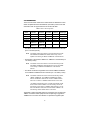
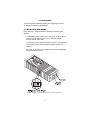
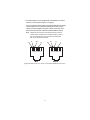
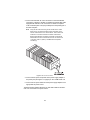
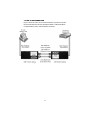
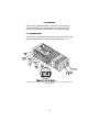
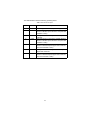
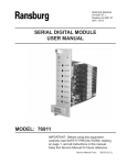
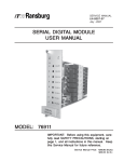
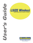
USER
MANUAL
MODEL 1170M SERIES
Ethernet Fiber Modems
(1170M, 1171M, 1172M)
Part# 07M1170M
Doc# 077351U Rev. A
Revised 4/14/03
An ISO-9001
Certified Company
SALES OFFICE
(301) 975-1000
TECHNICAL SUPPORT
(301) 975-1007
CONTENTS
1.0
1.1
1.2
1.3
Warranty Information .................................................................
Radio and TV Interference............................................................
CE Notice......................................................................................
Service..........................................................................................
2.0
2.1
2.2
General Information.................................................................... 5
Features........................................................................................ 5
Description.................................................................................... 6
3.0
3.1
3.2
Installation................................................................................... 8
Installing a Fiber Modem .............................................................. 8
End-to-end connection................................................................ 11
4.0
4.1
Operation................................................................................... 12
LED indicators ............................................................................ 12
A
A.1
A.2
A.3
A.4
A.5
1.6
A.7
Specifications ........................................................................... 14
Interfaces/Connectors ................................................................ 14
Interface Speed .......................................................................... 14
Transmission Mode ..................................................................... 14
Twisted-Pair/Copper Cable Type* .............................................. 14
Fiber Cable Type ........................................................................ 14
Fiber Wavelength........................................................................ 14
Fiber Optic Link Budget .............................................................. 15
Transmit power........................................................................... 15
Receiver Sensitivity .................................................................... 15
Delay Time ................................................................................. 15
Typical Fiber Max. Distance ....................................................... 15
Standards ................................................................................... 15
LED Status Indicators ................................................................. 15
Compliance ................................................................................. 16
Power .......................................................................................... 16
Packaged Weight ....................................................................... 16
Dimensions ................................................................................. 16
Environment ................................................................................ 16
A.8
A.9
A.10
A.11
A.12
A.13
A.14
2
3
3
3
4
1.0 WARRANTY INFORMATION
Patton Electronics warrants all Model 1170M Series components to be
free from defects, and will—at our option—repair or replace the product
should it fail within one year from the first date of shipment.
This warranty is limited to defects in workmanship or materials, and does
not cover customer damage, abuse, or unauthorized modification. If this
product fails or does not perform as warranted, your sole recourse shall
be repair or replacement as described above. Under no condition shall
Patton Electronics be liable for any damages incurred by the use of this
product. These damages include, but are not limited to, the following: lost
profits, lost savings and incidental or consequential damages arising
from the use of or inability to use this product. Patton Electronics specifically disclaims all other warranties, expressed or implied, and the
installation or use of this product shall be deemed an acceptance of
these terms by the user.
1.1 RADIO AND TV INTERFERENCE
The Model 1170M Series generates and uses radio frequency energy,
and if not installed and used properly—that is, in strict accordance with
the manufacturer's instructions—may cause interference to radio and
television reception. The Model 1170M Series has been tested and
found to comply with the limits for a Class A computing device in accordance with the specifications in Subpart B of Part 15 of FCC rules, which
are designed to provide reasonable protection from such interference in
a commercial installation. However, there is no guarantee that interference will not occur in a particular installation. If a 1170M Series unit does
cause interference to radio or television reception, which can be determined by disconnecting the cables, the user is encouraged to try to correct the interference by one or more of the following measures: moving
the computing equipment away from the receiver, re-orienting the receiving antenna, and/or plugging the receiving equipment into a different AC
outlet (such that the computing equipment and receiver are on different
branches).
1.2 CE NOTICE
The CE symbol on your Patton Electronics equipment indicates that it is
in compliance with the Electromagnetic Compatibility (EMC) directive
3
and the Low Voltage Directive (LVD) of the Union European (EU). A Certificate of Compliance is available by contacting Technical Support.
This device is not intended to be connected to the public
telephone network.
Caution
1.3 SERVICE
All warranty and nonwarranty repairs must be returned freight prepaid
and insured to Patton Electronics. All returns must have a Return Materials Authorization number on the outside of the shipping container. This
number may be obtained from Patton Electronics Technical Services at:
• Tel: +1 (301) 975-1007
• Email: [email protected]
• URL: http://www.patton.com
Note
Packages received without an RMA number will not be
accepted.
4
2.0 GENERAL INFORMATION
Thank you for your purchase of this Patton Electronics product. It has
been thoroughly inspected and tested and is warranted for one year for
parts and labor. If you have any questions about this product, please call
Patton Electronics Technical Support at (301) 975-1007.
2.1 FEATURES
• Cost effective plug and play solution for extending your 10Base-T and
100Base-TX using 10Base-FL, 100Base-FX, and 100Base-SX fiber
• Supports 802.3 and 802.3u, 10Base-T, 10Base-FL, 100Base-TX,
100Base-FX, and 100Base-SX industry standards
• Extends network connections up to 2 km (1.24 miles) over multi-mode
fiber media.
• Low power consumption
• Auto-sensing full or half duplex Ethernet operation
• Twisted Pair MDI/MDI-X switch
• ST or SC connectors for connecting to multimode fiber media
• Ultra-miniature MicroPak Chassis
• LED indicators for Power, Fiber Link and Activity, and Twisted-pair Link
and Activity
• External power supply adapter with AC and DC options
5
2.2 DESCRIPTION
There are three base models in the Patton Model 1170M Series of standards compliant Ethernet Fiber Modems (see Table 1) that convert and
extend the reach of copper Ethernet over multi-mode fiber.
Table 1: Model 1170M configurations
Model
Twisted-Pair
Standard
Fiber
Standard
Connector
Distance
Wavelength
1170M-ST
100Base-TX
100Base-FX
ST
2 km
1300nm
1170M-SC
100Base-TX
100Base-FX
SC
2 km
1300 nm
1171M-ST
10Base-T
10Base-FL
ST
2 km
850nm
1171M-SC
10Base-T
10Base-FL
SC
2 km
850nm
1172M-ST
10Base-T/
100Base-TX
10Base-FL/
100Base-FX
ST
2 km
1300nm
1172M-SC
10Base-T/
100Base-TX
10Base-FL/
100Base-FX
SC
2 km
1300nm
• The Model 1170M converts 100Base-TX to 100Base-FX and extends
up to 1.24 miles (2.0 km).
Note
The Model 1172M can be used to connect auto-sensing 10/100
and 100Base-TX/100Base-FX network devices only; it is not
capable of connecting to 10Base-T/10Base-FL network devices.
• The Model 1171M converts 10Base-T to 10Base-FL and extends up to
1.24 miles (2.0 km).
Note
The Model 1171M can be used to connect auto-sensing 10/100
and 10Base-T/10Base-FL network devices only; it is not capable
of connecting to 100Base-TX/100Base-FX or SX network
devices.
• The Model 1172M auto-negotiates and converts 10Base-T/100BaseTX to 10Base-FL/100Base-FX and extends up to 1.24 miles (2.0 km).
Note
The Model 1172M can be used to connect auto-sensing 10/100,
10Base-T/10Base-FL, and 100Base-T/100Base-FX network
devices. The Model 1172M cannot connect a 10Base network
device on one side to a 100Base network device on the other.
If a 10Base network device is on one side of the Model 1172M,
there must be another 10Base or an auto-sensing 10/100 network device on the other. If a 100Base network device is on one
side of the Model 1172M, there must be another 100Base or an
auto-sensing 10/100 network device on the other.
The Model 1172M is the ideal product for customers who currently have
10Base-T networks and/or equipment and are planning to upgrade to
100Base-TX in the future. The Model 1172 provides a migration path
6
from 10Base-T/10Base-FL to 100Base-TX/100Base-FX, which eliminates the need to upgrade and lowers the overall cost of ownership.
All Patton 1170M Series models are packaged in an ultra-miniature
MicroPak chassis and feature power, fiber link and activity, and twistedpair link and activity LED indicators. The Model 1170M Series of Ethernet Fiber Modems can be ordered with ST or SC fiber optic connectors
and with 120VAC, 220VAC, universal interface (UI), -48 VDC, -24 VDC,
or -12 VDC power supply adapters. Power cord designations for
220 VAC and UI models must be specified at the time of purchase.
7
3.0 INSTALLATION
The following sections describe installing and configuring the Model
1170M Series of Ethernet Fiber Modems
3.1 INSTALLING A FIBER MODEM
Do the following to install the Model 1170M Series of Ethernet Fiber
Modems:
1. The MDI/MDI-X switch enables you to connect the 1170M models to
different types of network devices using a standard (straightthrough) network patch cable.
To connect the 1170M models to a terminal, transceiver, or network interface card (NIC), set the switch to the MDI-X (lefthand) position (see
Figure 1).
Otherwise, to connect to a hub or switch, set the switch to the MDI (righthand) position (see Figure 1).
Figure 1. MDI/MDI-X switch, Ethernet RJ-45 jack, and power jack locations
8
2. The Fiber Modem comes equipped with a shielded RJ-45 Jack for
Ethernet connections (see Figure 1 on page 8).
Connect the Ethernet RJ-45 jack to the appropriate 802.3 compliant
network equipment via a standard network patch cable (not provided). The pinout diagrams in Figure 2 reflect the pinouts of the
Ethernet RJ-45 jack when switched to MDI and MDI-X settings.
Note
T+
Twisted-pair connections from the Ethernet RJ-45 Jack to the
network device should be 802.3 compliant (Category 5 STP or
UTP recommended) and must not exceed 100 meters (328
feet). Do not use flat or satin cable.
T+
R+
R-
R+
R+
T+
T-
12345678
12345678
MDI
MDI-X
Figure 2. Shielded Ethernet RJ-45 Jack pin-outs with different MDI/MDI-X switch settings
9
3. Connect the dual fiber ST or SC connectors on the Fiber Modem
(see Figure 3) directly to the 802.3 compliant multi-mode fiber cable
equipped with male ST or SC connectors or via 802.3 compliant
multi-mode fiber patch cord (not provided) and corresponding ST or
SC fiber wall jacks.
Note
Verify that the cable connecting the TX and RX of the 1170M
Series unit is connected to the RX and TX respectively on the
remote 1170M Series unit or network device. End-to-end multimode fiber connections between two Model 1170M Series
Ethernet Fiber Modems or between one Model 1170M Series
Fiber Modem and other network devices must not exceed 2 km
(1.24 miles), 298.7 m (980 ft) in 100Base-SX mode (Model
1172M only).
Figure 3. Fiber connector locations
4. Connect the DC power output side of the power supply adapter to
the power jack (see Figure 1 on page 8) on the 1170M Series unit.
5. Connect the AC power side/cord of the power supply adapter to the
appropriate AC power source.
The Ethernet Fiber Modem will power up and LED indicators will illuminate once connected to the power source.
10
3.2 END-TO-END CONNECTION
Figure 4 shows an end-to-end connection between a personal computer/
terminal and Ethernet hub using two Patton Model 1170M Series Ethernet Fiber Modems and a multi-mode fiber connection.
Figure 4. End-to-end multi-mode fiber connection
11
4.0 OPERATION
Once you have installed the Model 1170M Series unit and have connected the External Power Supply Adapter to the appropriate power
source, the unit will power up automatically and is ready to operate.
4.1 LED INDICATORS
Once powered up, LED indicators located on the side of the Model 1170M
Series unit will illuminate to indicate the operating status of the unit.
Figure 5. Location of 1170M Series LED indicators (Move fiber connectors to the opposite
end of the modem)
12
The LED indicators reflect the following operating status:
Table 2: LED indicator descriptions
Number
Name
Description
1
2
PWR
FO100
3
FOACT
4
FO10
5
TP100
6
TPACT
7
TP10
Illuminates green to shown that power is applied to unit.
Illuminates green to show that a 100 Mbps signal is
present on the fiber optic side of the unit. (Not used
on Model 1171M.)
Blinks yellow to show activity on the fiber optic side
of the unit.
Illuminates green to show that a 10 Mbps signal is
present on the fiber optic side of the unit. (Not used
on Model 1170M.)
Illuminates green to show that a 100 Mbps signal is
present on the twisted-pair/copper side of the unit.
(Not used on Model 1171M.)
Blinks yellow to show activity on the twisted-pair/
copper side of the unit.
Illuminates green to show that a 10 Mbps signal is
present on the twisted-pair/copper side of the unit.
(Not used on Model 1170M.)
13
APPENDIX A
SPECIFICATIONS
A.1 INTERFACES/CONNECTORS
• Twisted-Pair/Copper Ethernet: Shielded RJ-45 Jack
• Fiber Optic Ethernet: Dual ST or SC Connectors
A.2 INTERFACE SPEED
• 1170M: 100 Mbps
• 1171M: 10 Mbps
• 1172M: Auto-Negotiating 10 or 100 Mbps
A.3 TRANSMISSION MODE
Full or Half-Duplex Operating Modes (Auto-sensing)
A.4 TWISTED-PAIR/COPPER CABLE TYPE*
Category 5 or better recommended
A.5 FIBER CABLE TYPE*
Recommended: 62.5/125 µm multi-mode fiber
Optional:
• 100/140 µm multi-mode fiber
• 85/125 µm multi-mode fiber
• 50/125 µm multi-mode fiber
1.6 FIBER WAVELENGTH
• 1170M & 1172M: 1300nm
• 1171M: 850nm
* Physical characteristics of the twisted-pair/copper and fiber
optic cable must meet or exceed IEEE 802.3 specifications.
14
A.7 FIBER OPTIC LINK BUDGET
Transmit power
• 1170M: -16.8 dBm (typical)
• 1171M: -12 dBm (typical)
• 1172M: -16.8 dBm (typical)
Receiver Sensitivity
• 1170M: -33.5 dBm (typical)
• 1171M: -28 dBm (typical)
• 1172M: -33.5 dBm (typical)
Delay Time
• 1170M: 5µs per km (typical)
• 1171M: 5µs per km (typical)
• 1172M: 5µs per km (typical)
Typical Fiber Max. Distance
• 1170M—1.24 mile (2 km)
• 1171M—1.24 mile (2 km)
• 1172M—1.24 mile (2 km)
A.8 STANDARDS
IEEE802.3 and IEEE 802.3u (10Base-T, 10Base-FL, 100Base-TX, and
100Base-FX)
A.9 LED STATUS INDICATORS
Power, Twisted-Pair/Copper Link and Activity, Fiber Optic Link and Activity
15
A.10 COMPLIANCE
• Safety & EMC: Patton Internal Safety & EMC Testing, FCC Part 15
Class A
• Telecom—CE Mark per EMC directive 89/336/EEC and Low Voltage
Directive 73/23/EEC
A.11 POWER
• External 120 VAC, 60 Hz AC Power Supply (5 VDC output)
• External 220 VAC, 50 Hz AC Power Supply (5 VDC output)
• External UI AC Power Supply (100–240 VAC, 50–60Hz input, 5 VDC
output)
• -45 VDC
• -24 VDC
• -12 VDC
A.12 PACKAGED WEIGHT
Less than 1 lb. (0.45 kg) with power supply
A.13 DIMENSIONS
3.0L x 1.8W x 0.8H in. (7.6L x 4.4W x 1.9H cm)
A.14 ENVIRONMENT
Model 1170M and 1172M
• Temperature: 32–95°F (0–35°C)
• Humidity: up to 90% non-condensing
Model 1171M
• Temperature: 32–113°F (0–45°C)
• Humidity: up to 90% non-condensing
Copyright © 2003
Patton Electronics Company
All Rights Reserved.
16