1
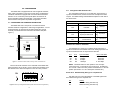
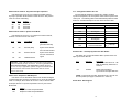
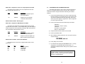
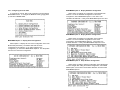
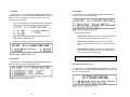
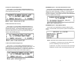
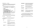
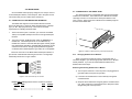
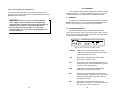
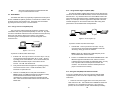
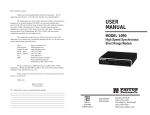
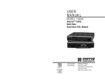
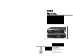
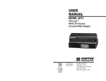
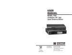
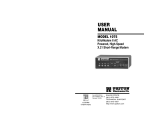
USER
MANUAL
MODEL 1092
High Speed, 2-Wire,
Sync & Async
Short Range Modem
Part# 07M1092-F
Doc# 033011UF
Revised 6/16/98
CERTIFIED
An ISO-9001
Certified Company
SALES OFFICE
(301) 975-1000
TECHNICAL SUPPORT
(301) 975-1007
http://www.patton.com
TABLE OF CONTENTS
Section
1.0 WARRANTY INFORMATION
Page
1.0 Warranty Information .............................................................2
1.1 Radio and TV Interference
1.2. CE Notice
1.3 Service Information
2.0 General Information ...............................................................4
2.1 Features
2.2 Description
3.0 Configuration .........................................................................5
3.1 Configuring the Hardware DIP Switches
3.1.1 Configuration Switch Set “S1”
3.1.2 Configuration Switch Set “S2”
3.2 Configuring the Software Switches
3.2.1 Configuring the Local 1092
3.2.2 Configuring the Remote 1092
3.3 Power Connection
4.0 Installation ...........................................................................21
4.1 Connecting the Twisted Pair Interface
4.2 Connecting the Serial Port
4.2.1 Changing QuikConnect™ Modules
4.2.2 Connecting a “DTE” Device
4.2.3 Connecting a “DCE” Device
4.2.4 Configuring the X.21 QuikConnect™ Module
4.3 Connecting Power
4.3 Control Port Interface
Connecting to an AC Power Source
Connecting to a DC Power Source
5.0 Operation .............................................................................26
5.1 Power- Up
5.2 LED Status Monitors
5.3 Test Modes
5.3.1 Using Local Line Loopback (LLB)
5.3.2 Using Remote Digital Loopback (RDL)
5.3.3 Using the V.52 (BER) Test Pattern Generator
Appendix A - Specifications ........................................................30
Appendix B - Factory Replacement Parts and Accessories .......31
Patton Electronics warrants all Model 1092 components to be
free from defects, and will—at our option—repair or replace the product
should it fail within one year from the first date of shipment.
This warranty is limited to defects in workmanship or materials,
and does not cover customer damage, abuse or unauthorized
modification. If this product fails or does not perform as warranted,
your sole recourse shall be repair or replacement as described above.
Under no condition shall Patton Electronics be liable for any damages
incurred by the use of this product. These damages include, but are
not limited to, the following: lost profits, lost savings and incidental or
consequential damages arising from the use of or inability to use this
product. Patton Electronics specifically disclaims all other warranties,
expressed or implied, and the installation or use of this product shall be
deemed an acceptance of these terms by the user.
1.1 RADIO AND TV INTERFERENCE
The Model 1092 generates and uses radio frequency energy, and
if not installed and used properly—that is, in strict accordance with the
manufacturer's instructions—may cause interference to radio and
television reception. The Model 1092 has been tested and found to
comply with the limits for a Class A computing device in accordance
with the specifications in Subpart J of Part 15 of FCC rules, which are
designed to provide reasonable protection from such interference in a
commercial installation. However, there is no guarantee that
interference will not occur in a particular installation. If the Model 1092
does cause interference to radio or television reception, which can be
determined by disconnecting the unit, the user is encouraged to try to
correct the interference by one or more of the following measures:
moving the computing equipment away from the receiver, re-orienting
the receiving antenna and/or plugging the receiving equipment into a
different AC outlet (such that the computing equipment and receiver are
on different branches).
1.2 CE NOTICE
The CE symbol on your Patton Electronics equipment indicates
that it is in compliance with the Electromagnetic Compatibility (EMC)
directive and the Low Voltage Directive (LVD) of the European Union
(EU). A Certificate of Compliance is available by contacting Technical
Support.
Appendix C - Interface Pin Assignments ....................................33
Appendix D - Control Port Pin assignments ...............................35
1
2
2.0 GENERAL INFORMATION
1.3 SERVICE
All warranty and non-warranty repairs must be returned freight
prepaid and insured to Patton Electronics. All returns must have a
Return Materials Authorization number on the outside of the shipping
container. This number may be obtained from Patton Electronics
Technical Service at
Thank you for your purchase of this Patton Electronics product.
This product has been thoroughly inspected and tested and is
warranted for One Year parts and labor. If any questions or problems
arise during installation or use of this product, please do not hesitate to
contact Patton Electronics Technical Support at (301) 975-1007.
2.1 FEATURES
tel: (301) 975-1007;
email: [email protected]
www: http://www.patton.com.
• Synchronous data rates: 19.2, 32, 56, 64 and 128 kbps
NOTE: Packages received without an RMA number will not be
accepted.
• Full duplex operation over a single twisted pair (2-wires)
Patton Electronics' technical staff is also available to answer any
questions that might arise concerning the installation or use of your
Model 1092. Technical Service hours: 8AM to 5PM EST, Monday
through Friday.
• Asynchronous data rates: 0 - 38.4 kbps
• Point-to-point distances up to 5 miles (all data rates) on
24 AWG twisted pair
• Remote digital loopback, local line loopback diagnostic modes
• Field Replaceable DTE-DCE interface modules:
V.24/RS-232, V.35, RS-422/530, G.703 and X.21
• Internal, external or receive recovered clocking options
• LED indicators for TD, RD, CTS, CD, DTR, TM, ER and NS
• Made in the U.S.A.
2.2 DESCRIPTION
The Patton Model 1092 is a high speed, AC powered short range
modem that is able to operate synchronously or asynchronously–full
duplex–over a single twisted pair. Supporting data rates to128kbps
(synchronous) or 38.4 kbps (asynchronous), the Model 1092 is capable
of point-to-point distances up to 5 miles using 24 AWG wire.
The Model 1092 supports internal, external or receive loopback
clocking in synchronous mode. Data rates and asynchronous data
format may be configured locally using DIP switches.
The Model 1092 features replaceable DCE-DTE interface
modules. Available interfaces include V.24/RS-232, V.35, RS-422/530,
G.703 and X.21. Line connection is made by RJ-45C jack. Internal AC
power supply options include 120/230VAC(switchable), and 100253VAC(universal). The internal DC power supply option supports any
DC input between 40-60VDC.
3
4
3.0 CONFIGURATION
3.1.1 Configuration DIP Switch Set “S1”
The Model 1092 is equipped with two sets of eight DIP switches,
which allow configuration of the unit to a wide variety of applications.
The Model 1092 is also equipped with an internal switch that allows
selection of 115 or 230 VAC power inputs (Note: this switch is not
present in Models 1092-UI and 1092-DC). This section describes
switch locations and explains all possible configurations.
3.1 CONFIGURING THE HARDWARE DIP SWITCHES
The configuration switches on S1 set data rate, asynchronous or
synchronous data format, transmit clock source and response to RDL
request. The default settings and detailed descriptions for each switch
are shown below.
S1 SUMMARY TABLE
Position
Function
Factory Default
S1-1
Data Rate
On
S1-2
Data Rate
Off
S1-3
DSR during Local Line Loop
On
S1-4
Async/Sync Data Format
Off
S1-5
Async/Sync Data Format
S1-6
Tx Clock Source
S1-7
Tx Clock Source
S1-8
Response to RDL Request
The Model 1092 uses a unique set of 16 external mini DIP
switches that allow configuration to wide range of applications. The 16
external switches are grouped into two eight-switch sets, and are
externally accessable from the underside of the Model 1092 (See
Figure 1).
S2
ON
Front
ON
1 2 3 4 5 6 7 8
OFF
S1
Figure 1. Underside of Model 1092, Showing Location of DIP Switches
The two sets of DIP switches on the underside of the Model 1092
will be referred to as S1 and S2. Figure 2 shows the orientation of all
DIP switches is the same with respect to “ON” and “OFF” positions.
ON
}
On
On }
Off
On
64K Sync
DSR On
Async/Sync
Internal Clock
Enable
Switches S1-1 and S1-2: Data Rate
ON
1 2 3 4 5 6 7 8
Back
}
Use Switches S1-1 and S1-2 to configure the asynchronous or
synchronous data rate of the Model 1092. Each setting represents one
synchronous data rate and one asynchronous data rate.
S1-1
On
Off
On
Off
S1-2
On
On
Off
Off
Sync Data Rate
32 Kbps
56 Kbps
64 Kbps
128 Kbps
Async. Data Rate
Reserved
Reserved
Reserved
0 - 38.4 kbps
NOTE: The Model 1092 can also operate at the 19.2 kbps
synchronous rate. To operate at 19.2 synchronous, set Switches
S1-1 and S1-2 both to the OFF position and Switch S2-1 to the ON
position (see Section 3.2.1 for a description of Switch S2-1).
Switch S1-3: Data Set Ready During Line Loopback Test
ON
Use Switch S1-3 to control the behavior of the DSR signal at the
EIA interface during the line loopback test.
1 2 3 4 5 6 7 8
OFF
Figure 2. Close Up of Configuration Switches (both sets are identical in appearance)
5
S-3
On
Off
Setting
DSR is on during local line loop
DSR is off during local line loop
6
Switches S1-4 and S1-5: Asynchronous/Sync Operation
3.1.2 Configuration Switch Set “S2”
Use Switches S1-4 and S1-5 to configure the Model 1092 for
async/sync operation. Both switches must be set in the “Off” position.
There is no other valid setting.
Use the eight DIP Switches in Switch S2 to enable 19.2 kbps
synchronous operation, set the loopback modes and the speed of the
control port. The following table summarizes default positions of DIP
Switch S2. Detailed descriptions of each switch follow the table.
S1-4
Off
On
Off
On
S1-5
Off
Off
On
On
Setting
Async/Sync
Reserved
Reserved
Reserved
S2 SUMMARY TABLE
Switches S1-6 and S1-7: System Clock Mode
Use Switches S1-6 and S1-7 to configure the 1092 for internal,
external, or receive recover clock mode.
S1-6
On
S1-7
On
Clock Mode
Internal
Description
System clock
generated internally
Off
On
External (DTE)
System clock derived
from terminal interface
On
Off
Receive Recover
System clock derived
from the received line
signal.
Off
Off
Hardware Reset
Important: A pair of Model 1092s communicate synchronously
across the twisted pair line connection. Therefore, you must set
these switches whether your application is async or sync.
For X.21 or Async applications, please configure one Model 1092
for internal clock mode and the other Model 1092 for receive
recover clock mode.
Switch S1-8: Response to RDL Request
Use Switch S1-8 to allow Model 1092 to enter the Remote Digital
Loopback diagnostic test when requested to do so by the far end Model
1092 For example, when Switch S1-8 is set to “ON”, it will enter RDL
mode (See Section 5.3.2) when requested to do so by the remote
Model 1092.
S1-8
On
Off
Position
Function
S2-1
19.2 kbps Enable
Off
S2-2
Not Assigned
Off
S2-3
Response to LAL from DTE
Off
S2-4
Not Assigned
Off
S2-5
Not Assigned
Off
S2-6
Response to RDL from DTE
On
S2-7
Control Port Data Rate
On
S2-8
Control Port Data Rate
On
Disabled
Enabled
}
9600 bpsc
Switches S2-1: 19.2 kbps Synchronous Rate Enable
Use Switch S2-1 to allow the Model 1092 to operate at the 19.2
kbps synchronous data rate.
S2-1
Off
Activation
Disabled
Description
Synchronous data rate is 32 - 128
kbps as defined by switches S1-1
and S1-2
On
Enabled
Model 1092 operates at
synchronous 19.2 kbps data rate*
*NOTE: To operate at 19.2 kbps, Set Switches S1-1 and S1-2 to
the OFF position (see page 6, Switches S1-1 and S1-2).
Switch S2-2: Not Assigned
Setting
Response to RDL Request Enabled
Response to RDL Request Disabled
7
Factory Default
8
Switch S2-3: Response to Local Line Loop Requests from DTE
3.2
Use Switch S2-3 to enable Local Line Loopback from the local
DTE interface (See Section 5.3.1).
The Model 1092 features a menu-driven command system that
allows you to configure either the local or remote 1092. Follow the
instructions below to configure the Model 1092 using the software
switches:
S2-3
Off
On
Activation
Disabled
Description
Ignore Line Loop Back request
from DTE interface
Enabled
CONFIGURING THE SOFTWARE SWITCHES
1)
Connect the serial RS-232 port of a V100 or similar DTE with
terminal emulation to the EIA/TIA-561l port of the Model 1092.
To construct an RS-232 to EIA-561 patch cable, refer to the
control port pinout diagram in Appendix D. Refer to Appendix
C to order a pre-made cable.
2)
Power up the terminal and set its RS-232 port as follows:
Respond to Line Loop Back
request from DTE interface
Switches S2-4 and S2-5: Not Assigned
Switch S2-6: Response to RDL Request from DTE
9600 Baud
8 data bits, i stop bit, no parity
Local echo
CR-CR/LF on inbound data
ANSI, VT-100 emulation
Use Switch S2-6 to determine the Model 1092 response to RDL
requests from the local DTE. In the enabled setting, the 1092 responds
to RDL requests from the local DTE by sending an RDL loop request to
the remote Model 1092 (See Section 5.3.2).
S2-3
Off
Activation
Disabled
Description
Ignore Remote Digital Loopback
request from DTE interface
On
Enabled
Respond to Remote Digital Loop
Back request from DTE interface
3)
Verify that switches S2-8 and S2-7 are set to ON.
4)
Power up the Model 1092.
5)
After the Model 1092 is powered on, the control port will send
out this message:
2W BBM, ver x.x
Switches S2-7 and S2-8: Control Port Data Rate
Use Switches S2-7 and S2-8 to configure Model 1092’s control
port bit rate.
S2-7
On
Off
On
Off
S2-8
On
On
Off
Off
Setting
9600 Bps (default)
19,2000 Bps
38,400 Bps
57,600 Bps
9
6)
Press [ESC] on the terminal.
7)
The 1092 will then display the MAIN MENU screen. You may
configure the LOCAL Model 1092 from this screen. To
configure the REMOTE Model 1092, press ‘$’ (Shift-4 on most
keyboards).
Important!!: To make a selection from any menu, enter
the option number. To exit any menu without making a
selection, or to return to the previous menu, press the
[ESC] key or the [SPACE] key.
10
3.2.1 Configuring the Local 1092
MAIN MENU Option 2: Display Hardware Configuration
To configure the LOCAL 1092, make a selection from the following
MAIN MENU screen. To configure the REMOTE 1092, type [$] (Shift4) and refer to Section 3.2.2.
Select Option 2 to display the configuration of the hardware DIPswitches. To use the Hardware Configuration for the Active
Configuration, select MAIN MENU Option 5. Then select “Use
Hardware DIP-Switches”. Finally, select MAIN MENU Option 8 to save.
MAIN MENU Option 3: Display Software Configuration
MAIN MENU Option 1: Display Active Configuration
Select Option 1 to display the most recent configuration of the local
Model 1092 (See below). The Model 1092 uses the active
configuration for its operation. If you make changes to the
configuration, you must select MAIN MENU Option 8. This will update
the unit to the new active configuration.
Select Option 3 to display the configuration of the software
switches. To use the software configuration for the Active
Configuration, select MAIN MENU, Option 5. Then select “Use
Software Switches”. Finally, select MAIN MENU Option 8 to save.
MAIN MENU Option 4: Setup Software Configuration
Select Option 4 toedit the software configuration of the Model 1092.
To save changes after editing the software configuration, select MAIN
MENU Option 5, then select “Use Software Switches” and then select
MAIN MENU Option 8.
11
12
1. DTE Rate
3. Clock Mode
Select Option 1 in the SOFTWARE CONFIGURATION menu to
select the async. or sync. DTE Rate of the Model 1092. Different DTE
Rate menu screens will display for async. or sync. bit rates. The
selections are shown below.
Select Option 3 in the SOFTWARE CONFIGURATION Menu to
select the sync clock mode (See below).
a) This menu is displayed when the data format is synchronous:
Set this option as follows:
Master Clock - Internal: Selection 1 allows the Model 1092
to generate an internal clock as the timing source.
b) This menu is displayed when the data format is asynchronous:
Master Clock - External: Selection 2 allows the Model
1092 to Derive the system clock from the locally connected
DTE.
Slaved to Receive Clock: Selection 3 to allows the Model
1092 to derive the timing source from the incoming data
stream from the remote Model 1092.
Important: One 1092A must be a Master Clock (either internal
or external) and the other must be Slaved to the Receive Clock.
2. Data Format
Select Option 2 in the SOFTWARE CONFIGURATION Menu to
select the async or sync data format (See below).
4. DSR During Local Line Loop
Select Option 4 in the SOFTWARE CONFIGURATION to configure
the behavior of the local Data Set Ready (DSR) signal during the Local
Line Loop test mode (below).
13
14
5. Response to Remote Digital Loop
MAIN MENU Option 5: Select Hardware/Software Control
Select Option 5 in the SOFTWARE CONFIGURATION Menu to
instruct the Model 1092 to either respond or ignore the Remote Digital
Loop request from the remote 1092.
Select Option 5 from the MAIN MENU selects whether the Model
1092 will use the hardware switch settings or the software switch
settings for its active configuration. If Options 1 or 2 are selected, the
1092RC will use the current hardware or software switch settings as
the active configuration. After changing this setting select MAIN MENU
Option 8 to implement the changes.
6. DTE Controlled Local Line Loop
MAIN MENU Option 6: Display Modem Status
Select Option 6 in the SOFTWARE CONFIGURATION Menu to
instruct the Model 1092 to either respond or ignore Local Line Loop
requests from the DTE. To instruct the Model 1092 to respond to
Local Line Loop requests from the DTE, select Enable (Option 1). To
instruct the 1092 to ignore Local Line Loop requests from the DTE
interface, select Disable (Option 2).
Select Option 6 from MAIN MENU to display the Modem Status
(below). Press RETURN on the keyboard to update and redisplay the
screen.
NOTE: Valid Model 1092 Handshake Statuses are listed below:
7. DTE Controlled Remote Digital Loop
Select Option 7 in the SOFTWARE CONFIGURATION Menu to
enable DTE control of the Remote Digital Loop Menu (See below). The
Remote Digital Loop on the 1092 can be controlled from the DTE
interface by selecting Enable (Option 1). To instruct the 1092 to ignore
this request from the DTE interface, select Disable (Option 2).
15
1) Handshaking - This status occurs when the 1092 is in the
process of establishing a link with another 1092.
2) Data Mode - This status occurs when the 1092 successfully
establishes a link with another 1092 allowing the data to flow.
16
MAIN MENU Option 7: Test Modes
Select Option 7 from the MAIN MENU to select the test mode status
of the Model 1092. (below). The Model 1092 Test Mode settings help
to verify the integrity of the data link and isolate communication
difficulties.
NOTE: An error counter is displayed when the unit is in one of
the above test modes except LLB and RDL.
To run or terminate a particular test, key in the option to get to that
screen menu. If a particular test cannot be invoked, the unit displays
the message:
“Attempt unsuccessful!”.
Local Line Loop
and 511 w/errors
Initiates the Local Line Loop test and starts
the internal 511 generator and detector. In
this test, the 511 pattern generator injects
intentional errors into the data stream.
Remote Digital
Loop
Initiates the Remote Digital Loopback test.
Any data sent to the remote 1092 is
returned to the originating device.
Remote Digital
Loop and 511
Initiates the Remote Digital Loopback test
and starts the internal 511 generator and
detectors.
Remote Digital
Loop and
511 with errors
Initiates the Remote Digital Loopback test
and starts the 511test patterns. In this test
the 511 pattern generator will inject initial
errors into the data stream.
The Modem Status Screen is displayed upon initiating a test.
A 511 error counter is displayed to indicate errors. Press the ‘C’
key to clear the counter and redisplay the Modem Status Screen.
Pressing ‘ESC’ returns you to the Test Mode Menu.
Pressing “C” will clear the error count and redisplay the
modem status screen. Pressing Return will update and redisplay
the status.
Test Mode options 2,3,7,8 and 9 require the 1092 to be in Data
Mode with the remote 1092. The Model 1092 Test Modes are
described below:
OFF
Terminates all tests
511
Initiates the built-in test pattern generator
and detector.
511 with Errors
Initiates the built-in test pattern generator
and detector. The test pattern generator
also injects intentional errors approximately
once per second.
Local Line Loop
and 511
Initiates the Local Line Loop test and starts
the internal 511 generator and detector.
17
18
3.2.2 Configuring the Remote 1092
REMOTE MAIN MENU Option 2: Remote Unit Configuration
To configure the Remote 1092, make a selection from the following
REMOTE UNIT CONFIGURATION MAIN MENU. To return to the
LOCAL 1092 MAIN MENU screen, press [ESC] and refer to Section
3.2.1.
REMOTE MAIN MENU Option 2 allows you to edit the software
configuration of the remote Model 1092. Please note that after editing
the software configuration, you must select REMOTE MAIN MENU
Option 4, the select “Use Software Switches” and then select MAIN
MENU Option 5 to implement the most recent changes.
REMOTE UNIT CONFIGURATION
MAIN MENU
1.
2.
3.
4.
5.
Display Remote Unit Configuration
Setup Remote Unit Configuration
Display Remote Modem Status
Select Hardware /Software Control
Restart Remote Unit
REMOTE UNIT CONFIGURATION MENU
1.
2.
3.
4.
5.
6.
7.
DTE Rate
Clock Mode
DSR during Local Line Loop
Response Remote Digital Loop
DTE Controlledl Local Line Loop
DTE Controlled Remote Digital Loop
2-Wire/4-Wire Selection (ONLY FOR 1092A)
REMOTE MAIN MENU Option 1: Display Remote Unit Configuration
Select Option 1 to display the configuration of various parameters in
the REMOTE Model 1092.
REMOTE MAIN MENU Option 3: Display Remote Modem Status
Select REMOTE MAIN MENU Option 3 to display the status of the
REMOTE unit.
REMOTE CONFIGURATION
CONFIGURATION DISPLAY MENU
REMOTE MAIN MENU Option 4: Display Hardware/Software Control
1. Display Configuration of:
DSR during Local Line Loop
Response to Remote Digital Loop
Clock Mode
Select REMOTE MAIN MENU Option 4 to select whether the
remote Model 1092 will use the hardware switch settings or the
software switch settings for its active configuration.
REMOTE MAIN MENU Option 5: Restart Remote Unit
2. Display Configuration of:
Configuration Control
DTE Rate
Select REMOTE MAIN MENU Option 5 to restart the remote unit.
3. Display Configuration of:
DTE Controlled Local Line Loop
DTE Controlled Remote Digital Loop
NOTE: All REMOTE CONFIGURATION sub-menus are
similar to the LOCAL CONFIGURATION sub-menu
screens.
19
20
4.0 INSTALLATION
4.2 CONNECTION TO THE SERIAL PORT
Once the Model 1092 is properly configured, it is ready to connect
to the twisted pair interface, to the serial port, and to the power source.
This section tells you how to make these connections.
4.1 CONNECTION TO THE TWISTED PAIR INTERFACE
The serial port interface on the Model 1092 uses interchangeable
QuikConnect™ Modules. Each QuikConnect™ Module has a 50-pin
card edge connector on one side and a serial port interface on the
other. Figure 4 below shows how a QuikConnect™ Module plugs into
the back of the Model 1092.
The Model 1092 supports communication between two DTE
devices at distances to 5 miles (24 AWG) and data rates to 128 kbps
(sync) or 38.4 kbps (asynchronous). There are two essential
requirements for installing the Model 1092:
1.
2.
These units work in pairs. Therefore, you must have one Model
1092 (or a compatible model) at each end of a single twisted pair
interface.
To function properly, the Model 1092 needs one twisted pair of
metallic wire. This twisted pair must be unconditioned, dry,
metallic wire, between 19 and 26 AWG (the higher number gauges
may limit distance somewhat). Standard dial-up telephone circuits,
or leased circuits that run through signal equalization equipment,
or standard, flat modular telephone type cable, are not acceptable.
e
Lin
ort
eP
ac
erf
Int
N
1O
FF
0O
Figure 4. Installation of Model 1092 Plug-in Serial Interface Module
The RJ-45 connector on the Model 1092’s twisted pair interface is
pre-wired for a standard TELCO wiring environment. The signal/pin
relationships are shown in Figure 3 below.
When you purchase a particular version of the Model 1092, it
should be shipped to you with the appropriate QuikConnect™ Module
already installed. If you need to install a different QuikConnect™
Module, follow these steps:
1 (N/C)
2 (N/C)
3 (N/C)
4 (Tip)
5 (Ring)
6 (N/C)
7 (N/C)
8 (N/C)
1
2
3
4
5
6
7
8
Removing the Existing QuikConnect™ Module
1) Turn the power switch off. Leave the power cord plugged into a
grounded outlet to keep the unit grounded.
2) Loosen the two thumbscrews on the module by turning them
counterclockwise.
Figure 3. Model 1092 twisted pair line interface.
Proper 2-Wire Pairing between the two modems is as follows:
SIGNAL
PIN#
PIN#
TIP
RING
4 ----------------------------------------4
5 ----------------------------------------5
21
4.2.1 Changing QuikConnect™ Modules
SIGNAL
3) Grasp the two thumbscrews and gently pull the module from the
unit. Apply equal force to the thumbscrews to keep the module
straight during the removal process.
TIP
RING
22
Installing the New QuikConnect™ Module
1) Make sure the power switch is off. Leave the power cord
plugged into a grounded outlet to keep the unit grounded.
2) Hold the module with the faceplate toward you and align the
module with the guide slots in the rear panel of the Model 1092.
3) While keeping the module’s faceplate parallel with the Model
1092 rear panel, slide the module straight in–so that the card
edge contacts line up with the socket inside the chassis.
NOTE: The card edge connector should meet the socket when
it is almost all the way into the chassis. If you encounter a lot of
resistance, remove the module and repeat steps 2 & 3.
4) With the card edge contacts aligned with the socket, firmly seat
the module by using your thumbs to apply pressure directly to
the right and left edges of the module faceplate. Applying
moderate and even pressure should be sufficient to seat the
module. You should hear it “click” into place.
5) To secure the module in place, push the thumbscrews into the
chassis and turn the screws clockwise to tighten.
4.2.2 Connection to a “DTE” Device
The serial port on most QuikConnect™ interface modules (all
except the X.21 module) is hard-wired as a DCE. Therefore these
modules “want” to plug into a DTE such as a terminal, PC or host.
When making the connection to your DTE device, use a straight
through cable of the shortest possible length—we recommend 6 feet
or less. When purchasing or constructing an interface cable, please
refer to the pin diagrams in Appendix D as a guide.
4.2.4 Configuring the X.21 QuikConnect™ Module
The serial port on the X.21 QuikConnect™ Module is default wired
as a DCE, but may be switched to a DTE. This is done by reversing
the orientation of the DCE/DTE strap, as described below:
To reverse DCE/DTE orientation, remove the module according to
the instructions in Section 4.2.1. The DCE/DTE strap is located on the
bottom side of the module’s PC board. The arrows on the top of the
strap indicate the configuration of the X.21 port (for example, if the DCE
arrows are pointing toward the DB-15 connector, the X.21 port is wired
as a DCE). Reverse the DCE/DTE orientation by pulling the strap out
of its socket, rotating it 180º, then plugging the strap back into the
socket. You will see that the DCE/DTE arrows now point in the
opposite directions, showing the new configuration of the X.21 port.
Reinstall the module according to the instructions in Section 4.2.1.
4.3 POWER CONNECTION
The Model 1092 is available with three power supply options:
Standard AC Power Supply option (Model 1092, no suffix) is
switchable between 100 and 253 VAC and is available with a
variety of domestic and international power cords. (See Appendix C).
Universal Interface AC Power Supply option (Model 1092-UI)
operates in environments ranging from 100 to 253 VAC, with no reconfiguration necessary (see Appendix C for available domestic and
international power cords).
DC Power Supply option (Model 1092-DC) operates in 48 VDC
environments and is equipped with a 3-pin “terminal strip” style
connector.
4.2.3 Connection to a “DCE” Device
4.3.1 Connecting to an AC Power Source
If the Model 1090’s QuikConnect™ interface module is hard-wired
as a DCE (all except the X.21 module), you must use a null modem
cable when connecting to a printer, modem, multiplexer or other DCE
device. This cable should be of the shortest possible length—we
recommend 6 feet or less. When purchasing or constructing a null
modem interface cable, use the pin diagrams in Appendix D as a
guide.
The two AC power supply options–Standard and Universal–are
equipped with a male IEC-320 power connection. A domestic (US)
NOTE: Pin-out requirements for null modem applications vary
widely between manufacturers. If you have any questions about a
specific application, contact Patton Technical Support.
23
power supply cord is supplied with the unit at no extra charge. To
connect the standard or universal power supply, follow these steps:
1)
Attach the power cord (supplied) to the shrouded male IEC-320
connector on the rear of the Model 1092.
2)
Plug the power cord into a nearby AC power outlet.
3)
Turn the rear power switch ON.
24
5.0 OPERATION
4.3.2 Connecting to a DC Power Source
The 48 VDC power supply option uses a 3-pin terminal block with
spring-type connectors. Please refer to the Model 1090 Series Service
Manual for further instructions.
Once the Model 1092 is properly configured and installed, it should
operate transparently. This sections describes power-up, reading the
LED status monitors, and using the built-in loopback test modes.
5.1 POWER-UP
WARNING!
There are no user-serviceable parts in the
power supply section of the Model 1092. Voltage setting
changes and fuse replacement should only be performed by
qualified service personnel. Contact Patton Electronics
Technical support at (301) 975-1007, via our website at
http://www.patton.com, or by e-mail at [email protected],
for more information.
To apply power to the Model 1092, first be sure that you have read
Section 4.3, and that the unit is connected to the appropriate power
source. Then power-up the unit using the rear power switch.
5.2 LED STATUS MONITORS
The Model 1092 features eight front panel LEDs that monitor
power, the DTE signals, network connection and test modes. Figure 5
(below) shows the front panel location of each LED. Following Figure 5
is a description of each LEDs function.
Model 1092 KiloModem 2W High Speed 2-Wire Short Range Modem
Test Modes
TD
RD
CTS
CD
DTR
NS
ER
TM
Local Normal Remote -
- 511E
- Normal
- 511
Control Port
Figure 5. Model 1092 Front Panel Installation of Model
25
TD & RD
Glows red to indicate an idle condition of Binary
“1” data on the respective terminal interface signals.
Green indicates Binary “0” data.
CTS
Glows green to indicate that the Clear to Send
signal from the modem is active.
CD
Glows red if no carrier signal is being received from
the remote modem. Green indicates that the remote
modem’s carrier is being received.
DTR
Glows green to indicate that the Data Terminal
Ready signal from the terminal is active.
ER
Glows red to indicate the likelihood of a Bit Error in
the received signal. During the 511 or 511/E test, ER
will flash to indicate that the Test Pattern Detector
has detected a bit error.
TM
Glows red to indicate that the Model 1092 has
been placed in Test Mode. The unit can be placed in
test mode by the local or remote user.
26
NS
Glow red to indicate that the local Model 1092 has
not yet connected with the remote
5.3 TEST MODES
The Model 1092 offers two proprietary loopback test modes, plus a
built-in V.52 BER test pattern generator, to evaluate the condition of the
modems and the communication link. These tests can be activated
physically from the front panel, or via the interface.
5.3.2 Using Remote Digital Loopback (RDL)
The Remote Digital Loopback (RDL) test checks the performance
of both the local and remote Model 1092s, and the communication link
between them. Any characters sent to the remote Model 1092 in this
test mode will be returned back to the originating device (see Figure 7,
below). For example, characters typed on the keyboard of the local
terminal will appear on the local terminal screen after having been
passed to the remote Model 1092 and looped back.
5.3.1 Using Local Line Loopback (LLB)
The Local Line Loopback (LLB) test checks the operation of the
local Model 1092, and is performed separately on each unit. Any data
sent to the local Model 1092 in this test mode will be echoed (returned)
back to the user device. (See Figure 6, below.) For example,
characters typed on the keyboard of a terminal will appear on the
terminal screen.
Figure 7. Remote Digital Loop
Local 1092
To perform an RDL test, follow these steps:
1.
Figure 6. Local Line Loop
NOTE: Switch S1-8 (Response to RDL Request) on the
remote Model 1092 must be enabled.
To perform a LLB test, follow these steps:
1.
Activate LLB. This may be done in one of two ways: First, by
moving the front panel toggle switch UP to “Local”. Second,
by raising pin 18 on the interface. Once LLB is activated, the
Model 1092 transmitter output is connected to its own
receiver. The “TM” LED should be lit.
2.
Verify that the data terminal equipment is operating properly
and can be used for a test. If a fault is indicated, call a
technician or replace the unit.
3.
Perform a V.52 BER (bit error rate) test as described in
Section 5.3.3. If the BER test equipment indicates no faults,
but the data terminal indicates a fault, follow the
manufacturer’s checkout procedures for the data terminal.
Also, check the interface cable between the terminal and the
Model 1092.
Activate RDL. This may be done in two ways: first, by
moving the front panel toggle switch DOWN to “Remote”.
Second, by raising pin 21 on the interface.
2.
Perform a V.52 BER test as described in Section 5.3.3. If the
BER test equipment indicates a fault, and the Local Line
Loopback test was successful for both Model 1092s, you may
have a problem with the twisted pair line between the
modems. You should then check the twisted pair line for
proper connections and continuity.
5.3.3 Using the V.52 (BER) Test Pattern Generator
27
To use the V.52 BER tests in conjunction with the Remote Digital
Loopback tests (or with Local Line Loopback tests), follow these
instructions:
1. Locate the “511/511E” toggle switch on the front panel of the
1092 and move it UP. This activates the V.52 BER test mode and
transmits a “511” test pattern into the loop. If any errors are
present, the local modem’s red “ER” LED will blink sporadically.
28
APPENDIX A
2.
If the above test indicates no errors are present, move the
V.52 toggle switch DOWN, activating the “511/E” test with
errors present. If the test is working properly, the local
modem's red “ER” LED will glow. A successful “511/E” test
will confirm that the link is in place, and that the Model 1092’s
built-in “511” generator and detector are working properly.
PATTON MODEL 1092 SPECIFICATIONS
Transmission Format: Synchronous or asynchronous
Transmission Line: Single unconditioned twisted pair
Clocking: Internal, external or receive loopback
NOTE: The above V.52 BER tests can be used independently
of the Remote Digital Loopback tests. This requires two
operators: one to initiate and monitor the tests at the local
Model 1092, and one to do the same at the remote Model
1092. In this case, the test pattern sent by each Model 1092
will not be looped back, but will be transmitted down the line to
the other Model 1092. While one operator initiates test, the
other monitors for errors.
Distance: Distance, max, all data rates:
10.1 miles (16.4km) on 19 AWG (0.9mm) wire
7.2 miles (11.5 km) on 22 AWG (0.64mm) wire
5.0 (8 km) on 24 AWG (0.5mm) wire
3.4 (5.5 km) on 26 AWG (0.4mm) wire
Interface Modules: EIA RS-232/CCITT V.24, RS-232/530,
CCITT V.35 and CCITT X.21
Data Rates: Synchronous 32, 56, 64 & 128 kbps; Asynchronous
0 - 38.4 kbps
Diagnostics: V.52 compliant bit error rate pattern (511/511E
pattern) generator and detector with error injection mode; Local
Line Loopback and Remote Digital Loopback, activated by front
panel switch or via serial interface
LED Status Indicators: TD, RD, CTS, CD, DTR, NS(no signal),
ER (error) and TM (test mode)
Connectors: RJ-45 on line side; DB-25 female, M/34 female or
DB-15 female on serial interface side, depending upon which
interface module is installed.
Power: 120/230 VAC (switch selectable), 50-60 Hz; 100-253 VAC,
50-60 Hz (universal input option); 48 VDC (option). 5 watts.
Temperature Range: 32-122°F (0° -50°C)
Altitude: 0-15,000 feet
Humidity: 5 to 95% noncondensing
Dimensions:
7.3” x 6.6” x 1.62” (185mm x 168mm x 41mm)
Weight: 2.01 lbs. (1.0kg)
29
30
APPENDIX B
APPENDIX C
PATTON MODEL 1092 FACTORY REPLACEMENT PARTS
AND ACCESSORIES
PATTON MODEL 1092 INTERFACE PIN ASSIGNMENT
Patton Model #
Description
IM1/A...............................V.24 with DB25F
IM1/B ...............................RS422/RS530 with DB25F
IM1/C...............................V.35 with M34F
IM1/D...............................X.21 with DB15F
IM1/E ...............................V.35 with DB25F
IM1/F ...............................G.703 with RJ45
0805US ...........................American Power Cord
0805EUR.........................European Power Cord CEE 7
0805UK ...........................United Kingdom Power Cord
0805AUS .........................Australia/New Zealand Power Cord
0805DEN.........................Denmark Power Cord
0805FR............................France/Belgium Power Cord
0805IN.............................India Power Cord
0805IS .............................Israel Power Cord
0805JAP..........................Japan Power Cord
0805SW...........................Switzerland Power Cord
07M1090SVC ..................1090 Series Service Manual
31
RS-232, RS-530 Interface Pin Description
(DB-25 Female Connector)
(DCE Configuration)
Pin #
1
2
3
4
5
6
7
8
9
10
11
12
13
14
15
16
17
18
19
20
21
22
23
24
25
Signal
FG (Frame Ground)
TD (Transmit Data)
RD (Receive Data)
RTS (Request to Send)
CTS (Clear to Send)
DSR (Data Set Ready)
SGND (Signal Ground)
CD (Carrier Detect)
RC/ (Receive Timing-B)
CD/ (Carrier Detect-B)
XTC/ (External Transmit Clock)
TC/ (Test Control-B)
CTS/ (Clear to Send)
TD/ (Transmit Data-B)
TC (Test Control-A)
RD (Receive Data)
RC (Receive Timing)
LLB (Local Line Loop)
RTS/ (Request to Send)
DTR (Data Transfer Rate)
DL (Remote Digital Loop)
DSR/ (Data Set Ready)
DTR/ (Data Transfer Rate)
XTC (External Transmit Clock)
TM (Test Mode)
32
APPENDIX C
APPENDIX C
PATTON MODEL 1092 INTERFACE PIN ASSIGNMENT
(Continued)
PATTON MODEL 1092 INTERFACE PIN ASSIGNMENT
(Continued)
V.35 Interface
(M/34F Female Connector)
(DCE Configuration)
X.21 Interface
(DB-15 Female Connector)
(DTE /DCE Configuration)
Signal
Pin #
B ...........................SGND (Signal Ground)
C ...........................RTS (Request to Send)
D ...........................CTS (Clear to Send)
E ...........................DSR (Data Set Ready)
F............................CD (Carrier Detect)
H ...........................DTR (Data Transfer Ready)
L............................LLB (Local Line Loop)
M ...........................TM (Test Mode)
N ...........................RDL (Remote Digital Loop)
P ...........................TD(Transmit Data)
R ...........................RD (Receive Data)
S ...........................TD/ (Transmit Data-B)
T............................RD/ (Receive Data-B)
U ...........................XTC (External Transmit Clock)
V ...........................RC(Receive Timing)
W ...........................XTC/ (External Transmit Clock)
X ...........................RC/ (Receive Timing)
Y ...........................TC(Test Control-A)
AA ..........................TC/ (Test Control-B)
33
Signal
Pin #
1 . . . . . . . . . . . . Frame Ground
2 . . . . . . . . . . . . T (Transmit Data-A)
3 . . . . . . . . . . . . C (Control-A)
4 . . . . . . . . . . . . R (Receive Data-A)
5 . . . . . . . . . . . . I (Indication-A)
6 . . . . . . . . . . . . S (Signal Element iming-A)
7 . . . . . . . . . . . . BT (Byte Timing-A)
8 . . . . . . . . . . . . SGND (Signal Ground)
9 . . . . . . . . . . . . T/ (Transmit Data-B)
10 . . . . . . . . . . . C/ (Control-B)
11. . . . . . . . . . . . R/ (Receive Data-B)
12 . . . . . . . . . . . I/ (Indication-B)
13 ........................S/ (Signal Element Timing-B)
14 .......................BT/ (Byte Timing-B)
34
Dear Valued Customer,
APPENDIX D
PATTON MODEL 1092 Pin Out Control Port
The 1092 control port is an 8 position connector, compliant with
EIA/TIA-561.
RJ45 Pin No.
Pin Function
Ground
4
Receive data (to DTE)
5
Transmit data (from DTE)
6
Thank you for purchasing Patton Electronics products! We do
appreciate your business. I trust that you find this user manual helpful.
We manufacture one of the widest selections of data
communications products in the world including CSU/DSU's, network
termination units, powered and self-powered short range modems, fiber optic
modems, interface converters, baluns, electronic data switches, data-line surge
protectors, multiplexers, transceivers, hubs, print servers and much more. We
produce these products at our Gaithersburg, MD, USA, facility, and can
custom manufacture products for your unique needs.
We would like to hear from you. Please contact us in any of the
following ways to tell us how you like this product and how we can meet your
product needs today and in the future.
Web:
Sales E-mail:
Support E-mail:
Phone - Sales
Phone - Support
Fax:
Mail:
http://www.patton.com
[email protected]
[email protected]
(301) 975-1000
(301) 975-1007
(301) 869-9293
Patton Electronics Company
7622 Rickenbacker Drive
Gaithersburg, MD 20879 USA
We are committed to a quality product at a quality price. Patton
Electronics is BABT and ISO 9001 certified. We meet and exceed the highest
standards in the industry (CE, UL, etc.).
It is our business to serve you. If you are not satisfied with any
aspect of this product or the service provided from Patton Electronics or its
distributors, please let us know.
Thank you.
Burton A.Patton
Vice President
P.S. Please tell us where you purchased this product.
_______________________________________________________________
_______________________________________________________________
_______________________________________________________________
_______________________________________________________________
_______________________________________________________________
_______________________________________________________________
______________________________________________________________
35