1
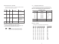
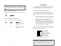
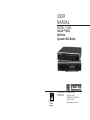
USER
M A N UA L
MODEL 1094A
NetLink™ HDSL
Multi-Rate
Symmetric DSL Modem
Part# 07M1094A-B
Doc# 032042UB
Revised 07/22/99
CERTIFIED
An ISO-9001
Certified
Company
SALES OFFICE
(301)975-1000
TECHNICAL SUPPORT
(301)975-1007
http://www.patton.com
1.0 WARRANTY INFORMATION
TABLE OF CONTENTS
SECTION
PAGE
1.0 Warranty Information .............................................................2
1.1 Radio and TV Interference
1.2. CE Notice
1.3 Service
2.0 General Information...............................................................4
2.1 Features
2.2 Description
3.0 Configuration .........................................................................5
3.1 Configuring the Hardware DIP Switches
3.1.1 Configuration DIP Switch Set “S1”
3.1.2 Configuration DIP Switch Set “S2”
3.1.3 Configuration DIP Switch Set “S3”
4.0 Installation ...........................................................................10
4.1 Connecting the Twisted Pair Interface
4.2 Connecting the Serial Port
4.2.1 Changing QuikConnect™ Modules
4.2.2 Connecting a “DTE” Device
4.2.3 Connecting a “DCE” Device
4.2.4 Configuring the X.21 QuikConnect™ Module
4.3 Connecting Power
4.3.1 Connecting to an AC Power Source
4.3.2 Connecting to a DC Power Source
5.0 Operation .............................................................................15
5.1 Power-Up
5.2 LED Status Monitors
5.3 Test Modes
5.3.1 Overview
5.3.2 Loops and Patterns
5.3.3 Using the V.52 (BER) Test Pattern Generator
Appendix A - Specifications........................................................26
Appendix B - Factory Replacement Parts and Accessories.......27
Appendix C - Interface Pin Assignments....................................28
Patton Electronics warrants all Model 1094A components to be
free from defects, and will—at our option—repair or replace the product should it fail within one year from the first date of shipment.
This warranty is limited to defects in workmanship or materials,
and does not cover customer damage, abuse or unauthorized modification. If this product fails or does not perform as warranted, your sole
recourse shall be repair or replacement as described above. Under no
condition shall Patton Electronics be liable for any damages incurred
by the use of this product. These damages include, but are not limited
to, the following: lost profits, lost savings and incidental or consequential damages arising from the use of or inability to use this product.
Patton Electronics specifically disclaims all other warranties,
expressed or implied, and the installation or use of this product shall
be deemed an acceptance of these terms by the user.
1.1 RADIO AND TV INTERFERENCE
The Model 1094A generates and uses radio frequency energy,
and if not installed and used properly—that is, in strict accordance with
the manufacturer's instructions—may cause interference to radio and
television reception. The Model 1094A has been tested and found to
comply with the limits for a Class A computing device in accordance
with the specifications in Subpart J of Part 15 of FCC rules, which are
designed to provide reasonable protection from such interference in a
commercial installation. However, there is no guarantee that interference will not occur in a particular installation. If the Model 1094A does
cause interference to radio or television reception, which can be determined by disconnecting the unit, the user is encouraged to try to correct the interference by one or more of the following measures: moving the computing equipment away from the receiver, re-orienting the
receiving antenna and/or plugging the receiving equipment into a different AC outlet (such that the computing equipment and receiver are
on different branches).
1.2 CE NOTICE
The CE symbol on your Patton Electronics equipment indicates
that it is in compliance with the Electromagnetic Compatibility (EMC)
directive and the Low Voltage Directive (LVD) of the European Union
(EU). A Certificate of Compliance is available by contacting Technical
Support.
Appendix D - Transmission Distance Chart ...............................31
1
2
2.0 GENERAL INFORMATION
1.3 SERVICE
All warranty and non-warranty repairs must be returned freight
prepaid and insured to Patton Electronics. All returns must have a
Return Materials Authorization number on the outside of the shipping
container. This number may be obtained from Patton Electronics
Technical Service at:
Thank you for your purchase of this Patton Electronics product.
This product has been thoroughly inspected and tested and is warranted for One Year parts and labor. If any questions or problems arise
during installation or use of this product, please do not hesitate to contact Patton Electronics Technical Support at (301) 975-1007.
2.1 FEATURES
Tel:
(301)975-1007
Email: [email protected]
www: http://www.patton.com
NOTE:
Packages received without an RMA number will not be
accepted.
Patton Electronics' technical staff is also available to answer any
questions that might arise concerning the installation or use of your
Model 1094A. Technical Service hours: 8AM to 5PM EST, Monday
through Friday.
•
•
•
•
•
DSL Distances on just two wires using HDSL technology
DTE Speeds n x 64 to 1.152 Mbps
2-wire Operation
Standalone (QuikConnect™) and Rackmount Versions Available
SNMP Network Management with In-Band Management of Remote
Units plus Advanced Diagnostics & Statistics using Patton Model
1000MC
• Internal, external or receive recovered clocking options
• LED indicators for TD, RD, CTS, CD, DTR, TM, ER and NS
2.2 DESCRIPTION
IMPORTANT:
The Model 1094A is equipped with flash
upgrade. Please refer to Patton website, http://www.patton.com
or contact Technical Support for the latest version of the software.
The Patton Electronics NetLinkTM HDSL Multi-Rate DSL Modem
provides high speed 2-wire connectivity to ISPs, PTTs, and corporations using HDSL (Multi-rate Digital Subscriber Line) technology.
Multi-rate DSL offers the ability to deliver the maximum bit rate that a
twisted pair line can accommodate. Supporting multiple line rates from
144kbps to1.168 Mbps, the NetLink provides “megabyte” speeds to
leased line, LAN to LAN interconnection, and WAN access networks
over 2.9 miles/4.7km (1.152Mbps on 24AWG/.5mm wire).
The NetLinkTM HDSL standalone allows DTE speeds from
64kbps to 1.152Mbps in increments of 64kbps. Features include loopback diagnostics, inband SNMP/HTTP remote management capabilities and externally accessible configuration switches. A high density
2U-high rack card version of the NetLinkTM HDSL is also available.
As a symmetric DSL NTU, NetLinkTM HDSL offers the same data
rates in both directions over a single pair of regular telephone lines
using 2B1Q modulation. Featuring replaceable DCE-DTE interface
modules, the NetLink HDSL can be configured for a huge range of
V.24/RS-232, V.35, RS-422/530, G.703 and X.21 applications. Line
connection is made by an RJ-45 jack. The standard Model 1094A is
powered by a 100/230VAC(Universal) supply. The DC power supply
option supports any DC input between 40-60VDC.
3
4
3.0 CONFIGURATION
3.1.1 Configuration DIP Switch Set “S1” - Reserved Switches
The Model 1094A is equipped with three sets of eight DIP switches, which allow configuration of the unit for a wide variety of applications. This section describes switch locations and explains all possible
configurations.
All Switches in Switch S1 are reserved for future use. These
switches should remain in the On position.
3.1 CONFIGURING THE HARDWARE DIP SWITCHES
3.1.2 Configuration DIP Switch Set “S2”
The 24 external switches are grouped into three eight-switch sets,
and are externally accessible from the underside of the Model 1094A
(See Figure 1).
The configuration switches on S2 allow you to specify the Clocking
Mode and response to DTE Loop Enable. Default settings of S2 are
shown in the table below.
On
S3
Back
Front
S2
S1
Off
Position
S2-1
S2-2
S2-3
S2-4
S2-5
S2-6
S2-7
S2-8
S2 SUMMARY TABLE
Function
Factory Default
Reserved
Off
Reserved
Off
Reserved
Off
Reserved
Off
Reserved
Off
Clock Mode
On Receive
Clock Mode
Off Recovered Clock
Enable Loop from DTE Off Disable
Switch S2-1, S2-2, S2-3, S2-4, and S-5: Reserved for Future
Use and Should Remain in the Off Position.
Figure 1. Underside of Model 1094A, Showing Location of DIP Switches
The three sets of DIP switches on the underside of the Model
1094A will be referred to as S1, S2, and S3. As Figure 2 shows, the
orientation of all DIP switches is the same with respect to “ON” and
“OFF” positions.
ON
ON
1
2
3
4
5
6
7
8
OFF
Figure 2. Close Up of Configuration Switches (all sets are identical in appearance)
5
6
3.1.3
Switches S2-6 and S2-7: Clock Mode
Use Switches S2-6 and S2-7 to configure the 1094A for internal,
external, or receive recover clock mode.
CO/CP
Unit
CO
CO
CP
S2-6
On
Off
On
Off
S2-7
On
On
Off
Clock Mode
Internal
External (DTE)
Receive Recover
Description
Transmit clock
generated internally
Transmit clock
derived from
terminal interface
Transmit clock
derived from the
received line
Configuration Switch Set “S3”
Use the eight DIP Switches in Switch S3 to enable the DTE connection rate. The following table summarizes default positions of DIP
Switch S3. Detailed descriptions of each switch follow the table.
S3 SUMMARY TABLE
Position
Function
Factory Default
S3-1
DTE Rate
Off
S3-2
DTE Rate
Off
S3-3
DTE Rate
On
S3-4
DTE Rate
On
S3-5
DTE Rate
On
S3-6
DTE Rate
On
}
Reset Software Defaults
On
Normal Operation
Transmit Data Sample Point On
Normal Operation
S3-7
S3-8
64Kbps
Reserved
Off
Switch S3-1: DTE Rate
Switch S2-8: Enable/Disable Loop Tests from DTE
Use Switch S2-8 to allow Model 1094A to enter loopback tests
when the DTE raises the appropriate loop request pin.
S2-8
On
Off
Setting
Response to DTE Loopback Request Enabled
Response to DTE Loopback Request Disabled
7
Use Switch S3-1 through S3-6 to set the DTE bit rate.
S3-1
Off
On
Off
On
Off
On
Off
On
Off
On
Off
On
Off
On
Off
On
Off
On
S3-2
Off
On
On
Off
Off
On
On
Off
Off
On
On
Off
Off
On
On
Off
Off
On
S3-3
On
Off
Off
Off
Off
On
On
On
On
Off
Off
Off
Off
On
On
On
On
Off
S3-4
On
On
On
On
On
Off
Off
Off
Off
Off
Off
Off
Off
On
On
On
On
On
S3-5
On
On
On
On
On
On
On
On
On
On
On
On
On
Off
Off
Off
Off
Off
8
S3-6
On
On
On
On
On
On
On
On
On
On
On
On
On
On
On
On
On
On
DTE Rate (kbps)
64
128
192
256
320
384
448
512
576
640
704
768
832
896
960
1024
1088
1152
4.0 INSTALLATION
NOTE:
Based upon the chosen DTE rate, the Model 1094A
will automatically select the optimum line rate for distance. This
selection is based on the lowest line rate that will support the
DTE rate.
Once the Model 1094A is properly configured, it is ready to connect to the twisted pair interface, to the serial port, and to the power
source. This section tells you how to make these connections.
Switch S3-7: Reset Software Defaults
4.1 CONNECTING THE TWISTED PAIR INTERFACE
Switch S3-7 allows the user to reset the software configured factory defaults.
The Model 1094A supports communication between two DTE
devices at distances to 4 miles (8 km) over 24 AWG (.5mm) twisted
pair wire. There are two essential requirements for installing the Model
1094A:
S3-7
On
Off
Factory Test
Normal Operation
Reset
1. These units work in pairs. Both units at the end of the twisted
pair must have the same 2-Wire connection and DTE rate.
Switch S3-8: Transmit Data (TD) Sampling Point
Switch 3-8 controls the Transmit Data (TD) sampling point.
S3-8
On
Setting
Normal
Description
TD sampled on the falling
edge of the 1094A Transmit
Clock (TC)
Off
Invert
TD sampled on the rising
edge of the 1094A Transmit
Clock.
2.
To function properly, the Model 1094A needs one
twisted pair of metallic wire. This twisted pair must be
unconditioned, dry, metallic wire, between 19 (.9mm) and 26
AWG (.4mm) (the higher number gauges will limit distance).
Standard dial-up telephone circuits, or leased circuits that run
through signal equalization equipment, or standard, flat modular telephone type cable, are not acceptable.
The RJ-45 connector on the Model 1094A’s twisted pair interface is
polarity insensitive and is wired for a two-wire interface. The signal/pin
relationships are shown in Figure 3 below.
1
2
3
4
5
6
7
8
1
2
3
4
5
6
7
8
(N/C)
(N/C)
(N/C)
(2-Wire TIP)
(2-Wire RING)
(N/C)
(N/C)
(N/C)
Figure 3. Model 1094A twisted pair line interface.
IMPORTANT!:
The Model 1094A has been optimized for
performance at high bitrates (DTE rates greater than 512 kbps).
To ensure accurate performance at these bit rates, please use
twisted pair line interface cable that is at least 330ft (100m) in
length.
9
10
4.2 CONNECTING THE SERIAL PORT
The serial port interface on the Model 1094A uses interchangeable QuikConnect™ Modules. Each QuikConnect™ Module has a
50-pin card edge connector on one side and a serial port interface on
the other. Figure 4 below shows how a QuikConnect™ Module plugs
into the back of the Model 1094A.
2) Hold the module with the faceplate toward you and align the
module with the guide slots in the rear panel of the Model
1094A.
3) While keeping the module’s faceplate parallel with the Model
1094A rear panel, slide the module straight in – so that the
card edge contacts line up with the socket inside the chassis.
NOTE:
The card edge connector should meet the socket when
it is almost all the way into the chassis. If you encounter a lot of
resistance, remove the module and repeat steps 2 & 3.
e
Lin
rt
Po
ce
rfa
Inte
N
1O
FF
0O
Figure 4. Installation of Model 1094A Plug-in Serial Interface Module
4.2.1 Changing QuikConnect™ Modules
When you purchase a particular version of the Model 1094A, it
should be shipped to you with the appropriate QuikConnect™ Module
already installed. If you need to install a different QuikConnect™
Module, follow these steps:
Removing the Existing QuikConnect™ Module
1) Turn the power switch off. Leave the power cord plugged into
a grounded outlet to keep the unit grounded.
2) Loosen the two thumbscrews on the module by turning them
counterclockwise.
3) Grasp the two thumbscrews and gently pull the module from
the unit. Apply equal force to the thumbscrews to keep the
module straight during the removal process
Installing the New QuikConnect™ Module
4) With the card edge contacts aligned with the socket, firmly seat
the module by using your thumbs to apply pressure directly to
the right and left edges of the module faceplate. Applying
moderate and even pressure should be sufficient to seat the
module. You should hear it “click” into place.
5) To secure the module in place, push the thumbscrews into the
chassis and turn the screws clockwise to tighten.
4.2.2 Connecting to a “DTE” Device
The serial port on most QuikConnect™ interface modules (all
except the X.21 module) is hard-wired as a DCE. Therefore these
modules “want” to plug into a DTE such as a terminal, PC or host.
When making the connection to your DTE device, use a straight
through cable of the shortest possible length—we recommend 6 feet
or less. When purchasing or constructing an interface cable, please
refer to the pin diagrams in Appendix C as a guide.
4.2.3 Connecting to a “DCE” Device
If the Model 1094A’s QuikConnect™ interface module is hardwired as a DCE (all except the X.21 module), you must use a null
modem cable when connecting to a modem, multiplexer or other DCE
device. This cable should be of the shortest possible length—we recommend 6 feet or less. When purchasing or constructing a null
modem interface cable, use the pin diagrams in Appendix C as a
guide.
NOTE:
Pin-out requirements for null modem applications
vary widely between manufacturers. If you have any questions
about a specific application, contact Patton Electronics
Technical Support.
1) Make sure the power switch is off. Leave the power cord
plugged into a grounded outlet to keep the unit grounded.
11
12
4.3.2 Connecting to a DC Power Source
4.2.4 Configuring the X.21 QuikConnect™ Module
The serial port on the X.21 QuikConnect™ Module is default wired
as a DCE, but may be switched to a DTE. This is done by reversing
the orientation of the DCE/DTE strap, as described below:
To reverse DCE/DTE orientation, remove the module according to
the instructions in Section 4.2.1. The DCE/DTE strap is located on
the bottom side of the module’s PC board. The arrows on the top of
the strap indicate the configuration of the X.21 port (for example, if the
DCE arrows are pointing toward the DB-15 connector, the X.21 port is
wired as a DCE). Reverse the DCE/DTE orientation by pulling the
strap out of its socket, rotating it 180º, then plugging the strap back
into the socket. You will see that the DCE/DTE arrows now point in
the opposite directions, showing the new configuration of the X.21
port. Reinstall the module according to the instructions in Section
4.2.1.
The 48 VDC power supply option uses a 3-pin terminal block with
spring-type connectors. Please refer to the Model 1090 Series Service
Manual for the power line voltage connections.
WARNING!
There are no user-serviceable parts in the power
supply section of the Model 1094A. Fuse replacement should
only be performed by qualified service personnel. Contact
Patton Electronics Technical support at (301) 975-1007, via our
web site at http://www.patton.com, or by e-mail at [email protected], for more information.
4.3 CONNECTING POWER
The Model 1094A is available with two power supply options:
Universal Interface AC Power Supply option (Model 1094A-UI)
operates in environments ranging from 100 to 253 VAC, with no reconfiguration necessary (see Appendix B for available domestic and
international power cords).
DC Power Supply option (Model 1094A-DC) operates in 48 VDC
environments and is equipped with a 3-pin “terminal strip” style connector.
4.3.1 Connecting to an AC Power Source
The Universal Interface AC Supply is equipped with a male IEC320 power connection. A domestic (US) power supply cord is supplied with the unit at no extra charge. To connect the standard or universal power supply, follow these steps:
1)
Attach the power cord (supplied) to the shrouded male IEC320 connector on the rear of the Model 1094A.
2)
Plug the power cord into a nearby AC power outlet.
3)
Turn the rear power switch ON.
13
14
5.0 OPERATION
ER
- blinks ON/OFF after a 511/511E test has timed
out. See Section 5.3.3 (Test Pattern Generator) for
more information.
Once the Model 1094A is properly configured and installed, it
should operate transparently. This sections describes power-up, reading the LED status monitors, and using the built-in loopback test
modes.
5.1 POWER-UP
- flashes once to indicate that a CRC error has
occurred (during normal operation) or bit errors
have occurred (during 511/511E tests).
To apply power to the Model 1094A, first be sure that you have
read Section 4.3, and that the unit is connected to the appropriate
power source. Then power-up the unit using the rear power switch.
- Only at power up, blinks once every 200 ms if
the DTE Rate is set to an unsupported settings
5.2 LED STATUS MONITORS
TM
The Model 1094A features eight front panel LEDs that monitor
power, the DTE signals, network connection and test modes. Figure 5
(below) shows the front panel location of each LED. Following Figure
5 is a description of each LEDs function.
glows yellow to indicate that the Model 1094A
has been placed in Test Mode. The unit can be
placed in test mode by the local user or by the
remote user.
NS
(No Signal) glows red to indicate that the local
Model 1094A is not connected with the remote
Model 1094A.
Model 1092 KiloModem 2W High Speed 2-Wire Short Range Modem
5.3 TEST MODES
Test Modes
TD
RD
CTS
CD
DTR
NS
ER
TM
Local Normal Remote -
- 511E
- Normal
- 511
Control Port
Figure 5. Model 1094A Front Panel
TD & RD
The Model 1094A offers two proprietary loopback test modes, plus
a built-in V.52 BER test pattern generator to evaluate the condition of
the modems and the communication link. These tests can be activated physically from the front panel or via the DTE interface.
Glows yellow to indicate an idle condition of Binary
“1” data on the respective terminal interface signals. Green indicates Binary “0” data
5.3.1 Overview
CTS
Glows green to indicate that the Clear to Send signal from the modem is active.
Figure 6 below shows the major elements used in the loop-back
and pattern tests available in the Model 1094A. Each block has several functions. Following Figure 6 are descriptions that show how the
elements are used during Test Modes.
CD
Glows yellow if no carrier signal is being received
from the remote modem. Green indicates that the
remote modem’s carrier is being received.
DTR
Glows green to indicate that the Data Terminal
Ready signal from the terminal is active.
Framer
Pattern
Gen/Det
Loop
Control
Line
Processor
Loop
Control
Processor
Figure 6: Block Diagram Model 1094A
15
16
Pattern
Gen/Det
Framer
Framer
The framer is used to determine the status of
the line. In normal operation the framer transmits and expects to receive framed packets
from the far end. If the framer receives framed
packets from the far end, CTS and CD will be
active. If framed packets are not received, CTS
and CD will be inactive. The restart procedure
uses this information to determine if a valid connection is made (cable disconnect, poor cable
quality, etc). In normal Data Mode, if the box
receives 4 seconds of unframed packets it will
restart the box and begin trying to re-establish a
connection with the far end. The distinction
between framed packets and unframed packets
becomes important when we discuss the Pattern
Generator.
Pattern Gen/Det
This part of the Processor generates and
detects the 511/511E patterns. When transmitting 511 patterns, the information is unframed
(because it originates after the framer) and is
intended to be evaluated only by another
Processor. If the units are in Data Mode and the
pattern generator is enabled on one end of the
link, the far end will begin receiving unframed
packets and assume that the line has gone
down. During test modes, we force the pattern
generator to time out before it can cause the link
to be killed.
Restart Procedure
and Time Outs
Item
The restart procedure is in place to allow the
units to re-establish a connection after the
framer begins seeing unframed packets. The
Test Model Timing Chart below shows the
amount of time the framer must see consecutive
unframed packets before the unit will restart and
try to establish a new line connection. The reason that there are different Restart Times will
become apparent after reading the rest of the
document. The 511/511E Time Out shown refers
to the amount of time the 511/511E pattern will
be valid. At the end of this time the pattern will
automatically turn itself off and the normal data
path will be re-established. The ER led will flash
indicating to the user that the test has timed out.
The ER led will stop flashing once the 511/511E
switch is placed into the normal position.
Test Mode Timing
Elapsed Time (seconds)
Start Up
Data Mode
511/511E Generator Enabled
Remote End of an RDL
511/511E Time Out
50
4
60 (The generator will stop after 45 seconds.)
60
45 (The pattern generator will automatically turn
off after 45 seconds. The ER LED will flash until
the user turns off the 511/511E switch.)
Symbol Indicators
Loop Control
This part of the Processor is used to control
loop-backs. In a Local Loop, the data is looped
back towards the local DTE. In a Remote Loop,
the data is looped back to the line, but it is also
allowed to pass through to the framer and to the
remote DTE.
This symbol designates the origination or the
termination of a data path. The direction of the
arrow connected distinguish the two data paths.
This symbol designates an invalid data path. If
there is data present it should be ignored.
17
18
5.3.2 Loops and Patterns
The following section describes the Test Modes used in the Model
1094A. At the bottom of each Test Mode, a figure is included to show
the data path.
Local Loop
There are two different modes of operation for a
Local Loop depending on the status of the units
at the time that the Local Loop is initiated. If the
units are not in linked (NS LED on) and the
Local Loop is initiated, either by the front panel
switch or the DTE interface, the unit will enter
mode 1. If the units are linked, NS LED off, then
the unit will enter a mode 2 Local Loop.
A Mode 1 Local Loop is shown in Figure 7.
When the Local Loop is initiated, either by the
front panel switch or the DTE interface, the loop
will be activated within the local Processor. The
data present at the local DTE interface will be
looped back to the local DTE by the Loop
Control block within the Processor. Any data
present on the line or at the far end DTE interface is invalid. The remote unit will remain in the
StartUP mode, NS LED on, CTS LED yellow,
and CD LED yellow, until the local unit is taken
out of the Local Loop mode. After the Local
Loop is deselected, the units will both be in
StartUP mode and the link will be established.
A mode 2 Local Loop is shown in Figure 8.
When the Local Loop is initiated, either by the
front panel switch or the DTE interface, two separate loop paths will be started. In the first path,
data presented to the local DTE interface will be
looped back to the local DTE within the framer.
In the second path, data presented at the far
end DTE will be transmitted to the local DTE
and then looped back within the local DTE Loop
Control block with the Processor. After the Local
Loop is deselected, the units will be placed back
into DataMode and the normal data paths will be
re-established.
19
Framer
Pattern
Gen/Det
Loop
Control
Loop
Control
Line
Processor
Pattern
Gen/Det
Framer
Processor
Figure 7. Block Diagram Local Loop Mode 1
Framer
Pattern
Gen/Det
Loop Control
Line
Loop Control
Processor
Pattern
Gen/Det
Framer
Processor
Figure 8. Block Diagram Local Loop Mode 2
Local Loop
with 511/511E
When the unit is placed into a Mode 1. Local
Loop and the 511/511E pattern generator is activated, the local pattern generator begins sending out a 511/511E pattern to the Loop Control
block. The Loop Control block will loop this data
back to the 511/511E pattern detector block,
which will evaluate the data for errors. Because
the 511/511E pattern generator is contained
within the Processor the data is unframed so the
framer will begin seeing unframed packets. The
framer receives this unframed data and can not
distinguish this information from a line disconnection (this would cause the units' Restart procedure to start). What we have done to allow
this mode to work is to add time outs for the pattern generators. When the 511/511E is initiated,
the line restart procedure is changed to one
minute. The 511/511E pattern will timeout after
45 seconds. So if the 511/511E is turned on during a local loop, the restart procedure is set to
one minute, but the 511/511E pattern will time
out after 45 seconds, allowing the framer to
begin seeing framed packets (and not restart
the box).
20
Local Loop
with 511/511E
(continued)
After the 511/511E pattern times out, the ER led
will begin flashing. It will remain this way until
the pattern generator switch is turned off. Note
that the data at the local DTE and the remote
DTE are not valid. Because the data is
unframed there is no way for the framer to send
this data out to the DTE. This is an important
distinction because other Patton units will send
out the 511 pattern.
Remote Digital
Loop
The Remote Loop uses the EOC channel (an
out-of-band signaling channel) to establish the
remote link. Upon the RDL switch being thrown
or DTE initiation, a RDL_ON Request signal is
sent to the remote unit. The Remote unit then
responds with an RDL Acknowledge command
and the link is established. Data originates at
the local DTE and is looped at the Remote
PROCESSOR back to the Local DTE. Note that
the data is also passed through to the Remote
DTE and is not squelched. When a Remote unit
enters RDL, it changes its' Restart timeout to
one minute (the reason will be explain in the
RDL with 511/511E section). If the line is disconnected, the local unit will Restart (NS led activated) after 4 - 6 seconds, but the Remote unit will
wait for one minute before it Restarts. Note that
the transmit data at the Remote DTE is ignored.
When the switch is thrown or the DTE removes
the RDL request, the local unit will transmit an
RDL_OFF Request to the Remote unit. The
local unit will keep its' TM led active until this
request has been completely sent out. If the
switch is thrown again before the completion of
the termination phase the switch will be ignored
until it is placed back into the normal position.
When the unit is placed into a Mode 2 Local
Loop, the 511/511E pattern generator on the
local unit is unavailable for transmission. As can
be seen from Figure 10, the 511/511E pattern
generator has no data path connections available. The 511/511E pattern generator is still
available on the remote unit. For more information on the proper operation of this pattern generator please refer to the "Remote Digital Loop
with 511/511E" section.
Framer
Pattern
Gen/Det
Loop
Control
Line
Processor
Loop
Control
Pattern
Gen/Det
Framer
Processor
Figure 9. Block Diagram Local Loop Mode 1 with 511/511E
Framer
Framer
Pattern
Gen/Det
Loop
Control
Line
Loop
Control
Pattern
Gen/Det
Framer
Pattern
Gen/Det
Loop
Control
Line
Processor
Loop
Control
Pattern
Gen/Det
Processor
Figure 11. Block Diagram Remote Loop
Processor
Processor
Figure 10. Block Diagram Local Loop Mode 2 with 511/511E
21
22
Framer
Remote Digital
Loop with
511/511E
Framer
The Remote Digital Loop with 511/511E is
shown above. After RDL is established the
Remote units' Restart Timer is set to one
minute. This has been done because when the
511/511E generator is started on the local unit,
the Remote framer begins seeing unframed
packets. The Remote unit can not distinguish
the 511/511E pattern from the line being disconnected so the Restart Timer has been lengthened to allow the pattern generator to function.
Once the 511/511E test is started, the Local unit
changes its' Restart Timer to one minute. The
pattern originates within the Processor and is
sent to the Remote unit. It is then looped back
to the Local unit where it is evaluated for errors.
After 45 seconds, the Pattern Generator will
timeout and stops sending the pattern. The ER
led will begin blinking until the user turns off the
511/511E switch.
Pattern
Gen/Det
Loop
Control
Line
Processor
Loop
Control
Pattern
Gen/Det
Data Mode with
511/511E Pattern
Generators
When the units enter DataMode it is possible to
turn on the 511/511E pattern generators on
both ends of the link. Once a 511/511E pattern
is selected on one end of the link, the pattern
generator will begin transmitting unframed
511/511E through the line to the Remote end. A
possible problem with this test can occur due to
the Restart procedure. Once the Local 511/511E
is turned on, the Remote unit begins receiving
an unframed 511 pattern. If the Remote unit
does not turn on the 511/511E-pattern generator
within 4 seconds, the Remote unit will Restart
and enter the StartUp mode. Note that once the
511/511E-pattern generator is started the
Restart timer is changed to one minute (only on
the unit which has the pattern enabled). If both
units enable the 511/511E pattern within 4 seconds of each other, both units will be transmitting and receiving the 511/511E pattern. Both
framers are now receiving unframed data and
will restart after one minute. The 511/511E pattern generators will TimeOut after 45 seconds
re-enabling the normal data path. The ER led
will begin flashing until the user terminates the
test.
Framer
Processor
Figure 12. Block Remote Loop with 511/511E
Framer
Pattern
Gen/Det
Loop
Control
Line
Processor
Loop
Control
Pattern
Gen/Det
Processor
Figure 13. Block Diagram DataMode with 511/511E
23
24
Framer
APPENDIX A
5.3.3 Using the V.52 (BER) Test Pattern Generator
To use the V.52 BER tests in conjunction with the Remote Digital
Loopback tests (or with Local Line Loopback tests), follow these
instructions:
1.
2.
PATTON ELECTRONICS MODEL 1094A
SPECIFICATIONS
Transmission Format:
Synchronous
Locate the “511/511E” toggle switch on the front panel of the
1094A and move it UP. This activates the V.52 BER test
mode and transmits a “511” test pattern into the loop. If any
errors are present, the local modem’s red “ER” LED will blink
sporadically.
Transmission Line:
Two-Wire unconditioned twisted pair
Clocking:
Internal, external or receive recovered clock
Interface Modules:
EIA RS-232/ITU/T V.24, RS-232/530,
ITU/T V.35 and ITU/T X.21
If the above test indicates no errors are present, move the
V.52 toggle switch DOWN, activating the “511/E” test with
errors present. If the test is working properly, the local
modem's red “ER” LED will glow. A successful “511/E” test
will confirm that the link is in place, and that the Model
1094A’s built-in “511” generator and detector are working
properly.
Line Rates:
144, 272, 400, 528, 784, 1040, and 1168
kbps
DTE Rates:
64, 128, 192, 256, 320, 384,448, 512, 576,
640, 704, 768, 832, 896, 960, 1024, 1088,
and 1152 kbps
Diagnostics:
V.52 compliant bit error rate pattern
(511/511E pattern) generator and detector
with error injection mode; Local Line
Loopback and Remote Digital Loopback,
activated by front panel switch or via serial
interface
LED Status Indicators:
TD, RD, CTS, CD, DTR, NS(no signal), ER
(error) and TM (test mode)
Connectors:
RJ-45 on line side; DB-25 female, M/34
female or DB-15 female on serial interface
side, depending upon which interface
module is installed.
Power:
100-253 VAC, 50-60 Hz (universal input);
48 VDC (option). 10 watts.
Temperature Range:
32-122°F (0° -50°C)
Altitude:
0-15,000 feet
Humidity:
5 to 95% non-condensing
Dimensions:
7.3” x 6.6” x 1.62” (185mm x 168mm x
41mm)
Weight:
2.01 lbs. (1.0kg)
NOTE:
The above V.52 BER tests can be used independently
of the Remote Digital Loopback tests. This requires two operators: one to initiate and monitor the tests at the local Model
1094A, and one to do the same at the remote Model 1094A. In
this case, the test pattern sent by each Model 1094A will not be
looped back, but will be transmitted down the line to the other
Model 1094A. While one operator initiates test, the other monitors for errors.
25
26
APPENDIX B
APPENDIX C
PATTON ELECTRONICS MODEL 1094A
FACTORY REPLACEMENT PARTS AND ACCESSORIES
PATTON ELECTRONICS MODEL 1094A
INTERFACE PIN ASSIGNMENTS
Description
Patton Electronics Model #
IM1/A...............................V.24 with DB25F
IM1/B ...............................RS422/RS530 with DB25F
IM1/C...............................V.35 with M34F
IM1/D...............................X.21 with DB15F
IM1/E ...............................V.35 with DB25F
IM1/F ...............................G.703 with RJ45
IM1/I ................................Ethernet Bridge Module
IM1/J................................Voice/Data Module
0805US ...........................American Power Cord
0805EUR.........................European Power Cord CEE 7
0805UK ...........................United Kingdom Power Cord
0805AUS .........................Australia/New Zealand Power Cord
0805DEN.........................Denmark Power Cord
0805FR............................France/Belgium Power Cord
0805IN.............................India Power Cord
0805IS .............................Israel Power Cord
0805JAP..........................Japan Power Cord
0805SW...........................Switzerland Power Cord
07M1090SVC ..................1090 Series Service Manual
27
RS-232, RS-530 Interface Pin Description
(DB-25 Female Connector)
(DCE Configuration)
Pin #
1
2
3
4
5
6
7
8
9
10
11
12
13
14
15
16
17
18
19
20
21
22
23
24
25
Signal
FG (Frame Ground)
TD (Transmit Data)
RD (Receive Data)
RTS (Request to Send)
CTS (Clear to Send)
DSR (Data Set Ready)
SGND (Signal Ground)
CD (Carrier Detect)
RC/ (Receive Timing-B)
CD/ (Carrier Detect-B)
XTC/ (External Transmit Clock)
TC/ (Transmit Clock-B)
CTS/ (Clear to Send)
TD/ (Transmit Data-B)
TC (Transmit Clock-A)
RD (Receive Data)
RC (Receive Timing)
LLB (Local Line Loop)
RTS/ (Request to Send)
DTR (Data Terminal Ready)
DL (Remote Digital Loop)
DSR/ (Data Set Ready)
DTR/ (Data Terminal Ready)
XTC (External Transmit Clock)
TM (Test Mode)
28
APPENDIX C
APPENDIX C
PATTON ELECTRONICS MODEL 1094A
INTERFACE PIN ASSIGNMENTS
(Continued)
PATTON ELECTRONICS MODEL 1094A
INTERFACE PIN ASSIGNMENTS
(Continued)
V.35 Interface
(M/34F Female Connector)
(DCE Configuration)
X.21 Interface
(DB-15 Female Connector)
(DTE /DCE Configuration)
Pin #
Pin #
Signal
Signal
B ...........................SGND (Signal Ground)
C ...........................RTS (Request to Send)
D ...........................CTS (Clear to Send)
E ...........................DSR (Data Set Ready)
F............................CD (Carrier Detect)
H ...........................DTR (Data Terminal Ready)
L............................LLB (Local Line Loop)
M ...........................TM (Test Mode)
N ...........................RDL (Remote Digital Loop)
P ...........................TD (Transmit Data)
R ...........................RD (Receive Data)
S ...........................TD/ (Transmit Data-B)
T............................RD/ (Receive Data-B)
U ...........................XTC (External Transmit Clock)
V ...........................RC(Receive Timing)
W ...........................XTC/ (External Transmit Clock)
X ...........................RC/ (Receive Timing)
Y ...........................TC (Transmit Clock-A)
AA ..........................TC/ (Transmit Clock-B)
29
1 ......................
2 ......................
3 ......................
4 ......................
5 ......................
6 ......................
7 ......................
8 ......................
9 ......................
10 ......................
11 ......................
12 ......................
13 ......................
14 ......................
Frame Ground
T (Transmit Data-A)
C (Control-A)
R (Receive Data-A)
I (Indication-A)
S (Signal Element Timing-A)
BT (Byte Timing-A)
SGND (Signal Ground)
T/ (Transmit Data-B)
C/ (Control-B)
R/ (Receive Data-B)
I/ (Indication-B)
S/ (Signal Element Timing-B)
BT/ (Byte Timing-B)
30
APPENDIX D
PATTON ELECTRONICS MODEL 1094A
TRANSMISSION DISTANCES
Transmission Distance - Patton NetLink HDSL Model 1094A
No Cross Talk
Line Rate
DTE Rates
26 AWG (0.4mm) 24 AWG (0.5mm)
kbps
feet miles km feet miles km
144
64, 128
20700 3.9 6.2 24500 4.6 7.3
272
192, 256
17400 3.3 5.2 24200 4.5 7.2
400
320, 384
15100 2.9 4.6 22600 4.2 6.7
528
448, 512
14900 2.8 4.4 21000 3.9 6.2
784
576, 640, 704, 768 13500 2.6 4.2 18000 3.4 5.4
1040 832, 896, 960, 1024 11900 2.3 3.6 15500 2.9 4.6
1168
1088 - 1152
11000 2.1 3.3 15200 2.8 4.4
Line Rate
DTE Rates
kbps
144
64, 128
272
192, 256
400
320, 384
528
448, 512
784
576, 640, 704, 768
1040 832, 896, 960, 1024
1168
1088 - 1152
Cross Talk (49 adjacent CAP pairs)
26 AWG (0.4mm) 24 AWG (0.5mm)
feet miles km feet miles km
18600 3.5 5.6 22100 4.2 6.7
15700 2.9 4.6 21800 4.1 6.5
12800 2.4 3.8 19200 3.6 5.7
13000 2.5
4 18300 3.4 5.4
12200 2.3 3.6 16200 3.1 4.9
10500 1.9
3 13600 2.5
4
94000 1.7 2.7 12900 2.4 3.8
Copyright © 1999
Patton Electronics Company
All Rights Reserved
31