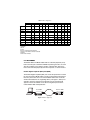
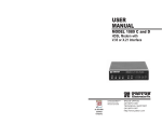
1
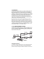
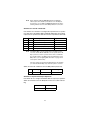
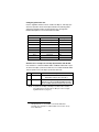
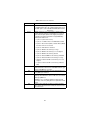
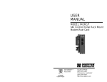
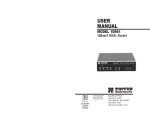
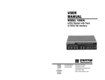
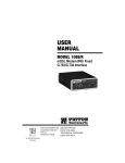
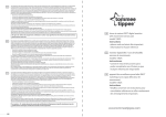
USER
MANUAL
MODEL 1082/I and
1082/144/I
iDSL Modem with
10Base- T Interface
Part# 07M1082/I-B
Doc# 033181UB
Revised 7/13/01
CERTIFIED
An ISO-9001
Certified
Company
SALES OFFICE
(301) 975-1000
TECHNICAL SUPPORT
(301) 975-1007
TABLE OF CONTENTS
1.0
1.1
1.2
1.3
Warranty Information .................................................................. 4
FCC Information ........................................................................... 4
CE Notice...................................................................................... 4
Service.......................................................................................... 5
2.0
2.1
2.2
2.3
General Information..................................................................... 6
Features........................................................................................ 6
Description.................................................................................... 7
1082 SNMP Management Solutions............................................. 7
HTTP/HTML Management ........................................................... 7
3.0
3.1
PPP Operational Background..................................................... 8
Applications .................................................................................. 8
4.0
4.1
Configuration ............................................................................. 11
Configuring the Hardware DIP Switches .................................... 11
Configuring DIP Switch S1 ......................................................... 12
Switches S1-1 and S1-2: Data Rate........................................... 13
Switch S1-5: Asynchronous/Sync Operation.............................. 13
Switches S1-6 and S1-7: System Clock Mode ........................... 14
Switch S1-8: Response to RDL Request.................................... 14
Configuring DIP switch “S2” ....................................................... 15
Switches S2-1: 19.2 kbps or 144* kbps
Synchronous Rate Enable.......................................................... 15
Switch S2-2: Front Panel Switch Disable ................................... 16
Switches S2-3, S2-6, S2-7 and S2-8: Reserved ........................ 16
5.0
5.1
5.2
5.3
5.4
Installation.................................................................................. 17
Connecting DSL Interface........................................................... 17
Connecting 10Base-T Ethernet Port to PC (DTE) ...................... 18
Connecting 10Base-T Ethernet Port to Hub (DCE) .................... 18
Power Connection ...................................................................... 19
Universal AC Power (100–240VAC)........................................... 19
DC Power ................................................................................... 20
6.0
6.1
6.2
6.3
Operation.................................................................................... 21
Power-up .................................................................................... 21
LED Status Monitors................................................................... 21
Test Modes ................................................................................. 23
Remote Digital Loopback (RDL)/V.52 (BER).............................. 23
A
A.1
A.2
A.3
A.4
A.5
A.6
A.7
1082/I Specifications ................................................................. 25
Transmission Format ...................................................................25
Transmission Line ........................................................................25
Clocking .......................................................................................25
Distance .......................................................................................25
Data Rates ...................................................................................25
Diagnostics ..................................................................................25
LED Status Indicators ..................................................................25
2
A.8
A.9
A.10
A.11
A.12
A.13
A.14
Connectors ..................................................................................25
Power ...........................................................................................25
Temperature Range .....................................................................26
Altitude .........................................................................................26
Humidity .......................................................................................26
Dimensions ..................................................................................26
Weight ..........................................................................................26
B
Model 1082/I Factory Replacement Parts
and Accessories ........................................................................ 27
3
1.0 WARRANTY INFORMATION
Patton Electronics warrants all Model 1082/I and Model 1082/144/I
components to be free from defects, and will—at our option—repair or
replace the product should it fail within one year from the first date of
shipment.
This warranty is limited to defects in workmanship or materials, and does
not cover customer damage, abuse or unauthorized modification. If this
product fails or does not perform as warranted, your sole recourse shall
be repair or replacement as described above. Under no condition shall
Patton Electronics be liable for any damages incurred by the use of this
product. These damages include, but are not limited to, the following: lost
profits, lost savings and incidental or consequential damages arising
from the use of or inability to use this product. Patton Electronics specifically disclaims all other warranties, expressed or implied, and the
installation or use of this product shall be deemed an acceptance of
these terms by the user.
1.1 FCC INFORMATION
This equipment has been tested and found to comply with the limits for a
Class A digital device, pursuant to Part 15 of the FCC Rules. These limits
are designed to provide reasonable protection against harmful interference when the equipment is operated in a commercial environment. This
equipment generates, uses, and can radiate radio frequency energy and,
if not installed and used in accordance with the instruction manual, may
cause harmful interference to radio communications. Operation of this
equipment in a residential area is likely to cause harmful interference in
which case the user will be required to correct the interference at his own
expense. If this equipment does cause harmful interference to radio or
television reception, which can be determined by turning the equipment
off and on, the user is encouraged to try to correct the interference by
one or more of the following measures:
• Reorient or relocate the receiving antenna
• Increase the separation between the equipment and receiver
• Connect the equipment into an outlet on a circuit different from that to
which the receiver is connected
1.2 CE NOTICE
The CE symbol on your Patton Electronics equipment indicates that it is in
compliance with the Electromagnetic Compatibility (EMC) directive and
the Low Voltage Directive (LVD) of the Union European (EU). A Certificate
of Compliance is available by contacting Patton Technical Support.
4
1.3 SERVICE
All warranty and non-warranty repairs must be returned freight prepaid
and insured to Patton Electronics. All returns must have a Return Materials Authorization number on the outside of the shipping container. This
number may be obtained from Patton Electronics Technical Service at:
Tel: (301) 975-1007
E-mail: [email protected]
URL: www.patton.com
Note
Packages received without an RMA number will not be
accepted.
Patton Electronics’ technical staff is also available to answer any questions that might arise concerning the installation or use of your
Model 1082/I or Model 1082/144/I. Technical Service hours: 8AM to 5PM
EST, Monday through Friday.
5
2.0 GENERAL INFORMATION
Thank you for your purchase of this Patton Electronics product. This
product has been thoroughly inspected and tested and is warranted for
One Year parts and labor. If any questions or problems arise during
installation or use of this product, please do not hesitate to contact
Patton Electronics Technical Support at (301) 975-1007.
2.1 FEATURES
• Provides MAC Level Data Link (Layer 2) connection between two
peered 10Base-T Ethernet LANs
• Operates transparently to higher level protocols such as TCP/IP, DECnet, NETBIOS and IPX
• PPP (Point to Point Protocol, RFC 1661) with Bridge Control Protocol
(RFC 1638)
• Automatically learns, loads and removes MAC addresses
• Point-to-point distances up to 5 miles (all data rates) on 24 AWG
twisted pair
• HTTP/SNMP Manageable as CP (Customer Premises) Unit with
1092ARC CO (Central Office) Rack Card and 1001MC management card
• Internal or receive recovered clocking between units
• LED indicators for 10Base-T Link, DSL Link, Status, No Signal, Error
and Test Mode
• Remote digital loopback, local line loopback diagnostic modes
• Synchronous data rates: 19.2, 32, 56, 64, 128, and 144 kbps
Note
144 kbps data rate is only available on the Model 1082/144/I.
19.2 kbps rate is available on all Model 1082 series modems
except for the 1082/144/I.
• Full duplex operation over a single twisted pair (2-wires)
• Multi-Rate Symmetric DSL
• Compatible with the popular Patton Model 1092A
• Universal power supply (90–260VAC) or DC power supply (-48VDC)
• Small, Convienent Desktop Unit
• CE Marked
6
2.2 DESCRIPTION
The Model 1082/I and Model 1082/144/I are Multi Rate iDSL Modems that
provide seamless MAC Layer connectivity between 2 peered 10Base-T
LANs. Now, Enterprise users no longer need to hassle with a bridge and a
CSU/DSU or recurring leased line costs. The 1082 allows users to add additional nodes to a LAN that has reached its maximum distance limits or separate high traffic areas of a LAN. The 1082 connects peered LANs and
automatically forwards and receives LAN broadcasts, multi-casts and
frames across a 2-wire DSL span. The Model 1082/I and Model 1082/144/I
support PPP (RFC 1s661) and BCP (RFC 1638).
Both 1082 modems’ features include loopback diagnostics, inband
SNMP/HTTP remote management capabilities using NetLink Plug-andPlay and externally accessible configuration switches. As a symmetric
DSL modem, the1082 offers the same data rates in both directions over
a single pair of regular telephone lines using 2BIQ modulation. The 1082
connects to the DSL line via an RJ-45 jack, and is powered by a universal (90–260VAC) supply or a DC supply (-48VDC).
2.3 1082 SNMP MANAGEMENT SOLUTIONS
The Model 1082/I and Model 1082/144/I are SNMP manageable when connected to a rack-mounted Model 1092ARC (see Figure 1). SNMP management is enabled through a 1001MC rack management card located in the
Patton Electronics Rack System.
Model 1082
10Base-T
connection
to 1001MC
2B1Q
connections to
remote 1082s
Management
Station
Model 1082
Rack-mounted
1092ARCs
Figure 1. Typical application
HTTP/HTML Management
The 1001MC maintains HTML pages that can be viewed through a Web
browser. You can display remote statistics and configure Model 1082
parameters simply by entering the 1001MC’s IP address into the browser.
7
3.0 PPP OPERATIONAL BACKGROUND
PPP is a protocol used for multi-plexed transport over a point-to-point
link. PPP operates on all full duplex media, and is a symmetric peer-topeer protocol, which can be broken into three main components:
• A standard method to encapsulate datagrams over serial links
• A Link Control Protocol (LCP) to establish, configure, and test the
data-link connection
• A family of Network Control Protocols (NCPs) to establish and configure different network layer protocols
In order to establish communications over a point-to-point link, each end
of the PPP link must first announce its capabilities and agree on the
parameters of the link’s operation. This exchange is facilitated through
LCP Configure-Request packets.
Once the link has been established and optional facilities have been
negotiated, PPP will attempt to establish a network protocol. PPP will
use Network Control Protocol (NCP) to choose and configure one or
more network layer protocols. Once each of the network layer protocols
have been configured, datagrams from the established network layer
protocol can be sent over the link. The link will remain configured for
these communications until explicit LCP or NCP packets close the link
down, or until some external event occurs.
The PPP Bridging Control Protocol (BCP), defined in RFC 1638, configures and enables/disables the bridge protocol on both ends of the pointto-point link. BCP uses the same packet exchange mechanism as the
Link Control Protocol (LCP). BCP is a Network Control Protocol of PPP,
bridge packets may not be exchanged until PPP has reached the network layer protocol phase.
3.1 APPLICATIONS
In situations where a routed network requires connectivity to a remote Ethernet network, the interface on a router can be configured as a PPP IP Half
Bridge. The serial line to the remote bridge functions as a Virtual Ethernet
interface, effectively extending the routers serial port connection to the
remote network. The bridge device sends bridge packets (BPDU’s) to the
router's serial interface. The router will receive the layer three address information and will forward these packets based on its IP address.
8
Patton 1082/C
connected to a router
Patton
1082/I
Bridge
Ethernet LAN
PEC device with
serial interface
Figure 2. Cisco router with serial interface, configured as PPP Half-Bridge
Figure 2 shows a typical Cisco router with a serial interface configured
as a PPP Half Bridge. The router serial interface uses a remote device
that supports PPP bridging to function as a node on the remote Ethernet
network. The serial interface on the Cisco will have an IP address on the
same Ethernet subnet as the bridge.
For example, the customer site is assigned the addresses 192.168.1.0/
24 through 192.168.1.1/24. The address 192.168.1.1/24 is also the
default gateway for the remote network. The above settings remove any
routing/forwarding intelligence from the CPE. The associated Cisco configuration will set serial interface (s0) to accommodate half bridging for
the above example.
Authentication is optional under PPP. In a point-to-point leased-line link,
incoming customer facilities are usually fixed in nature, therefore authentication is generally not required. If the foreign device requires authentication via PAP or CHAP, the PPP software will respond with default PeerID consisting of the units Ethernet MAC address and a password which
consists of the unit’s Ethernet MAC address.
Some networking systems do not define network numbers in packets
sent out over a network. If a packet does not have a specific destination
network number, a router will assume that the packet is set up for the
local segment and will not forward it to any other sub-network. However,
in cases where two devices need to communicate over the wide-area,
bridging can be used to transport non-routable protocols.
9
Figure 3. Transparent bridging between two routers over a serial interface
Figure 3 illustrates transparent bridging between two routers over a
serial interface (s0). Bridging will occur between the two Ethernet interfaces on router A (e0 and e1) and the two Ethernet interfaces on router B
(e0 and e1).
10
4.0 CONFIGURATION
The Model 1082/I and Model 1082/144/I each are equipped with 16 DIP
switches that enable configuration of the unit for a wide variety of applications. This section describes switch locations and explains the different
configurations.
4.1 CONFIGURING THE HARDWARE DIP SWITCHES
Using a small flat-tip screwdriver, remove the protective cover located on
the underside of the Model 1092 (see Figure 4).
/G
l1
03
de
G.7s NS
tu
Link
Sta
BT
L 10
DS
Mo
19
4E
Sin
gle
od
tM
es M
4T T
.70 ER
Mo
de
Fib
51
1E
es
5
D
N
1/R
51
em
od
4L M
.7S0
/GiD
a0s3tT
0B.7
BL
d1G
/R
uak
1E
Qin
- tL
51 al
eNr e
11 orm L
Figure 4. Removing the cover to access DIP switches S1 and S2
11
S1
S2
S2
ON
ON
1 2 3 4 5 6 7 8
1 2 3 4 5 6 7 8
S1
S1
Switch toggle
ON
1
2
3
4
5
6
7
8
Push toggle up ON
for ON position
1 2 3 4 5 6 7 8
1 2
S1
Push toggle
down for
OFF position
ON
Figure 5. DIP switches S2 and S2
Figure 5 shows the orientation of the DIP switches in the “ON” and “OFF”
positions.
Configuring DIP Switch S1
DIP switch S1 is where you configure the data rate, asynchronous or
synchronous data format, transmit clock source, and response to RDL
request. The following table summarizes default positions of DIP
switches S1-1 through S1-8. Detailed descriptions of each switch follow
the table.
Position
S1 Summary Table
Function
S1-1
Data Rate
On
S1-2
Data Rate
Off
S1-3
Reserved
On
Factory Default
S1-4
Reserved
On
S1-5
Async/Sync Data Format
Off
S1-6
Tx Clock Source
On
S1-7
Tx Clock Source
On
S1-8
Response to RDL Request
On
12
}
64K Sync
Async/Sync
}
Internal Clock
Enable
Note
When setting the 1082 for SNMP Management, the DTE rate
switches (S1-1,S1-2, and S2-1) must be also set to the ON position. Therefore, to set a 1082 unit SNMP Mangagement mode, the
following switches have to be at the ON position, S1-1, S1-2, S2-1.
Switches S1-1 and S1-2: Data Rate
Use switches S1-1 and S1-2 to configure the asynchronous or synchronous data rate of the Model 1082/I and Model 1082/144/I. Each setting
represents one synchronous data rate and one asynchronous data rate.
S1-1
S1-2
Sync Data Rate
Async. Data Rate
On
Off
On
Off
Off
On
On
Off
Off
Off
32 kbps
56 kbps
64 kbps
128 kbps (see note)
144 kbps or 19.2 kbps (see note)
Reserved
Reserved
Reserved
0–38.4 kbps
Reserved
Note
The Model 1082/I can also operate at the 19.2 kbps synchronous rate, and the Model 1092/144/I can also operate at the 144
kbps synchronous rate. To operate at these rates, set Switches
S1-1 and S1-2 both to the OFF position and Switch S2-1 to the
ON position (see “Configuring DIP switch “S2”” on page 152 for
a description of Switch S2-1).
If the S2-1 switch is positioned in the OFF position, the 128 kbps
sync data rate/0–38.4 kbps async data rate option is selected.
Switch S1-3 and S1-4: Must be set to the ON position (Reserved).
S1-3
Setting
S1-4
Setting
On
Reserved
On
Reserved
Switch S1-5: Asynchronous/Sync Operation
Use Switch S1-5 to configure the Model 1082 for async/sync operation.
Switch S1-5 must be set in the Off position. There is no other valid setting.
S1-5
Setting
Off
Async/Sync
13
Switches S1-6 and S1-7: System Clock Mode
Use Switches S1-6 and S1-7 to configure the 1082/I or Model 1082/144/
I for internal, or receive recover clock mode.
S1-6
S1-7
Clock Mode
Description
On
On
On
Off
Internal
Receive Recover
System clock generated internally
System clock derived from the
received line signal
Off
Off
Hardware Reset
Important
A pair of Model 1082/Is communicate synchronously
across the twisted pair line connection. Therefore, you
must set these switches whether your application is
async or sync. For Sync or Async applications, please
configure one Model 1082/I for internal clock mode and
the other Model 1082/I for receive recover clock mode.
Switch S1-8: Response to RDL Request
Use Switch S1-8 to allow Model 1082/I and Model 1082/144/I to enter the
Remote Digital Loopback diagnostic test when requested to do so by the
far end Model 1082/I and Model 1082/144/I. For example, when switch S18 is set to “ON”, it will enter RDL mode (See section 6.3, “Test Modes” on
page 23) when requested to do so by the remote Model 1082/I and Model
1082/144/I.
Note
S1-8
Setting
On
Off
Response to RDL Request Enabled
Response to RDL Request Disabled
The Remote Digital Loopback (RDL) will not work for 144 kbps.
You must first set the units to 128 kbps or slower to use the RDL.
14
Configuring DIP switch “S2”
Use the eight DIP switches in S2 to enable 19.2 kbps or 144* kbps synchronous operation and set the loopback modes. The following table
summarizes default positions of DIP switches S2-1 through S2-8.
Detailed descriptions of each switch follow the table.
Position
S2 Summary Table
Function
S2-1
19.2 or 144* kbps Enable
Off
S2-2
Front Panel Switch Disabl e
Off
S2-3
Reserved
Off
S2-4
Reserved
Off
S2-5
Reserved
Off
S2-6
Reserved
On
S2-7
Reserved
Off
S2-8
Reserved
Off
Factory Default
Switches S2-1: 19.2 kbps or 144* kbps Synchronous Rate Enable
Use switch S2-1 to allow the Model 1082/I and Model 1082/144/I to operate at the 19.2 kbps synchronous data rate, or to enable the Model 1082/
144/I to operate at the 144* kbps synchronous data rate.
S2-1
Activation
Description
Off
Disabled
On
Enabled
Synchronous data rate is 32–128 kbps as
defined by switches S1-1 and S1-2
Model 1082/I operates at synchronous 19.2 kbps
data rate (see note). The Model 1082/144/I operates at 144 kbps synchronous data rate (see note)
Note
*
To operate at 19.2 kbps or 144 kbps, set switches S1-1 and S1-2
to the OFF position and switch S2-1 to ON (see section “Configuring DIP Switch S1” on page 12).
144 kbps data rate is only available on the Model 1082/144/I.
19.2 kbps rate is available on all Model 1082 series modems except
for the 1082/144/I.
15
Switch S2-2: Front Panel Switch Disable
Use switch S2-2 to enable or disable the front panel toggle switches.
S2-2
Setting
On
Off
Disable the front panel switches
Enable the front panel switches
Switches S2-3, S2-6, S2-7 and S2-8: Reserved
16
5.0 INSTALLATION
When the Model 1082 has been properly configured, it may be connected to the DSL twisted pair interface, the 10Base-T Ethernet Interface, and the power source. This section describes these connections.
Interface connector
ON
Made in the USA
|
Power
OFF O
DSL interface
Interface
DSL
Power input
connector
Mo
G.7
Po de
wel 11
r 9
4E
03
Sin
/G
gle
.70
4T
es
Mo
de
5M1
tM
od
a1dE
e in
es
DSFib
L er -
the
US
A
Qu
ad
G.7
03
/G.7
04
InteMo
rfadem
ce
Figure 6. Model 1082/I or Model 1082/144/I rear view
5.1 CONNECTING DSL INTERFACE
The Model 1082 supports communication between 10Base-T Hubs or
Workstations at distances to 5 miles (8 km) over 24 AWG (.5mm) twisted
pair wire. There are two requirements for installing the Model 1082:
• These units operate as a pair. Both units at the end of the twisted pair
DSL span must be set for the same DTE rate.
• To function properly, the Model 1082 needs one twisted pair of metallic
wire. This twisted pair must be unconditioned, dry, metallic wire,
between 19 (.9mm) and 26 AWG (.4mm) (the higher number gauges
will limit distance). Standard dial-up telephone circuits, or leased circuits that run through signal equalization equipment, or standard, flat
modular telephone type cable, are not acceptable.
17
The RJ-45 connector on the Model 1082’s twisted pair interface is polarity insensitive and is wired for a two-wire interface. The signal/pin relationships are shown in Figure 7 below.
Figure 7. Model 1082/I twisted pair line interface
5.2 CONNECTING 10BASE-T ETHERNET PORT TO PC (DTE)
The 10Base-T interface is configured as DTE (Data Terminal Equipment). If the Model 1088 is to to connect to another DTE device such as
a 10Base-T network interface card, construct a 10Base-T crossover
cable and connect the wires as shown in Figure 8.
10Base-T Port
RJ-45 Pin No.
1 (TD+)
2 (TD-)
3 (RD+)
6 (RD-)
10Base-T DTE
RJ-45 Pin No.
1 (TD+)
2 (TD-)
3 (RD+)
6 (RD-)
Figure 8. Connecting 10Base-T Ethernet port to PC
5.3 CONNECTING 10BASE-T ETHERNET PORT TO HUB (DCE)
The 10Base-T interface is configured as DTE (Data Terminal Equipment), just like a 10Base-T network interface card in a PC. Therefore, it
“expects” to connect to a 10Base-T Hub using a straight-through RJ-45
cable. Figure 9 shows how to construct a cable to connect the 10Base-T
interface to a 10Base-T Hub.
10Base-T Port
RJ-45 Pin No.
1 (TD+)
2 (TD-)
10Base-T Hub
RJ-45 Pin No.
1 (TD+)
2 (TD-)
3 (RD+)
6 (RD-)
3 (RD+)
6 (RD-)
Figure 9. Connecting the 10Base-T interface to a 10Base-T Hub
18
5.4 POWER CONNECTION
Universal AC Power (100–240VAC)
The Model 1082/I uses a 5VDC, 2A universal input 100–240VAC, power
supply (center pin is +5V). The universal input power supply has a male
IEC-320 power entry connector. This power supply connects to the
Model 1082/I by means of a barrel jack on the rear panel. Many international power cords are available for the universal power supply. Please
refer to Appendix B for country-specific power cords.
The Model 1082/I powers up as soon as it is plugged into an AC outlet.
The Model 1082/I does not have a power switch.
19
DC Power
The DC adapter supplied with the DC version of the model 1082/I plugs in a
DC source (nominal 48VDC) and plugs into the barrel power supply jack on
the rear of the 1082/I. Refer to Figure 10 below to make the proper connection.
To Power
Supply Jack
-Vin
To -48VDC
Source
+Vin
Figure 10. Power adapter
There are no user-serviceable parts in the power supply
section of the Model 1082/I. Contact Patton Electronics
Technical support at +1 (301) 975-1007, via our web site
at www.patton.com, or by E-mail at
[email protected], for more information.
WARNING
20
6.0 OPERATION
When the Model 1082/I and Model 1082/144/I have been properly configured and installed, it should operate transparently. This sections describes
power-up, LED status monitors, and the built-in loopback test modes.
6.1 POWER-UP
Before applying power to the Model 1082/I or Model 1082/144/I, please
read section 5.4, “Power Connection” on page 19 and ensure that the
unit is connected to the appropriate power source.
6.2 LED STATUS MONITORS
The Model 1082/I and Model 1082/144/I feature six front panel LEDs that
monitor connections on the DSL and 10Base-T links, signaling, error and
test modes. (See Figure 11 for front panel location of each LED).
Descriptions of each LED follow in Table 1 on page 22.
NetLink™ 10Base-T iDSL Model
Link
DSL
10BT
DSL
NS
ER
TM
NS
10BT
ER
511E/RDL
Normal
511/RDL
TM Loopback
switch
Figure 11. Model 1082/I or 1082/144/I front panel LED locations
21
Table 1: LED status monitor indications
LED
Description
DSL Link
(Active Green) Solid green (On) indicates that the end to
end DSL Framer Link is up, signifying that the link across
the DSL span is active. The DSL Link LED is Off when the
link is down.
Blinks yellow from one to eleven times to indicate system
status. Each pulse pattern is separated by a 2 second “off”
period. Greater pulse patterns have higher priority (buffer
saturation has greater priority than an empty MAC table).
Valid system statuses are:
Status
• 1 pulse—system status is okay
• 2 pulses—no MAC entries in the MAC Address Table
• 3 pulses—Clear to Send (CTS) or Carrier Detect (DCD)
from base unit are not asserted
•
•
•
•
•
•
•
4 pulses—IM1/I buffer is saturated
5 pulses—WAN receive frame(s) too large
6 pulses—WAN receive frame(s) not octet aligned
7 pulses—WAN receive frame(s) aborted
8 pulses—Detected WAN receive frame(s) with CRC
9 pulses—Detected LAN receive frame(s) too large
10 pulses—Detected LAN receive frame(s) not octet
aligned
• 11 pulses—Detected LAN receive frame(s) with bad
10BT Link
NS
ER
TM
CRC
(Active green) Solid green indicates that the 10Base-T
Ethernet interface has detected a valid SQE heartbeat, signifying a valid 10Base-T connection
(Active red) Solid red indicates that the Digital Signal Processors (DSPs) are not linked
(Active red) Flashing red indicates CRC errors on DSL
(framer) side if DSL Link is active or if bit errors are received
during loop/BER test
ER flashes once, to indicate a CRC error (during normal
operation) or bit errors (during Remote Loopback 511/511E
tests)
(Active yellow) Solid yellow indicates an Active Test Mode.
The unit may be placed in test mode by the local user or by
the remote user.
22
Table 2: LED configurations
LOCAL
Power ON
REMOTE
10Base-T
DSL
Status
NS
ER
TM
10Base-T
DSL
Status
NS
ER
TM
G*
off
F
on
off
off
G*
off
F
O
N
off
off
DSL Link
G*
G
F
off
off
off
G*
off
F
off
off
off
Link Brk
G*
off
F
off
off
off
G*
off
F
off
off
off
Brk+ 10s
G*
off
F
ON
off
off
G*
off
F
O
N
off
off
RDL
G*
G
F
off
off
ON
G*
off
F
off
off
ON
RDL+511
G*
off
F
off
off
ON
G*
off
F
off
off
ON
Mark
G*
G
F
off
off
off
G*
G
F
off
off
off
Space
G*
G
F
off
off
off
G*
G
F
off
off
off
Data
G*
G
F
off
off
off
G*
G
F
off
off
off
With DTE Connected
With DTE Connected
G=GREEN
O=ORANGE
ON= ON
off= OFF
Brk+10s = 10 Seconds following Link Break
G*=Green if a valid 10Base-T connection is detected.
F=Flashing
Link Brk = DSL Link Broken
6.3 TEST MODES
The Model 1082/I and Model 1082/144/I has a built-in proprietary loopback test mode, plus a built-in V.52 BER test pattern generator, for evaluating the condition of the modems and the communication link. These
tests can be activated physically from the front panel, or via the interface.
Remote Digital Loopback (RDL)/V.52 (BER)
The Remote Digital Loopback (RDL) test checks the performance of both
the local and remote Model 1082s, and the communication link between
them. Any characters sent to the remote Model 1082 in this test mode
will be returned back to the originating device (see Figure 7, below). For
example, characters typed on the keyboard of the local terminal will
appear on the local terminal screen after having been passed to the
remote Model 1082 and looped back.
Local 1082
Remote 1082
RDL initiated
Figure 12. Remote digital loop
23
Do not send a 511 test pattern from the test equipment
when you connect external test equipment to the 1082.
Important
Activating RDL can be done in two ways:
1. Move the front panel toggle switch to appropriate position.
2. Set remote loopback from SNMP screen (when used with 1092ARC
Rack Card)
Note
Remote loopback cannot be activated until approximately 45
seconds after the two modems have linked to each other.
Note
The Remote Digital Loopback (RDL) will not work for 144 kbps.
You must first set the units to 128 kbps or slower to use the RDL.
To use the V.52 BER tests with the Remote Digital Loopback tests, do the
following:
1. Locate the 511/RDL toggle switch on the front panel of the 1082/I
and move it DOWN. This initiates the RDL and sends a 511 pattern
into the loop. If any errors are present, the local modem’s red “ER”
LED will blink continually.
2. If the above test indicates no errors are present, move the V.52 toggle switch UP, activating the 511E/RDL test with errors present. If
the test is working properly, the local modem's red “ER” LED will
blink approximately once per second. A successful 511E/RDL test
will confirm that the link is in place, and that the Model 1082’s built-in
“511” generator and detector are working properly.
24
APPENDIX A
1082/I Specifications
A.1 TRANSMISSION FORMAT
Synchronous or asynchronous
A.2 TRANSMISSION LINE
Single unconditioned twisted pair
A.3 CLOCKING
Internal or receive loopback
A.4 DISTANCE
2-Wire Distance Table in miles (km)
AWG Wire Gauge (mm)
Data Rate
All rates
19 (.9)
22 (.6)
24 (.5)
6 (.4)
10.8 (17.2)
7.2 (11.5)
5.0 (8.0)
3.4 (5.5)
A.5 DATA RATES
Synchronous 19.2, 32, 56, 64, and 128 kbps, (and 144 kbps on 1082/144
only); Asynchronous 0–38.4 kbps
A.6 DIAGNOSTICS
V.52 compliant bit error rate pattern (511/511E pattern) generator and
detector with error injection mode; Local Line Loopback and Reomote Digital Loopback, activated by front panel switches or via serial interface.
A.7 LED STATUS INDICATORS
DSL, 10Base-T, Status, NS (no signal), ER (error) and TM (test Mode)
A.8 CONNECTORS
RJ-45 on line side; shielded RJ-45 on Ethernet port
A.9 POWER
100–253 VAC, 50–60 Hz (universal input option); 48 VDC (optional),
5 watts
25
A.10 TEMPERATURE RANGE
32–122°F (0–50°C)
A.11 ALTITUDE
0–15,000 feet (0–4,572 meters)
A.12 HUMIDITY
5–95% non-condensing
A.13 DIMENSIONS
4.125W x 1.625H x 6.0D in. (10.5W x 4.1W x 15.2D cm)
A.14 WEIGHT
2.01 lbs. (1.0 kg)
26
APPENDIX B
MODEL 1082/I FACTORY REPLACEMENT PARTS AND ACCESSORIES
Model #
Description
1082/I
1082/144/I
10Base-T, DSL Modem
10Base-T DSL modem with maximum data rate of 144 kbps
48V-PSM
08055DCUI
DC Power Supply Module
100-240VAC (+5V ±5% reg. DC/2A) Universal Input Adapter
0805EUR
0805UK
0805US
0805AUS
0805DEN
0805FR
0805IN
0805IS
0805JAP
0805SW
European Power Cord CEE 7 (“A”)
United Kingdom Power Cord (“D”)
American Power Cord (“K”)
Australia/New Zealand Power Cord (“C”)
Denmark Power Cord (“E”)
France/Belgium Power Cord (“F”)
India Power Cord (“G”)
Israel Power Cord (“H”)
Japan Power Cord (“J”)
Switzerland Power Cord (“L”)
07M1082
User Manual
27
Notes
_________________________________________________________
_________________________________________________________
_________________________________________________________
_________________________________________________________
_________________________________________________________
_________________________________________________________
_________________________________________________________
_________________________________________________________
_________________________________________________________
_________________________________________________________
_________________________________________________________
_________________________________________________________
_________________________________________________________
_________________________________________________________
_________________________________________________________
_________________________________________________________
_________________________________________________________
_________________________________________________________
_________________________________________________________
_________________________________________________________
_________________________________________________________
Copyright © 1998, 2001
Patton Electronics Company
All Rights Reserved.
28