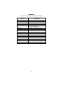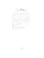
1
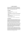
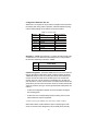
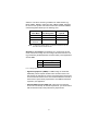
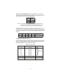
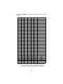
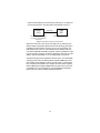
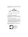
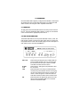
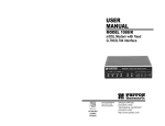
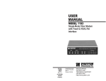
USER
MANUAL
MODEL 1088/K
mDSL Modem With Fixed
G.703/G.704 Interface
Part# 07M1088K-UM
Doc# 03314U2-001
Rev. E
Revised 11/6/06
An ISO-9001Certified
Company
SALES OFFICE
(301) 975-1000
TECHNICAL SUPPORT
(301) 975-1007
CONTENTS
1.0
1.1
1.2
1.3
Warranty Information .................................................................
Radio and TV Interference............................................................
CE Notice......................................................................................
Service..........................................................................................
2.0
2.1
2.2
General Information.................................................................... 6
Features........................................................................................ 6
Description.................................................................................... 6
3.0
3.1
Installation................................................................................... 7
Configuring the Hardware DIP Switches ...................................... 7
Configuration DIP Switch Set “S1” ............................................... 8
Switch S1-1: CO/CP ............................................................. 8
CO/CP Configuration ............................................................. 8
Switch S1-2: Line Coding ...................................................... 9
Switch S1-3: CRC-4 Multiframe .......................................... 10
Switches S1-4, S1-5, S1-6, S1-7 and S1-8: Reserved ....... 10
Configuration DIP Switch Set “S2” ............................................. 10
Switch S2-1: DTE Rate ....................................................... 11
Switch S2-7: Reset Software Defaults ................................ 12
Switch S2-8: Transmit Data (TD) Sampling Point ............... 12
NetLink Plug-and-Play ................................................................ 12
3.2
4.0
4.1
4.2
4.3
4.4
5.0
5.1
5.2
5.3
5.4
4
4
4
5
Installation.................................................................................
Connect G.703 Network .............................................................
Jumper Configuration .................................................................
Connect Twisted Pair (120 ohm) to G.703 Network ...................
Connect Dual Coaxial Cable (75 ohm) to G.703 Network ..........
Connect Twisted-Pair DSL Interface ..........................................
Power Connection ......................................................................
Universal AC Power (100–240 VAC)..........................................
120 VAC Power (US)..................................................................
230 VAC Power (International)...................................................
DC Power ...................................................................................
14
14
14
15
15
16
17
17
17
17
17
Operation...................................................................................
Power-up ....................................................................................
LED Status Monitors...................................................................
Test MODES...............................................................................
Overview.....................................................................................
Loops and Patterns.....................................................................
Using the V.52 (BER) Test Pattern Generator ...........................
18
18
18
19
19
21
25
A
Specifications ........................................................................... 26
A.1 Clocking Modes .......................................................................... 26
A.2 DTE Rate ..................................................................................... 26
2
A.3
A.4
A.5
A.6
A.7
A.8
A.9
A.10
A.11
A.12
A.13
A.14
A.15
A.16
Diagnostics ................................................................................. 26
LED Status .................................................................................. 26
Configuration .............................................................................. 26
Power .......................................................................................... 26
Compliance ................................................................................. 26
Line Coding ................................................................................ 27
Line Rates (DSL line) .................................................................. 27
mDSL Physical ............................................................................ 27
G.703/G.704 Specific ................................................................. 27
Line rate ...................................................................................... 27
Line coding ................................................................................. 27
Line Framing ............................................................................... 27
Isolation ....................................................................................... 27
Physical Connection ................................................................... 27
B
Factory Replacement Parts and Accessories........................ 28
C
Transmission Distance Chart .................................................. 29
D
Model 1088/K LED Descriptions.............................................. 30
3
1.0 WARRANTY INFORMATION
Patton Electronics warrants all Model 1088 components to be free from
defects, and will—at our option—repair or replace the product should it
fail within one year from the first date of shipment.
This warranty is limited to defects in workmanship or materials, and does
not cover customer damage, abuse or unauthorized modification. If this
product fails or does not perform as warranted, your sole recourse shall
be repair or replacement as described above. Under no condition shall
Patton Electronics be liable for any damages incurred by the use of this
product. These damages include, but are not limited to, the following:
lost profits, lost savings and incidental or consequential damages arising
from the use of or inability to use this product. Patton Electronics specifically disclaims all other warranties, expressed or implied, and the installation or use of this product shall be deemed an acceptance of these
terms by the user
Note
Conformity documents of all Patton products can be viewed
online at www.patton.com under the appropriate product page.
1.1 RADIO AND TV INTERFERENCE
The Model 1088 generates and uses radio frequency energy, and if not
installed and used properly—that is, in strict accordance with the manufacturer's instructions—may cause interference to radio and television
reception. The Model 1088 has been tested and found to comply with the
limits for a Class A computing device in accordance with the specifications in Subpart J of Part 15 of FCC rules, which are designed to provide
reasonable protection from such interference in a commercial installation. However, there is no guarantee that interference will not occur in a
particular installation. If the Model 1088 does cause interference to radio
or television reception, which can be determined by disconnecting the
unit, the user is encouraged to try to correct the interference by one or
more of the following measures: moving the computing equipment away
from the receiver, re-orienting the receiving antenna and/or plugging the
receiving equipment into a different AC outlet (such that the computing
equipment and receiver are on different branches).
1.2 CE NOTICE
The CE symbol on your Patton Electronics equipment indicates that it is
in compliance with the Electromagnetic Compatibility (EMC) directive
and the Low Voltage Directive (LVD) of the European Union (EU). A Certificate of Compliance is available by contacting Technical Support.
4
1.3 SERVICE
All warranty and non-warranty repairs must be returned freight prepaid
and insured to Patton Electronics. All returns must have a Return Materials Authorization number on the outside of the shipping container. This
number may be obtained from Patton Electronics Technical Services at:
• Tel: +1 (301) 975-1007
• Email: [email protected]
• URL: http://www.patton.com
Note
Packages received without an RMA number will not be
accepted.
Note
The Model 1088 is flash upgradeable. Please refer to Patton
website, or contact Technical Support for the latest version of
the software.
5
2.0 GENERAL INFORMATION
Thank you for your purchase of this Patton Electronics product. This
product has been thoroughly inspected and tested and is warranted for
One Year parts and labor. If any questions or problems arise during
installation or use of this product, please do not hesitate to contact Patton Electronics Technical Support at (301) 975-1007.
2.1 FEATURES
• Multi-Rate Symmetric DSL
• Supports DTE Speeds from 64 kbps to 2.048 Mbps
• 2-wire Operation
• 120 ohm (RJ-48C) and 75 ohm (dual coax) G.703/G.704 terminations
• 2-Mbps G.703 Clear Channel (Unframed) or nx64 G.704 (Framed)
Operation
• SNMP Manageable as the CP (Customer Premises) modem when
connect to Model 1095RC
• Selectable AMI or HDB3 Line Coding
• LED indicators for DSL Link, E1/FE1 Link, LOS, TM, ER and NS
2.2 DESCRIPTION
The Patton Electronics mDSL Rocket offers the ability to extend G.703/
G.704 service over Multi-rate Symmetric Digital Subscriber Line technology. Multi-rate DSL offers the ability to deliver the maximum bit rate that a
twisted pair line can accommodate. Now, ISPs, CLECs and corporate
enterprises can terminate G.703/G.704 (E1) service and either extend
nx64 G.703/G.704 service or provide a remote serial connection to a
router or switch when paired with Model 1088/C (V.35) or 1088/D (X.21).
As Model 1088/K receives data from E1 line, it extracts the E1 clock, and
delivers smooth clock and data to the remote DSL modem over a two-wire
DSL span. In a network extension application, a remote 1088/K delivers
nx64kbps to 2 Mbps G.703 data and clocking to device with an E1 interface. In a network termination application, a remote Model 1088/C or
1088/D accepts this data and clock stream and provides nx64kbps data to
CPE with a V.35, or X.21 interface.
As a symmetric DSL NTU, Model 1088/K offers the same data rates in
both directions over a single pair of regular telephone lines using Carrierless Amplitude and Phase (CAP) modulation. Equipped with 75 ohm (dual
coax) and 120 ohm (RJ-48C), the Model 1088/K is easy to configure and
install. DSL line connection is via RJ-45 jack. Standard versions of Model
1088 are powered by a 100/230VAC (Universal) supply. A DC power supply option supports any DC input between 36–72VDC.
6
3.0 INSTALLATION
The Model 1088/K is equipped with two sets of eight DIP switches, which
allow configuration of the unit for a wide variety of applications. This section
describes switch locations and explains all possible configurations.
3.1 CONFIGURING THE HARDWARE DIP SWITCHES
The 16 external switches are grouped into two eight-switch sets, and are
externally accessible from the underside of the Model 1088/K (See
Figure 1).
Figure 1. Underside of Model 1088/K showing location of DIP switches
The two sets of DIP switches on the underside of the Model 1088/K will
be referred to as S1 and S2. As Figure 2 shows, the orientation of all DIP
switches is the same with respect to “ON” and “OFF” positions.
ON
OFF
Figure 2. Close-up of configuration switches (all sets are identical in appearance)
7
Configuration DIP Switch Set “S1”
Switches S1-1 through S1-8 may be used to configure CO/CP operation,
line framing and coding, CRC-4 operation, and DTE initiated loop diagnostics. Default settings of S1 switches are shown in Table 1.
Table 1: S1 Summary Table
Position
S1-1
S1-2
S1-3
S1-4
S1-5
S1-6
S1-7
S1-8
Function
CO/CP Setting
Line Coding
CRC-4 Enable
Reserved
Reserved
Reserved
Reserved
Reserved
Factory Default
On CP Mode
Off HDB3
Off Disabled
Off
On
Off
On
Off
Switch S1-1: CO/CP. Use Switch S1-1 configure the CO (located at the
Central Office or or G.703/G.704 demarcation point) or CP (located at
the Customer Premises) mode of the 1088/K.
S1-1
CO/CP Mode
Off
On
CO = located at the Central Office
CP = located at the Customer Premises
CO/CP Configuration. The Model 1088/K does not use clock mode settings as described in other Patton mDSL products. Instead, the Model
1088/K will always recover the clocking from the G.703/4 network and
use this clock to send data across the DSL span to the remote DSL
modem, which will use the incoming to send data out to G.703/4 network. Therefore, one unit must be set for CO mode (located at the G.703
demarcation), and the other unit must be set for CP mode (located at the
customer premises). This type of clocking method was employed for two
reasons:
• To allow two independent networks to use the modems as independent clocking paths.
• To allow the user to independently specify the timing source for the
network based on external equipment.
CO/CP and Using the 1088/K with other Patton mDSL modems
Other Patton mDSL modems allow the option of specifying the clock
mode, but not the CO/CP designation. This is already done internally
8
within the unit. When connecting a 1088/K to an mDSL modem (e.g.
Model 1088/C, 1088/D or 1095) other then a Model 1088/K, determine
the source of the system clock and then determine the Model 1088/Ks
CO/CP designation based upon the following chart.
MDSL Modem
Clock Mode
MDSL Modem
Unit Designation
1088/K setting
required
External
Internal
Receive
Recover
External
Internal
Receive Recover
CP
CP
CO
Note
In each DSL modem pairing, one unit must act as the CO unit,
the other must act as the CP unit.
Switch S1-2: Line Coding. Use Switch S1-2 to configure the G.703/
G.704 network line coding. The line coding must be the same line coding prescribed by the NAP (Network Access Provider). Most applications
will use HDB3
SW4
Line Framing & Coding
Off
On
HDB3
AMI
Line Coding Options:
• High Density Bipolar 3 (HDB3): In HDB3 coding, the transmitter
deliberately inserts a bipolar violation when excessive zeros in the
data stream are detected. The receiver recognizes these special violations and decodes them as zeros. This method enables the network to
meet minimum pulse density requirements. Use HDB3 unless AMI is
required in your application .
• Alternate Mark Inversion (AMI): AMI coding does not inherently
account for ones density. To meet this requirement, you should ensure
that the data inherently meets pulse density requirements.
9
Switch S1-3: CRC-4 Multiframe. CRC-4 Multiframe uses Time Slot
zero to carry CRC-4 information. When CRC-4 is enabled (ON), the unit
synchronizes to the CRC-4 multi-frame protocol.
Note
S1-3
Option
Off
On
Disabled
Enabled
When the DTE rate is set to 2048 Kbps, Model 1088/K transmits
user data on all 32 timeslots, ignoring framing information. In this
case, Switch S1-3 will need to be in the disabled (Off) position.
Switches S1-4, S1-5, S1-6, S1-7 and S1-8: Reserved. Switches S1-4,
S1-5, S1-6, S1-7, S1-8 are reserved for factory usage and must remain
in the default configuration, except when using the Netlink Plug-and-Play
feature.
S1-4
S1-5
S1-6
S1-7
S1-8
Default Setting
Off
On
Off
On
Off
Only Valid Setting
Configuration DIP Switch Set “S2”
Use the eight DIP Switches in Switch S2 to enable the DTE connection
rate. The following table summarizes default positions of DIP Switch S3.
Detailed descriptions of each switch follow Table 2.
Table 2: S2 Summary Table
Position
Function
Factory Default
S2-1
DTE Rate
Off
S2-2
DTE Rate
Off
S2-3
DTE Rate
On
S2-4
DTE Rate
On
S2-5
DTE Rate
On
S2-6
DTE Rate
Off
}
2048 kbps
S2-7
Reset Software Defaults
On
Normal Operation
S2-8
Transmit Data Sample Point
On
Normal Operation
10
Switch S2-1: DTE Rate. Use Switch S2-1 through S2-6 to set the DTE
bit rate.
S2-1
Off
On
Off
On
Off
On
Off
On
Off
On
Off
On
Off
On
Off
On
Off
On
Off
On
Off
On
Off
On
On
Off
On
Off
On
Off
On
Off
Note
S2-2
S2-3
S2-4
S2-5
S2-6
DTE Rate (kbps)
Off
On
On
Off
Off
On
On
Off
Off
On
On
Off
Off
On
On
Off
Off
On
On
Off
Off
On
On
Off
On
On
Off
Off
On
On
Off
Off
On
Off
Off
Off
Off
On
On
On
On
Off
Off
Off
Off
On
On
On
On
Off
Off
Off
Off
On
On
On
Off
Off
Off
Off
On
On
On
On
On
On
On
On
On
Off
Off
Off
Off
Off
Off
Off
Off
On
On
On
On
On
On
On
On
Off
Off
Off
Off
Off
Off
Off
On
On
On
On
On
On
On
On
On
On
On
On
On
On
On
On
On
Off
Off
Off
Off
Off
Off
Off
Off
Off
Off
Off
Off
Off
Off
Off
On
On
On
On
On
On
On
On
On
On
On
On
On
On
On
On
On
On
On
On
On
On
On
On
On
On
On
On
On
On
On
On
Off
Off
Off
Off
64
128
192
256
320
384
448
512
576
640
704
768
832
896
960
1024
1088
1152
1216
1280
1344
1408
1472
1536
1600
1664
1728
1792
1856
1920
1984
2048
Based on the DTE rate chosen, the Model 1088/K will automatically select the optimum line rate for the distance. This selection
is based on the lowest line rate that will support the DTE rate.
11
Switch S2-7: Reset Software Defaults. Switch S3-7 allows the user to
reset the software configured factory defaults. This will only be needed
when using the Model 1001MC to SNMP manage your units. For more
information, please refer to the Model 1001MC Operations Manual.
S3-7
Setting
On
Off
Normal Operation
Reset
Switch S2-8: Transmit Data (TD) Sampling Point. Switch 3-8 controls
the Transmit Data (TD) sampling point.
S3-8
Setting
Description
On
Normal
Off
Invert
TD sampled on the falling edge of the 1088 Transmit Clock (TC)
TD sampled on the rising edge of the 1088 Transmit
Clock.
3.2 NETLINK PLUG-AND-PLAY
The NetLink Plug-and-Play feature allows ISPs, carriers and PTTs to
quickly upgrade the link speed for a customer without requiring a visit to
re-configure the Customer Premise (CP) Model 1088. This feature also
allows service providers to set up all of the configurations at the Central
Office (on the rack cards) before installing the stand alone units, saving
time spent configuring or re-configuring DIP switches.
Note
NetLink Plug-and-Play is only available when using a rackmounted NetLink Model 1095RC as the CO unit.
The NetLink Plug-and-Play feature allows the user to configure the DTE
rate (bandwidth allocation, see Switches S2-1 through S2-6) of the CP
unit from the rack card at the Central Office (CO). The stand alone unit at
the Customer Premise (CP) site will automatically configure itself to the
DTE rate (Bandwidth Allocation) of the rack card. Other configuration
parameters remain in the default setting.
Follow the instructions below to activate NetLink Plug-and-Play between
CO (Model 1095RC and CP (Model 1088) units:
• Set the Model 1095RC (CO) to either Internal or External clocking
mode as defined by the application.
12
• Set the Model 1088 (CP) to “NetLink Plug-and-Play CP” by setting S1
and S2 DIP switches in the ON position as described in Figure 3.
1095RC
(CO)
DSL Span
1088
(CP)
DIP Switches all in ON position
DIP Switches or NMS configured
according to specific application
requirements
Figure 3. Typical NetLink Plug-and-Play Application
When the CO and CP units connect over DSL, the CP will enter a predefined default configuration (Receive Recovered Clocking). During the
negotiation process between the units, the CO unit will configure the
DTE rate/line rate on the CP unit as defined by the settings of the CO
unit. When additional bandwidth is required, only the configuration of the
CO unit should be changed. This feature gives ISPs, LECs and PTTs the
ability to provision bandwidth on an as needed basis to customers.
The NetLink Plug and Play application will also work in an HTTP/SNMP
managed system using the NetLink Model 1001MC SNMP agent card
with 1095RC cards installed in Patton’s 2U rack system. In this application, the system administrator can configure the entire rack through the
Network Management Station (NMS) before the stand alone (CP) units
are installed. For more information on the HTTP/SNMP management,
please refer to the Model 1001MC Operations Manual.
13
4.0 INSTALLATION
Once the Model 1088/K is properly configured, it is ready to connect to
the twisted pair interface, to the serial port, and to the power source. This
section describes how to make these connections.
4.1 CONNECT G.703 NETWORK
The Power, G.703/G.704 and DSL Line connections are located on the
rear panel of the Model 1088/K. Figure 4 shows the location of each of
these ports.
Power
G.703/G.704 Terminations
RX
DSL Line
TX
Figure 4. Model 1088/K Rear Panel
4.2 JUMPER CONFIGURATION
The Model 1088/K has four jumpers (two position headers): JP1, JP4,
JP5, and JP6. These jumpers are used to select input or output impedance matching between the module, external line, and to employ either
BNC or RJ-48C interface. Figure 5 (below) shows the top view of the
printed circuit board (PCB) and the location of the jumpers.
RX
TX
Figure 5. Top view of 1088/K, location of JP1, JP4, JP5, and JP6
14
The following is a description of the jumper settings with respect to the
rear panel connectors.
• For a 75-ohm connection (coax) insert JP1, JP4, JP5, and JP6
(default)
• For a 120-ohm connection (RJ45) remove JP1 and JP4, JP5, and
JP6.
Connect Twisted Pair (120 ohm) to G.703 Network
The Model 1088/K is equipped with a single RJ-48C jack for connections
to a 120 ohm twisted pair G.703/G.704 network interface. If your G.703/
G.704 network terminates via RJ-48C, use the diagram below and the
table on the following page to make the proper connections. The connector pinout and signals are shown in Figure 6.
RJ-48C Jack
Signal Name
1
2
3
4
5
6
7
8
1
2
3
4
5
6
7
8
(RX) Receive (Ring)
(RX) Receive (Tip)
Shield
(TX) Transmit (Ring)
(TX) Transmit (Tip)
Shield
No connection
No connection
Figure 6. 120 Ohm RJ-48C G.703 Interface
Use the following connection diagram to connect the 120 ohm G.703/
G.704 network channel.
RJ-48C Cable (8-Wire)
1088/K
SIGNAL
PIN#
G.703/G.704
NETWORK SIGNAL
RX(R)
RX(T)
1-----------------------TX(R)
2-----------------------TX(T)
TX(R)
TX(T)
5-----------------------RX(R)
4-----------------------RX(T)
Shield
Shield
3-----------------------Shield
6-----------------------Shield
Connect Dual Coaxial Cable (75 ohm) to G.703 Network
The Model 1088/K is also equipped with dual female BNCs (TX and RX)
for connection to a 75 ohm dual coax G.703 network interface. If your
15
G.703/G.704 network terminates via dual coaxial cable, use the diagram
below to make the proper connections. The connector pinout and signals
are shown in Figure 7.
Network
RX
TX
(Data FROM
G.703/G.704
Network)
(Data TO
G.703/G.704
Network)
Figure 7. 75-ohm Dual Coaxial G.703 Interface
Note
The outer conductor of the coax cables are isolated from system
earth ground.
4.3 CONNECT TWISTED-PAIR DSL INTERFACE
The Model 1088/K supports communication between two DTE devices at
distances to 5 miles (8 km) over 24 AWG (.5 mm) twisted pair wire. Two
things are essential:
• These units operate as a pair. Both units at the end of the twisted pair
DSL span must be set for the same DTE rate.
• To function properly, the Model 1088 needs one twisted pair of metallic wire. This twisted pair must be unconditioned, dry, metallic wire,
between 19 (.9mm) and 26 AWG (.4mm) (the higher number gauges
will limit distance). Standard dial-up telephone circuits, or leased circuits that run through signal equalization equipment, or standard, flat
modu-lar telephone type cable, are not acceptable.
The RJ-48C connector on the Model 1088’s twisted pair interface is
polarity insensitive and is wired for a two-wire interface. The signal/pin
relationships are shown in Figure 8.
1
2
3
4
5
6
7
8
1
2
3
4
5
6
7
8
(N/C)
(N/C)
(N/C)
(2-Wire TIP)
(2-Wire RING)
(N/C)
(N/C)
(N/C)
Figure 8. Model 1088 twisted pair line interface.
16
4.4 POWER CONNECTION
Universal AC Power (100–240 VAC)
The Model 1088 uses a 5 VDC, 2 A universal input 100–240 VAC, power
supply (center pin is +5V). The universal input power supply has a male
IEC-320 power entry connector. This power supply connects to the
Model 1088 by means of a barrel jack on the rear panel. Many international power cords are available for the universal power supply (refer to
Appendix B for country-specific power cords.
The Model 1088 powers up as soon as it is plugged into an AC outlet—
there is no power switch.
120 VAC Power (US)
The 100–132 VAC adapter supplied with the U.S. version of the Model
1088 is a wall mount type and may be plugged into any approved
120 VAC wall jack.
230 VAC Power (International)
The 230 VAC adapter supplied with the International version of the Model
1088 is a wall mount type and may be plugged into any approved 230
VAC wall jack.
DC Power
The 36-60 VDC DC to DC adapter is supplied with the DC version of the
Model 1088. The black and red leads plug into a DC source (nominal
48VDC) and the barrel power connector plugs into the barrel power supply jack on the rear panel of the 1088. (See Figure 9).
1.0A
0.2A MAX
SWITCHING POWER SUPPLY
INPUT : 36-60V
MODEL : SYD1106-0505
OUTPUT : +5V
MADE IN CHINA BY SUNNY
S/N: G01234567890
Barrel power connector
OUTPUT POWER : 5W MAX
To Power
Supply Jack
-Vin
To -48VDC
Source
Black lead (-V)
Red lead (+V)
+Vin
Figure 9. Connecting DC Power to the 48V-PSM3 DC Power Supply
WARNING
There are no user-serviceable parts in the power supply
section of the Model 1088. Fuse replacement should
only be performed by qualified service personnel. Contact Patton Electronics Technical support at (301)9751007, via our web site at http://www.patton.com, or by
e-mail at [email protected], for more information.
17
5.0 OPERATION
Once the Model 1088 is properly configured and installed, it should operate transparently. This sections describes power-up, reading the LED
status monitors, and using the built-in loopback test modes.
5.1 POWER-UP
To apply power to the Model 1088, first be sure that you have read section 4.3, “Connect Twisted-Pair DSL Interface” on page 16, and that the
unit is connected to the appropriate power source.
5.2 LED STATUS MONITORS
The Model 1088 features six front panel LEDs that monitor power, the
DTE signals, network connection and test modes. Figure 10 shows the
front panel location of each LED. Following Figure 10 is a description of
each LEDs function. See also APPENDIX E.
Figure 10. Model 1088/K Front Panel
DSL LInk
E1/FE1
Link
LOS
NS
(Active Green) Solid green (On) indicates that the
end to end DSL Framer Link is up, signifying that
the link across the DSL span is active. The DSL
Link LED is Off when the link is down.
(Active Green) Solid green (On) indicates a valid
E1 connection.
(Active Red) The Loss of Sync indicates that the
unit has lost synchronization with the incoming signal. This may happen when there is a framing mismatch or a loss of signal. In unframed mode, the
LOS LED monitors the status of the transmit clock.
(Active Red) The No Signal LED glows red to indicate that the local Model 1088 is not connected
with the remote Model 1088.
18
ER
(Flashing Red) - blinks ON/OFF after a 511/511E
test has timed out. See Section 5.3.3 (Test Pattern
Generator) for more information.
• Flashes once to indicate that a CRC error has
occurred (during normal operation) or bit errors
have occurred (during 511/511E tests).
• Only at power up, blinks once every 200 ms if the
DTE Rate is set to an unsupported settings
(Active Yellow) glows yellow to indicate that the
Model 1088/K has been placed in Test Mode. The
unit can be placed in test mode by the local user or
by the remote user. The TM LED will flash for
400 msec when a valid packet is received from the
Model 1001MC.
TM
5.3 TEST MODES
The Model 1088 offers two proprietary loopback test modes, plus a builtin V.52 BER test pattern generator to evaluate the condition of the
modems and the communication link. These tests can be activated physically from the front panel.
Overview
Figure 11 below shows the major elements used in the loop-back and
pattern tests available in the Model 1088. Each block has several functions. Following Figure 11 are descriptions that show how the elements
are used during Test Modes.
Framer
Pattern
Gen/Det
Loop
Control
Line
Processor
Loop
Control
Pattern
Gen/Det
Framer
Processor
Figure 11. Block Diagram Model 1088
Framer
The framer is used to determine the status of the line. In normal
operation the framer transmits and expects to receive framed
packets from the far end. If the framer receives framed packets
from the far end, the DSL Link LED will be active. If framed packets are not received, the DSL Link LED will be inactive. The restart
procedure uses this information to determine if a valid connection
19
is made (cable disconnect, poor cable quality, etc). In normal
Data Mode, if the box receives 4 seconds of unframed packets it
will restart the box and begin trying to re-establish a connection
with the far end. The distinction between framed packets and
unframed packets becomes important when we discuss the Pattern Generator.
Pattern Gen/Det
This part of the Processor generates and detects the 511/511E
patterns. When transmitting 511 patterns, the information is
unframed (because it originates after the framer) and is intended to
be evaluated only by another Processor. If the units are in Data
Mode and the pattern generator is enabled on one end of the link,
the far end will begin receiving unframed packets and assume that
the line has gone down. During test modes, we force the pattern
generator to time out before it can cause the link to be killed.
Loop Control
This part of the Processor is used to control loop-backs. In a Local
Loop, the data is looped back towards the local DTE (G.703/
G.704). In a Remote Loop, the data is looped back to the line, but it
is also allowed to pass through to the framer and to the remote
DTE (G.703/G.704).
Restart Procedure and Time Outs
The restart procedure is in place to allow theunits to re-establish a
connection after the framer begins seeing unframed packets. The
Test Model Timing Chart below shows the amount of time the
framer must see consecutive unframed packets before the unit will
restart and try to establish a new line connection. The reason that
there are different Restart Times will become apparent after reading the rest of the document. The 511/511E Time Out shown refers
to the amount of time the 511/511E pattern will be valid. At the end
of this time the pattern will automatically turn itself off and the normal data path will be re-established. The ER led will flash indicating
to the user that the test has timed out. The ER led will stop flashing
once the 511/511E switch is placed into the normal position.
Item
Elapsed Time (seconds)
Start Up
Data Mode
511/511E Generator Enabled
Remote End of an RDL
511/511E Time Out
50
4
60 (The generator will stop after 45 seconds.)
60
45 (The pattern generator will automatically turn
off after 45 seconds. The ER LED will flash until
the user turns off the 511/511E switch.)
20
Symbol Indicators
This symbol designates the origination or the
termination of a data path. The direction of the
arrow connected distinguish the two data paths.
This symbol designates an invalid data path. If
there is data present it should be ignored.
5.4 LOOPS AND PATTERNS
The following section describes the Test Modes used in the Model 1088. At
the bottom of each Test Mode, a figure is included to show the data path.
Framer
Pattern
Gen/Det
Loop
Control
Line
Processor
Loop
Control
Pattern
Gen/Det
Framer
Processor
Figure 12. Block Diagram Local Loop Mode 1
Framer
Pattern
Gen/Det
Loop
Control
Line
Processor
Loop
Control
Pattern
Gen/Det
Framer
Processor
Figure 13. Block Diagram Local Loop Mode 2
Local Loop
There are two different modes of operation for a Local Loop
depending on the status of the units at the time that the Local Loop
is initiated. If the units are not in linked (NS LED on) and the Local
Loop is initiated, either by the front panel switch or the DTE interface, the unit will enter mode 1. If the units are linked, NS LED off,
then the unit will enter a mode 2 Local Loop.
A Mode 1 Local Loop is shown in Figure 12. When the Local Loop
is initiated, either by the front panel switch or the DTE interface, the
loop will be activated within the local Processor. The data present
at the local DTE interface will be looped back to the local DTE by
the Loop Control block within the Processor. Any data present on
21
the line or at the far end DTE interface is invalid. The remote unit
will remain in the StartUP mode, NS LED on, DSL Link LED stays
off, until the local unit is taken out of the Local Loop mode. After the
Local Loop is deselected, the units will both be in StartUP mode
and the link will be established.
A mode 2 Local Loop is shown in Figure 13. When the Local Loop
is initiated, either by the front panel switch or the DTE interface, two
separate loop paths will be started. In the first path, data presented
to the local DTE interface will be looped back to the local DTE
within the framer. In the second path, data presented at the far end
DTE will be transmitted to the local DTE and then looped back
within the local DTE Loop Control block with the Processor. After
the Local Loop is deselected, the units will be placed back into
DataMode and the normal data paths will be re-established.
Framer
Pattern
Gen/Det
Loop
Control
Line
Processor
Loop
Control
Pattern
Gen/Det
Framer
Processor
Figure 14. Block Diagram Local Loop Mode 1 with 511/511E
Framer
Pattern
Gen/Det
Loop Control
Line
Processor
Loop Control
Pattern
Gen/Det
Framer
Processor
Figure 15. Block Diagram Local Loop Mode 2 with 511/511E
Local Loop with 511/511E
When the unit is placed into a Mode 1. Local Loop and the 511/
511E pattern generator is activated, the local pattern generator
begins sending out a 511/511E pattern to the Loop Control block.
The Loop Control block will loop this data back to the 511/511E
pattern detector block, which will evaluate the data for errors.
Because the 511/511E pattern generator is contained within the
Processor the data is unframed so the framer will begin seeing
unframed packets. The framer receives this unframed data and
can not distinguish this information from a line disconnection (this
would cause the units' Restart procedure to start). What we have
done to allow this mode to work is to add time outs for the pattern
generators. When the 511/511E is initiated, the line restart proce22
dure is changed to one minute. The 511/511E pattern will timeout
after 45 seconds. So if the 511/511E is turned on during a local
loop, the restart procedure is set to one minute, but the 511/511E
pattern will time out after 45 seconds, allowing the framer to begin
seeing framed packets (and not restart the box).
After the 511/511E pattern times out, the ER LED will begin flashing. It will remain this way until the pattern generator switch is
turned off. Note that the data at the local DTE and the remote DTE
are not valid. Because the data is unframed there is no way for the
framer to send this data out to the DTE. This is an important distinction because other Patton units will send out the 511 pattern.
When the unit is placed into a Mode 2 Local Loop, the 511/511E
pattern generator on the local unit is unavailable for transmission.
Figure 15 on page 22 displays the 511/511E pattern generator,
showing that data path connections are not available. The 511/
511E pattern generator is still available on the remote unit. For
more information on the proper operation of this pattern generator
please refer to the "Remote Digital Loop with 511/511E" section.
Framer
Pattern
Gen/Det
Loop
Control
Line
Processor
Loop
Control
Pattern
Gen/Det
Framer
Processor
Figure 16. Block Diagram Remote Loop
Remote Digital Loop
The Remote Loop uses the EOC channel (an out-of-band signaling channel) to establish the remote link. Upon the RDL switch
being thrown or DTE initiation, a RDL_ON Request signal is sent
to the remote unit. The Remote unit then responds with an RDL
Acknowledge command and the link is established. Data originates at the local DTE and is looped at the Remote PROCESSOR
back to the Local DTE. Note that the data is also passed through to
the Remote DTE and is not squelched. When a Remote unit enters
RDL, it changes its' Restart timeout to one minute (the reason will
be explain in the RDL with 511/511E section). If the line is disconnected, the local unit will Restart (NS led activated) after 4–6 seconds, but the Remote unit will wait for one minute before it
Restarts. Note that the transmit data at the Remote DTE is
ignored. When the switch is thrown or the DTE removes the RDL
request, the local unit will transmit an RDL_OFF Request to the
Remote unit. The local unit will keep its TM led active until this
request has been completely sent out. If the switch is thrown again
23
before the completion of the termination phase the switch will be
ignored until it is placed back into the normal position.
Framer
Pattern
Gen/Det
Loop
Control
Line
Processor
Loop
Control
Pattern
Gen/Det
Framer
Processor
Figure 17. Block Remote Loop with 511/511E
Remote Digital Loop with 511/511E
The Remote Digital Loop with 511/511E is shown above. After
RDL is established the Remote units' Restart Timer is set to one
minute. This has been done because when the 511/511E generator is started on the local unit, the Remote framer begins seeing
unframed packets. The Remote unit can not distinguish the 511/
511E pattern from the line being disconnected so the Restart
Timer has been lengthened to allow the pattern generator to function. Once the 511/511E test is started, the Local unit changes its'
Restart Timer to one minute. The pattern originates within the Processor and is sent to the Remote unit. It is then looped back to the
Local unit where it is evaluated for errors. After 45 seconds, the
Pattern Generator will timeout and stops sending the pattern. The
ER led will begin blinking until the user turns off the 511/511E
switch.
Framer
Pattern
Gen/Det
Loop
Control
Line
Processor
Loop
Control
Pattern
Gen/Det
Framer
Processor
Figure 18. Block Diagram DataMode with 511/511E
Data Mode with 511/511E Pattern Generators
When the units enter DataMode it is possible to turn on the 511/
511E pattern generators on both ends of the link. Once a 511/
511E pattern is selected on one end of the link, the pattern generator will begin transmitting unframed 511/511E through the line to
the Remote end. A possible problem with this test can occur due to
the Restart procedure. Once the Local 511/511E is turned on, the
Remote unit begins receiving an unframed 511 pattern. If the
Remote unit does not turn on the 511/511E-pattern generator
within 4 seconds, the Remote unit will Restart and enter the Start24
Up mode. Note that once the 511/511E-pattern generator is
started the Restart timer is changed to one minute (only on the unit
which has the pattern enabled). If both units enable the 511/511E
pattern within 4 seconds of each other, both units will be transmitting and receiving the 511/511E pattern. Both framers are now
receiving unframed data and will restart after one minute. The 511/
511E pattern generators will TimeOut after 45 seconds re-enabling
the normal data path. The ER led will begin flashing until the user
terminates the test.
Using the V.52 (BER) Test Pattern Generator
To use the V.52 BER tests in conjunction with the Remote Digital Loopback tests (or with Local Line Loopback tests), follow these instructions:
1. Locate the “511/511E” toggle switch on the front panel of the 1088
and move it DOWN. This activates the V.52 BER test mode and
transmits a “511” test pattern into the loop. If any errors are present,
the local modem’s red “ER” LED will blink sporadically.
2. If the above test indicates no errors are present, move the V.52 toggle switch UP, activating the “511/E” test with errors present. If the
test is working properly, the local modem's red “ER” LED will blink.
A successful “511/E” test will confirm that the link is in place, and
that the Model 1088’s built-in “511” generator and detector are working properly.
Note
The above V.52 BER tests can be used independently of the
Remote Digital Loopback tests. This requires two operators: (1)
to initiate and monitor the tests at the local Model 1088, and (2)
to do the same at the remote Model 1088. In this case, the test
pattern sent by each Model 1088 will not be looped back, but will
be transmitted down the line to the other Model 1088. While one
operator initiates test, the other monitors for errors.
25
APPENDIX A
SPECIFICATIONS
A.1 CLOCKING MODES
Network (G.703)
A.2 DTE RATE
All 64k steps from 64 to 2048 kbps
A.3 DIAGNOSTICS
V52 compliant (511/511E) pattern generator and detector with error
injection mode. Remote Loopback (toward DSL line) and local loopback
(toward G.703 network) control by a single front panel switch
A.4 LED STATUS
The following LEDs are displayed on the front panel:
• DSL Link (Green Active) - DSL Link Active
• E1 Link (Green Active) - Valid G.703/G.704 connection
• LOS (Red Active) - E1 loss of framing
• NS (Red Active) - No signal DSL Link
• ER (Flashing Red) - CRC error during nor-mal operation, bit error during pattern gen-eration test
• TM (Active Yellow) - Test Mode Enabled
A.5 CONFIGURATION
Externally accessible dip switches or SNMP managed through 1095RC
A.6 POWER
5 VDC from external desk top power supply, 90-260VAC, 50-60 Hz (Universal Input), 10W or -48 VDC
A.7 COMPLIANCE
FCC Part 15, CE, CTR12, CRTR13 Transmission Line: Single Twisted
Pair
26
A.8 LINE CODING
CAP (Carrierless Amplitude and Phase Modulation
A.9 LINE RATES (DSL LINE)
144, 272, 400, 528, 784, 1040, 1552, 2064, Line Interface: Transformer
coupled, 1500 VAC isolation
A.10 MDSL PHYSICAL
Connection: RJ-48C, 2 wire, polarity insensitive pins 4 and 5
A.11 G.703/G.704 SPECIFIC
Interface: Female Dual Coaxial 75 ohm or Female RJ-48C 120 ohm
A.12 LINE RATE
2.048 Mbps
A.13 LINE CODING
AMI or HDB3 (selectable) HDB3 is the default
A.14 LINE FRAMING
G.703 (unframed) or G.704/G.732 (framed)
A.15 ISOLATION
1500 Vrms
A.16 PHYSICAL CONNECTION
• pin 1 Rx Data +
• pin 2 Rx Data • pin 4 Tx Data • pin 5 Tx Data • pins 3, 6, 7, 8 no connection
27
APPENDIX B
FACTORY REPLACEMENT PARTS AND ACCESSORIES
Model #
1088/K
080551
080552
48V-PSM
08055DCUI
0805EUR
0805UK
0805US
0805AUS
0805DEN
0805FR
0805IN
0805IS
0805JAP
0805SW
07M1088/K
Description
G.703 mDSL Rocket (CAP)
120V Power Supply
230V Power Supply
DC Power Supply Module
100–240VAC (+5V ±5% reg. DC/2A)
Universal Input Adapter
European Power Cord CEE 7 (“A”)
United Kingdom Power Cord (“D”)
American Power Cord (“K”)
Australia/New Zealand Power Cord (“C”)
Denmark Power Cord (“E”)
France/Belgium Power Cord (“F”)
India Power Cord (“G”)
Israel Power Cord (“H”)
Japan Power Cord (“J”)
Switzerland Power Cord (“L”)
User Manual
28
APPENDIX C
TRANSMISSION DISTANCE CHART
22g (0.6mm)
NONOISE
miles km
20g (0.8mm)
feet
feet
miles km
19g (0.9mm)
Distance Table Model 1095/1088 mDSL Modem Standalone and Rack card
24g (0.5mm)
miles km
18g (1.0mm)
feet
miles km
16g (1.2mm)
feet
8.1 13.2 55080 10.4 16.9 61200 11.6 18.8 70380 13.3 21.7 90488 17.1 27.8
26g (0.4mm)
7.7 12.5 52380
Line Rate DTE Rates
5.8 9.4 42840
8.1 13.2 55260 10.4 17.0 64470 12.2 19.8 70610 13.4 21.7 90784 17.2 27.9
5.5 9.0 40740
miles km
feet
3.8 6.2 30600
9.8 16.0 67974 12.9 20.9
9.4 15.3 60030 11.3 18.5 77181 14.6 23.7
feet
21400
3.5 5.7 29100
5.8 9.4 42980
kbps
20300
miles km
64, 128
18600
8.9 14.5 49590
feet
192, 256
4.0 6.6 30700
144
kbps
320, 384
miles km
272
6.9 11.2 46980
9.9 16.1 55290 10.5 17.0 66930 12.7 20.6 86053 16.3 26.5
400
4.9 8.0 36540
9.8 15.9
8.3 13.6 57748 10.9 17.8
3.3 5.4 26100
9.0 14.6
17400
7.5 12.2 51732
448, 512
6.5 10.6 44160
6.9 11.2 47522
528
9.5 39560
9.6 15.6 66470 12.6 20.5
8.8 36340
8.1 13.2 51980
5.9
7.9 12.9 50830
6.2 10.0 34560
5.4
7.3 11.8 42940
9.0 30960
7.1 11.6 41990
8.3 28440
9.0 38420
5.5
8.8 37570
7.7 32640
5.1
5.6
6.9 29240
5.4
4.7
6.3 26860
4.3 7.0 29380
4.2
4.2 6.8 28730
3.6 5.9 24960
3.9
3.0 4.9 22600
3.3 5.3 22360
2.9 4.8 22100
2.6 4.2 19200
3.0 4.9 20540
15800
2.3 3.8 17200
15500
1088 - 1536 13600
2.2 3.5 15800
576-768
1600 - 2048 12200
832-1024
1552
2112 - 2304 11500
784
2064
1040
2320
29
APPENDIX D
MODEL 1088/K LED DESCRIPTIONS
----------------------------------------------------------------------E1/FE1 LOS DSL Link NS ER TM
E1/FE1 LOS DSL Link NS ER TM
----------------------------------------------------------------------Power ON G*
R*
off
ON off off
G*
R*
off
ON off off
DSL Link
G*
R*
G*
off off off
G*
R*
G
Link Brk
G*
R*
off
off off off
G*
R*
off
off off off
Brk+ 10s
G*
R*
off
ON
G*
R*
off
ON
RDL
G*
R*
G*
off off
off off ON
G*
R*
G
off off off
off off
off off ON
RDL+511
G*
R*
off
off off ON
G*
R*
off
off off ON
----------------------------------------------------------------------With DTE Connected
With DTE Connected
----------------------------------------------------------------------Mark
G*
R*
G*
off off off
G*
R*
G
off off off
Space
G*
R*
G*
off off off
G*
R*
G
off off off
Data
G*
R*
G*
off off off
G*
R*
G
off off off
Link Brk = DSL Link Broken
Brk+10s = 10 Seconds following Link Break
G=GREEN
O=ORANGE
ON= ON
off= OFF
G*=Green if a valid 10Base-T connection is detected.
R*=Red if a loss of sync on the E1 signal is detected.
30
Notes
_________________________________________________________
_________________________________________________________
_________________________________________________________
_________________________________________________________
_________________________________________________________
_________________________________________________________
_________________________________________________________
_________________________________________________________
_________________________________________________________
_________________________________________________________
_________________________________________________________
_________________________________________________________
_________________________________________________________
_________________________________________________________
_________________________________________________________
_________________________________________________________
_________________________________________________________
_________________________________________________________
_________________________________________________________
_________________________________________________________
_________________________________________________________
_________________________________________________________
_________________________________________________________
_________________________________________________________
31
Notes
_________________________________________________________
_________________________________________________________
_________________________________________________________
_________________________________________________________
_________________________________________________________
_________________________________________________________
_________________________________________________________
_________________________________________________________
_________________________________________________________
_________________________________________________________
_________________________________________________________
_________________________________________________________
_________________________________________________________
_________________________________________________________
_________________________________________________________
_________________________________________________________
_________________________________________________________
_________________________________________________________
_________________________________________________________
_________________________________________________________
_________________________________________________________
_________________________________________________________
Copyright © 2006
Patton Electronics Company
All Rights Reserved.
32