1
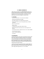
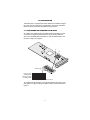
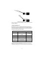
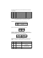
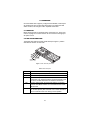
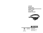
USER
MANUAL
MODEL 1052
iDSL Modem with
RS-232 Interface
Part# 07M1052-B
Doc# 058061UB
Revised 5/24/02
An ISO-9001
Certified
Company
SALES OFFICE
(301) 975-1000
TECHNICAL SUPPORT
(301) 975-1007
TABLE OF CONTENTS
1.0
1.1
1.2
1.3
Warranty Information .................................................................
FCC Information ...........................................................................
CE Notice......................................................................................
Service..........................................................................................
2.0
2.1
2.2
General Information.................................................................... 6
Features........................................................................................ 6
Description.................................................................................... 6
3.0
3.1
Configuration .............................................................................. 7
Configuring the Hardware DIP Switches ...................................... 7
Configuring DIP Switch S1 ........................................................... 8
Switches S1-1 and S1-2: Data Rate ...................................... 8
Switch S1-3 ........................................................................... 9
Switch S1-5: Asynchronous/Sync Operation ......................... 9
Switches S1-6 and S1-7: System Clock Mode ...................... 9
Switch S1-8 ......................................................................... 10
Configuring DIP switch S2.......................................................... 10
Switch S2-1: 19.2 kbps Synchronous Rate ......................... 10
Switch S2-2: Must be set to the ON position (Reserved). ... 11
Switches S2-3 ..................................................................... 11
Switches S2-4 and S2-5: Not Assigned .............................. 11
Switch S2-6 ......................................................................... 11
Switch S2-8: Not Assigned .................................................. 11
4.0
4.1
4.2
Installation.................................................................................
Connecting the Twisted Pair Interface........................................
Connecting the Connecting the Model 1052/A
(RS-232) .....................................................................................
Connecting the Model 1052/A (RS-232) to a DTE Device .........
Power Connection ......................................................................
Universal AC Power (100–240 VAC)..........................................
DC Power ...................................................................................
4.3
4
4
4
5
12
12
13
13
13
14
14
5.0
5.1
5.2
Operation................................................................................... 15
Power-up .................................................................................... 15
LED Status Monitors................................................................... 15
A
A.1
A.2
A.3
A.4
A.5
A.6
A.7
A.8
A.9
MODEL 1052 SPECIFICATIONS............................................... 16
Transmission Format ................................................................... 16
Transmission Line ....................................................................... 16
Control Signals ............................................................................ 16
Clocking ...................................................................................... 16
Distance ...................................................................................... 16
Data Rates .................................................................................. 16
LED Status Indicators ................................................................. 16
Connectors ................................................................................. 16
Power .......................................................................................... 16
2
A.10
A.11
A.12
A.13
A.14
Temperature Range .................................................................... 17
Altitude ........................................................................................ 17
Humidity ...................................................................................... 17
Weight ......................................................................................... 17
Line Interface .............................................................................. 17
B
Models 1052/A Factory Replacement
Parts and Accessories ............................................................. 18
C
Model 1052/A Interface Pin Assignments............................... 19
3
1.0 WARRANTY INFORMATION
Patton Electronics warrants all Model 1052 components to be free from
defects, and will—at our option—repair or replace the product should it
fail within one year from the first date of shipment.
This warranty is limited to defects in workmanship or materials, and does
not cover customer damage, abuse or unauthorized modification. If this
product fails or does not perform as warranted, your sole recourse shall
be repair or replacement as described above. Under no condition shall
Patton Electronics be liable for any damages incurred by the use of this
product. These damages include, but are not limited to, the following: lost
profits, lost savings and incidental or consequential damages arising
from the use of or inability to use this product. Patton Electronics specifically disclaims all other warranties, expressed or implied, and the
installation or use of this product shall be deemed an acceptance of
these terms by the user.
1.1 FCC INFORMATION
This equipment has been tested and found to comply with the limits for a
Class A digital device, pursuant to Part 15 of the FCC Rules. These limits
are designed to provide reasonable protection against harmful interference when the equipment is operated in a commercial environment. This
equipment generates, uses, and can radiate radio frequency energy and,
if not installed and used in accordance with the instruction manual, may
cause harmful interference to radio communications. Operation of this
equipment in a residential area is likely to cause harmful interference in
which case the user will be required to correct the interference at his own
expense. If this equipment does cause harmful interference to radio or
television reception, which can be determined by turning the equipment
off and on, the user is encouraged to try to correct the interference by
one or more of the following measures:
• Reorient or relocate the receiving antenna
• Increase the separation between the equipment and receiver
• Connect the equipment into an outlet on a circuit different from that to
which the receiver is connected
1.2 CE NOTICE
The CE symbol on your Patton Electronics equipment indicates that it is in
compliance with the Electromagnetic Compatibility (EMC) directive and
the Low Voltage Directive (LVD) of the Union European (EU). A Certificate
of Compliance is available by contacting Patton Technical Support.
4
Conformity documents of all Patton products can be
viewed online at www.patton.com under the appropriate
product page.
Important
1.3 SERVICE
All warranty and non-warranty repairs must be returned freight prepaid
and insured to Patton Electronics. All returns must have a Return Materials Authorization number on the outside of the shipping container. This
number may be obtained from Patton Electronics Technical Service at:
Tel: (301) 975-1007
E-mail: [email protected]
URL: www.patton.com
Note
Packages received without an RMA number will not be
accepted.
Patton Electronics’ technical staff is also available to answer any questions that might arise concerning the installation or use of your
Model 1052. Technical Service hours: 8AM to 5PM EST, Monday
through Friday.
5
2.0 GENERAL INFORMATION
Thank you for your purchase of this Patton Electronics product. This
product has been thoroughly inspected and tested and is warranted for
One Year parts and labor. If any questions or problems arise during
installation or use of this product, please do not hesitate to contact
Patton Electronics Technical Support at (301) 975-1007.
2.1 FEATURES
• Synchronous data rates: 19.2, 32, 56, 64, and 128 kbps
• Asynchronous data rates: 0–38.4 kbps
• Full duplex operation over a single twisted pair (2-wires)
• Point-to-point distances up to 5 miles (all data rates) on 24 AWG
twisted pair
• Multi-rate symmetric DSL
• RS232 Interface
• Compatible with popular Models 1092A and 1082
• Passes transmit and receive data, and one control signal in each
direction
• Universal power options, 120 VAC and -48, -24, and -12 VDC available
• Front panel status indicators
• Small, convenient desktop unit
• CE marked
2.2 DESCRIPTION
The Patton Model 1052 is a high speed, AC powered short range modem
that is able to operate synchronously or asynchronously—full duplex—
over a single twisted pair. Supporting data rates up to 128 kbps (synchronous) or 38.4 kbps (asynchronous), the Model 1052 is capable of
point-to-point distances up to 5 miles (8 km) using 24 AWG wire. The
Model 1052 supports internal, external or receive loopback clocking in
synchronous mode. Data rates and asynchronous data format may be
configured locally using DIP switches.
The Model 1052/A provides an RS232 interface on a DB-25 female connector. Line connection is made by an RJ-45 jack. Standard versions of
Model 1052 are powered by a 100–240 VAC (Universal) supply. The DC
power supply options support either -12, -24, or -48 VDC.
6
3.0 CONFIGURATION
The Model 1052 is equipped with 16 DIP switches that enable configuration of the unit for a wide variety of applications. This section describes
switch locations and explains the different config-urations
3.1 CONFIGURING THE HARDWARE DIP SWITCHES
S1 and S2 each contain eight internal DIP switches (see Figure 1) that
are used for configuration reset purposes only. To access switch set
SW1, use a small flat blade screwdriver to open the Model 1052’s case
as shown in Figure 2 on page 8.
S1
S2
N
O
1
2
3
O
4
N
5
S2
6
1
7
2
8
3
4
5
6
7
8
S1
ON
1
Switch toggle
Push toggle up
for ON position
Push toggle down
for OFF position
2
3
4
5
6
7
8
ON
1 2 3 4 5 6 7 8
Figure 1. DIP switches S1 and S2
To configure the DIP switches, use a small screwdriver and gently push
each switch to its proper setting. The ON and OFF positions are shown in
Figure 1.
7
Figure 2. Opening the Model 1052 case
Figure 1 on page 7 shows the orientation of the DIP switches in the “ON”
and “OFF” positions.
Configuring DIP Switch S1
DIP switch S1 is where you configure the data rate, asynchronous or
synchronous data format, transmit clock source. The following table summarizes default positions of DIP switches S1-1 through S1-8. Detailed
descriptions of each switch follow the table.
Position
S1 Summary Table
Function
S1-1
Data Rate
Off
S1-2
Data Rate
Off
S1-3
Reserved
On
S1-4
Reserved
On
S1-5
Async/Sync Data Format
Off
S1-6
Tx Clock Source
On
S1-7
Tx Clock Source
On
S1-8
Reserved
Off
Factory Default
}
128K Sync
}
Internal Clock
Switches S1-1 and S1-2: Data Rate. Use switches S1-1 and S1-2 to
configure the asynchronous or synchronous data rate of the Model 1052.
8
Each setting represents one synchronous data rate and one asynchronous data rate.
S1-1
S1-2
Sync Data Rate
Async. Data Rate
Off
On
Off
On
Off
Off
On
On
Off
Off
kbps or 19.2 kbps
32 kbps
56 kbps
64 kbps
128 kbps (see note)
Reserved
Reserved
Reserved
Reserved
0–38.4 kbps
Note
If the S2-1 switch is positioned in the OFF position, the 128 kbps
sync data rate/0–38.4 kbps async data rate option is selected.
Switch S1-3. Must be set to the On position (Reserved).
S1-3
Setting
On
Reserved
Switch S1-4: Must be set to the ON position (Reserved).
S1-4
Setting
On
Reserved
Switch S1-5: Asynchronous/Sync Operation. Use Switch S1-5 to
configure the Model 1052 for async/sync operation. Switch S1-5 must be
set in the Off position. There is no other valid setting.
S1-5
Setting
Off
Async/Sync
Switches S1-6 and S1-7: System Clock Mode. Use Switches S1-6
and S1-7 to configure the 1052 for internal, or receive recover clock
mode.
S1-6
S1-7
Clock Mode
Description
On
Off
On
On
Internal
External (DTE)
On
Off
Receive Recover
System clock generated internally
System clock derived from terminal interface
System clock derived from the
received line signal
Off
Off
Hardware Reset
9
A pair of Model 1052s communicate synchronously
across the twisted pair line connection. Therefore, you
must set these switches whether your application is
async or sync. For Sync or Async applications, please
configure one Model 1052 for internal clock mode and the
other Model 1052 for receive recover clock mode.
Important
Switch S1-8. Must be set to the Off position (Reserved).
S1-8
Setting
Off
Reserved
Configuring DIP switch S2
Use the eight DIP switches in S2 to enable 19.2 kbps synchronous operation and set the loopback modes. The following table summarizes
default positions of DIP switches S2-1 through S2-8. Detailed descriptions of each switch follow the table.
Table 1: S2 Summary Table
Position
Function
Factory Default
S2-1
S2-2
S2-3
S2-4
S2-5
S2-6
S2-7
S2-8
19.2 kbps Enable
RESERVED
Reserved
Not Assigned
Not Assigned
Reserved
Compatibility Mode
Not Assigned
Off
Off
Off
Off
Off
Off
Off
Off
Switch S2-1: 19.2 kbps Synchronous Rate. Enable Switch S2-1 to
allow the Model 1052 to operate at the 19.2 kbps synchronous data rate.
S2-1
Activation
Description
Off
Disabled
On
Enabled
Synchronous data rate is 32–128 kbps as
defined by switches S1-1 and S1-2
Model 1052 operates at synchronous 19.2 kbps
data rate
10
Switch S2-2: Must be set to the ON position (Reserved).
S2-2
S2-2 Setting
On
Reserved
Switches S2-3. Must be set to the Off position (Reserved).
S2-3
Description
Off
Reserved
Switches S2-4 and S2-5: Not Assigned.
Switch S2-6. Must be set to the Off position (Reserved).
S2-6
Description
Off
Reserved
Switch S2-8: Not Assigned.
11
4.0 INSTALLATION
Once the Model 1052 has been configured, it is ready to connect to the
twisted pair interface, to the serial port, and to the power source. This
section tells you how to make these connections.
RS-232
port
ER
LL
D
D
ith
W ce
el rfa
od te
M In
L 2
S 3
iD S-2
R
NS
DS
RX
TX
IN
K
del
Mo
2/A
105
d
lan
ary
,M
rsb
urg
ith
e
Ga
RJ-45 DSL
interface
Power jack
Figure 3. Model 1052 Rear Panel
4.1 CONNECTING THE TWISTED PAIR INTERFACE
The Model 1052 supports communication between two DTE devices at
distances to 5 miles (8 km) over 24 AWG (0.5mm) twisted pair wire. Two
things are essential:
• These units work in pairs. Both units at the end of the twisted pair DSL
span must be set for the same DTE rate.
• To function properly, the Model 1052 needs one twisted pair of metallic
wire. This twisted pair must be unconditioned, dry, metallic wire,
between 19 (0.9mm) and 26 AWG (0.4mm) (the higher number
gauges will limit distance). Standard dial-up telephone circuits, or
leased circuits that run through signal equalization equipment, or standard, flat modular telephone type cable, are not acceptable. The RJ-45
connector on the Model 1052’s twisted pair interface is polarity insensi-
12
tive and is wired for a two-wire interface. The signal/pin relationships
are shown in Figure 4.
Figure 4. Model 1052 twisted pair line interface
4.2 CONNECTING THE CONNECTING THE MODEL 1052/A
(RS-232)
The Model 1052/A supports RS-232 serial port connections. This section
describes how to connect the serial ports to your RS-232 equipment.
Connecting the Model 1052/A (RS-232) to a DTE Device
The Model 1052/A provides an RS-232 DCE (data communications
equipment) interface on a DB-25 female connector. As a DCE, this interface is designed to connect to DTE equipment, such as a router. When
connecting the RS-232 interface of the Model 1052/A to your DTE
device, use an RS-232 straight-through cable (see Figure 5). Appendix C
on page 19 describes pin assignments and signal sources for the Model
1052/A RS-232 interface. When purchasing or constructing an interface
cable, use the pin diagrams in Appendix C as a guide.
Model 1052
Gaithersburg, Maryland
Model 1052/A
DSL Span
TM
ER
NS
TXD
RXD
DSL LINK
iDSL Modem With
RS-232 Interface
TXD
RXD
DSL LINK
NS
ER
TM
Straight-through 25-pin
D-sub cable
iDSL Modem With
RS-232 Interface
Model 1052/A
Gaithersburg, Maryland
Model 1052 (DCE)
V.24 Router (DTE)
Figure 5. Connecting the Model 1052/A to an RS-232 serial DTE
4.3 POWER CONNECTION
The Model 1052 (all versions) are available with Universal AC (100–240
VAC), 120 VAC, 230 VAC or -12, -24, or -48 VDC power options. This
section describes these options.
13
Universal AC Power (100–240 VAC)
The Model 1052 uses a 5VDC, 2A universal input 100-240VAC, power
supply (center pin is +5V). The universal input power supply has a male
IEC-320 power entry connector. This power supply connects to the
Model 1052 by means of a barrel jack on the rear panel. Many international power cords are available for the universal power supply (Refer to
Appendix B on page 18 for country-specific power cords. The Model
1052 powers up as soon as it is plugged into an AC outlet—there is no
power switch.The Universal AC supply is equipped with a male IEC-320.
DC Power
The optional -12, -24, or -48 VDC DC-to-DC adapter supplied with the
DC version of the Model 1052 plugs in a DC source (nominal -12, -24, or
-48 VDC) and plugs into the barrel power supply jack on the rear of the
1052. Refer to Figure 6 to make the proper connection.
To Power
Supply Jack
-Vin
To -48VDC
Source
+Vin
Figure 6. Connecting DC power to the 48V-PSM DC power supply
WARNING
There are no user-serviceable parts in the power supply
section of the Model 1052. Fuse replacement should only
be performed by qualified service personnel. Contact
Patton Electronics Technical support at
+1 (301) 975-1007,
via our web site at www.patton.com, or by E-mail at
[email protected], for more information.
14
5.0 OPERATION
Once the Model 1052 is properly configured and installed, it should operate transparently. This sections describes power-up, reading the LED
status monitors, and using the built-in loopback test modes.
5.1 POWER-UP
Before applying power to the Model 1052, read section 4.3, “Power Connection” on page 13 to ensure that the unit is connected to the appropriate power source.
5.2 LED STATUS MONITORS
The Model 1052 features five side panel LEDs (see Figure 7). Table 2
describes the function of each LED.
Figure 7. Model 1052 side panel LEDs
Table 2: LED descriptions
LED
Description
TXD
RXD
DSL LINK
(Active: Green) When lit, indicates data transmission.
(Active: Green) When lit, indicates data transmission.
(Active: Green) When lit, indicates that the end-to-end DSL
framer link is up, signifying that the link across the DSL span
is active. The DSL Link LED is off when the link is down.
(Active: Yellow) When the No Signal LED is lit, it indicates
that the local Model 1052 is not connected with the remote
Model 1052
(Active: Red) Flashing red indicates that there are CRC errors
on the DSL (framer) side if the DSL Link is active. ER flashes
once to indicate a CRC error during normal operation
NS
ER
15
APPENDIX A
MODEL 1052 SPECIFICATIONS
A.1 TRANSMISSION FORMAT
Synchronous or asynchronous
A.2 TRANSMISSION LINE
Single unconditioned twisted pair
A.3 CONTROL SIGNALS
CD and RTS
A.4 CLOCKING
Internal, external, or receive loopback
A.5 DISTANCE
Distance, max, all data rates:
• 10.1 miles (16.4km) on 19 AWG (0.9mm) wire
• 7.2 miles (11.5 km) on 22 AWG (0.64mm) wire
• 5.0 (8 km) on 24 AWG (0.5mm) wire
• 3.4 (5.5 km) on 26 AWG (0.4mm) wire
A.6 DATA RATES
• Synchronous: 19.2, 32, 56, 64, and 128 kbps
• Asynchronous: 0–38.4 kbps
A.7 LED STATUS INDICATORS
TXD, RXD, DSL Link, NS (no signal), ER (CRC error)
A.8 CONNECTORS
RJ-45 on DSL line side; DB-25 female on serial interface side
A.9 POWER
100–253 VAC, 50–60 Hz (universal input option); 48 VDC (optional),
5 watts
16
A.10 TEMPERATURE RANGE
32–122°F (0–50°C)
A.11 ALTITUDE
0–15,000 feet (0–4,572 meters)
A.12 HUMIDITY
5–95% non-condensing
A.13 WEIGHT
2.01 lbs. (1.0 kg)
A.14 LINE INTERFACE
Transformer coupled 1500 VAC isolation
17
APPENDIX B
MODELS 1052/A FACTORY REPLACEMENT
PARTS AND ACCESSORIES
Model #
Description
1052/A
12V-PSM
24V-PSM
48V-PSM
08055DCUI
0805EUR
0805UK
0805US
0805AUS
0805DEN
0805FR
0805IN
0805IS
0805JAP
0805SW
07M1052
RS232 iDSL Modem
12 VDC Power Supply Module
24 VDC Power Supply Module
48 VDC Power Supply Module
100-240VAC (+5V ±5% reg. DC/2A) Universal Input Adapter
European Power Cord CEE 7 (“A”)
United Kingdom Power Cord (“D”)
American Power Cord (“K”)
Australia/New Zealand Power Cord (“C”)
Denmark Power Cord (“E”)
France/Belgium Power Cord (“F”)
India Power Cord (“G”)
Israel Power Cord (“H”)
Japan Power Cord (“J”)
Switzerland Power Cord (“L”)
User Manual
18
APPENDIX C
MODEL 1052/A INTERFACE PIN ASSIGNMENTS
RS-232 INTERFACE
(DB-25 Female Connector)
(DCE Orientation)
Pin #
Signal
1
2
3
4
5
6
7
8
15
17
18
20
21
24
25
Shield GND
TD (Transmit Data) (DTE Source)
RD (Receive Data) (DCE Source)
RTS (Request to Send) (DTE Source)
CTS (Clear to Send) (DCE Source)
DSR (Data Set Ready) (DCE Source)
SGND (Signal Ground)
CD (Carrier Detect) (DCE Source)
TC (Transmitter Clock) (DCE Source)
RC(Receiver Clock) (DCE Source)
LL (Local Analog Loopback)
DTR (Data Terminal Ready) (DTE Source)
RDL (Remote Digital Loopback)
XTC (External Transmit Clock) (DTE Source)
TM (TM (Test Mode) (DCE Source)
19
Notes
_________________________________________________________
_________________________________________________________
_________________________________________________________
_________________________________________________________
_________________________________________________________
_________________________________________________________
_________________________________________________________
_________________________________________________________
_________________________________________________________
_________________________________________________________
_________________________________________________________
_________________________________________________________
_________________________________________________________
_________________________________________________________
_________________________________________________________
_________________________________________________________
_________________________________________________________
_________________________________________________________
_________________________________________________________
_________________________________________________________
_________________________________________________________
Copyright © 2002
Patton Electronics Company
All Rights Reserved.
20